Coagulation Using Kerosene for Magnetic Deinking of Waste Office Paper
*
1Tatsuya Oki
1, Shuji Owada
2, Hiroki Yotsumoto
1, Hirokazu Tanuma
3;*2and Yuu Takeuchi
3;*31Particle Separation Group, Research Institute of Green Technology, National Institute of Advanced Industrial Science and Technology,
Tsukuba 305-8569, Japan
2
Department of Resources and Environmental Engineering, Science and Engineering, Waseda University, Tokyo 169-8555, Japan
3Mineral Resources Engineering Specialization, Major in Mineral Resources Engineering and Materials Science and Engineering,
Graduate School of Waseda University, Tokyo 169-8555, Japan
A method for disintegrating waste office paper using kerosene was reported in our previous paper, which achieved almost a 100% liberation of toner from paper fibers. The liberated toner must be completely separated to realize effective deinking. Recently, a new method for deinking waste officer paper by magnetic separation after hetero-coagulation of magnetic and non-magnetic toner by 1-octadecanol was reported by Augustaet al.Under this method, coagulation was carried out at 72C. The 1-octadecanol liquid was then cooled to produce strong solid
coagulates. As reported in our previous paper, kerosene has the ability to soften toner, and strong coagulates for magnetic separation may be produced by their adhesion when used as a flocculant. The present study investigated the size of toner particles liberated by the kerosene disintegration method, and compared the bonding strength between the toner particles coagulated by the addition of kerosene as a flocculant to those coagulated with 1-octadecanol. After these investigations, the coagulating and deinking properties of kerosene and 1-octadecanol were compared by rejecting toner coagulates with a neodymium-boron magnet. The results showed that nearly perfect deinking can be achieved with little paper loss, even in ambient temperature, due to the large and strong coagulates produced by this method. When kerosene was used in the disintegration and coagulation stages, the average coagulate size was 1114mm, and a deinking percentage of 98.4% was attained through separation with a neodymium-boron magnet.
(Received June 21, 2002; Accepted November 8, 2002)
Keywords: paper recycling, office paper, deinking, toner, kerosene, coagulation, magnetic separation
1. Introduction
The amount of waste office paper produced by photo-copying machines and laser printers is gradually increasing.1) Most waste office paper is assumed to be regenerated as high-grade paper because of its high quality and whiteness. However, the rate of waste office paper regeneration has not increased.1) One of the sources of this problem is the difficulty of liberating toner from paper fibers; another is the difficulty of removing the toner so that no specks remain on the paper. The former problem exists because, unlike with conventional oil-based ink, toner cannot be saponificated in alkali solution. In conventional studies, toner liberation has been promoted by various methods of comminuting waste office paper into fine particles. However, these are not ideal separation methods because paper fibers also get cut in the processes.2) A disintegration method for waste office paper using kerosene was investigated in our previous paper.2)We reported a toner liberation of almost 100% without cutting the paper fibers, even under weak stirring conditions, by soaking the paper in alkali and kerosene before disintegra-tion. However, toner specks, which are a source of trouble in the separation stage, are visible black spots more than 30mm remain on regenerated paper. Their existence hampers the distribution of high-grade regenerated paper, such as office paper.
It is within these parameters that separation methods to decrease toner specks have been reported, most utilizing flotation.3)From the context that complete removal of toner
specks is impossible by flotation, methods such as positively changing the properties of toner particles rather hydrophilic than hydrophobic, have been investigated actively in the waste paper industry.4–7) Although this method may not increase the deinking percentage, it could potentially sup-press the creation of toner specks. Toner would thus remain on regenerated paper as fine particles, since toner coagulation could be checked in the flotation cell. However, this system of recycling waste office paper has not yet been implemented because toner specks cannot be completely removed by flotation, even under various conditions.
Recently, a new deinking method by magnetic separation has been examined.8–10) It was anticipated that magnetic separation would decrease the incidence of toner specks because it easily separates particles over several hundred micrometers in size. Such particles are not removed easily by flotation. There are two classifications of toner; magnetic, which contains magnetic powder, and non-magnetic, which does not contain any magnetic powder. Gubitz et al.8) reported a 92.7% deinking percentage for magnetic toner when magnetic separation was conducted after enzymatic treatment. Furthermore, Augusta et al.9,10) reported a magnetic separation method for waste office paper containing both magnetic and non-magnetic toner by coagulating both toners together. The selection of a flocculant that produces large and strong coagulates is especially important for this method. If the coagulation bonding strength is weak, coagulates will break, and only magnetic toner would be recovered. Moreover, small-diameter coagulates would be carried away by the flow of fluid and not be recovered by a magnet if their content of magnetic toner was low.9) So by using 1-octadecanol, whose melting point is 60C, as a flocculant, Augusta et al.produced coagulates at 72C and cooled it down to ambient temperature to solidify the
*1This Paper was Originally Published in Japanese in Journal of the Mining
and Materials Processing Institute of Japan118, No. 3, 4 (2002). *2Graduate Student, Waseda University. Present address: Keihin
Corpora-tion, Kakuda 981-1581, Japan. *3Graduate Student, Waseda University.
flocculants. Strong coagulates averaging 120.5mm in size were produced by this method and separated by a magnetic separator with a magnetic flux density of 0.3 T. The results showed that only 7% of paper fiber was lost and that a deinking percentage of 90.8% was attained. However, this process, which lowers the liquid to ambient temperature right after raising it to 72C requires further examination in terms of energy consumption.
A method to soften toner with kerosene was investigated in our previous paper,2)which resulted in a high degree of toner liberation by weak stirring. As the adhesion of toner increases slightly by kerosene soaking, there is a possibility that strong coagulates could be produced even at ambient temperature. This paper examines the bonding strength of toner softened by kerosene and the application of kerosene as a flocculant for the coagulation and magnetic deinking method.
2. Experimental
2.1 Sample
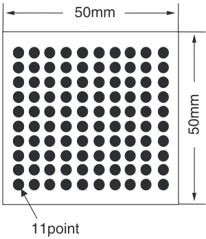
Toner is classified by whether or not it contains magnetic powder and by the kinds of resin from which it is composed. Magnetic toner made of styrene-acrylic resin (Canon: CRG-EPKS II, resin content: about 40%), and non-magnetic toner made of multiple resin containing polyester resin (Fuji-Xerox: D282, resin content: about 90%), were used as toner samples in this study, as in our previous paper.2) The magnetic toner’s magnetic powder content was estimated to be 58% from the quantitative results of an ICP analysis of iron. The size distributions of both toner samples were measured by a continuous flow image analyzer (Nireco: Luzex SE-SPL). The 50% diameter by volume of both samples was 8.7mmfor the magnetic and 15.3mm for the non-magnetic toner, respectively. The model waste paper samples were prepared by printing 100 black circles (11 point font) on one side of A4 photocopy paper (NBC-Ricoh:90-2218, 65 g/m2) with a laser printer (Canon: Laser Shot
B406E) using magnetic toner samples at first. Next, a copy of this printed paper was made on the same type of A4 paper with a photocopying machine (Fuji-Xerox: Vivace 720) using non-magnetic toner. Then, these two pieces of printed paper were cut into50 mm50 mmpieces (Fig.1) weighing 0.15 g and used as model waste paper for experimentation.
2.2 Experimental methods
2.2.1 Disintegration of model waste paper sample
Disintegration of a model waste paper sample was conducted by the kerosene disintegration method based on the results of our previous paper.2)A model sample (0.15 g) was washed with de-ionized water after being soaked in 100 mL of 8% sodium hydroxide solution for 12 h. This sample was then put into a 1% kerosene emulsion, which had been emulsified with a disperser (Yamato: LK-21) at 333.3 s 1 for 1 min and soaked for 30 min, while being
stirred at 2 s 1 by a stainless impeller (rotation diameter: 50 mm). Although the paper kept its prototype without disintegrating and the toner peeling off, the toner softened and the wedged particles infiltrating the paper fibers became easier to remove. After washing in 100 mL of 8% sodium hydroxide solution and stirring by impeller at 8.3 s 1 for 5 min, a disintegrated sample was obtained with the toner liberated. The 0.15% pulp concentration of was used in all experiments.
2.2.2 Measurement of printed toner thickness
The appearance of printed toner and toner liberated by the kerosene disintegration method was observed through a microscope. The model waste paper samples were used to observe printed toner; liberated toner was observed on a glass plate (18 mm24 mm). The thicknesses of the toner on copy paper and overhead projector transparency (Gakushu-ken-kyusha, No. 87241), each respectfully printed with a laser printer and a photocopying machine (i.e., four different samples), were measured with a digital micrometer (Mitsu-toyo: MDC-25M; diameter of measurement area:6.34 mm). The values were calculated from the difference between the printed and non-printed parts. The border between the unprinted paper and toner was observed by SEM, and the difference in height between them was measured by AFM (JEOL: JSPM-4200) to confirm the characteristics of the printed model waste paper sample. Measurements by AFM were carried out in contact mode (measurement area:
60mm60mm).
2.2.3 Measurement of size distribution of toner
Toner particle size was measured after a model waste paper sample printed with magnetic toner was disintegrated so that it could be easily recovered by a magnet. The disintegrated suspension was put into a 300 mL beaker and stirred slowly so that the sample would disperse. Toner was then recovered with a 30 mm (0.45 T) neodymium-boron magnet. The recovered toner was placed on a microscope and its image was fed into a personal computer through a video camera in order to measure the area of each toner particle by image analysis software (Mitani: Winroof). Although the Heywood diameter calculated from this area was shown as the toner size based on the area in our previous paper,2)this would have lead to large errors when toner from disintegrated samples is compared to toner before being printed because the shape of the former is flat and the latter is irregular. So, sphere-equivalent volume was calculated from the Heywood diameter for toner before being printed. In the case of toner from the disintegrated samples, the area calculated by image analysis was converted to volume by multiplying the area by the toner thickness obtained in 2.2.2. The sphere-equivalent diameter was then calculated based on this volume. All size
50mm
50mm
11point
[image:2.595.93.243.595.769.2]distributions in this study are shown based on volume.
2.2.4 Measurement of toner bonding strength
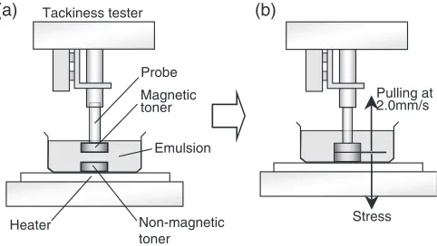
Pulling stress was measured by a tackiness tester (Malcom: TK-1) after magnetic and non-magnetic toner contacted each other, which corresponds to the bonding strength between the two kinds of toner. Measurements were carried out following method JIS Z3284, which outlines an adhesion measurement for solder paste. To make a 3 mm tablet sample, 0.3 g of magnetic and non-magnetic toner samples before being printed were pressed by a hydraulic press at 20 MPa for 5 min using a 10 mm tablet cell. The surfaces of both tablet samples were glossy and smooth, even without being polished. A sample tablet of magnetic toner was glued to the tip of the tackiness tester’s stainless probe (column shape:
5.1 mm) and that of non-magnetic toner was glued to the bottom of a 25 mL weighting bottle, which was set to a tackiness tester. The weighting bottle was then filled with either 10 mL of kerosene emulsion or 1-octadecanol emul-sion of several concentrations so that the contact side of both samples would soak as shown in Fig. 2(a). Following the examinations of Augusta et al.,9) in the case of using 1-octadecanol, the tablet samples were soaked for 30 min in emulsions, which were kept at 70C by a heater. To stir the emulsion, a small amount (310 6m3/s) of air was blown
obliquely down onto the surface of the emulsion tangentially from the weighing bottle because mechanical stirring was difficult for this experiment. Both samples were put under a force of 0.157–0.549 N for 1 min immediately after being soaked. While under pressure, the emulsion was rapidly cooled down to 20C by spraying a coolant around the weighing bottle to solidify the 1-octadecanol, and the pulling stress at 2.0 mm/s pulling speed was measured (Fig. 2(b)). For the measurements in kerosene, pressing time, pressing force, and pulling velocity were the same as for 1-octadecano; temperature, however, was fixed at 20C.
2.2.5 Coagulation and magnetic deinking of
disintegra-ted sample
After disintegrating each model waste paper sample of magnetic and non-magnetic toner (total: 0.3 g) by the method outlined in 2.2.1, they were coagulated to each other by stirring in a 200 mL beaker the disintegrated samples into 100 mL of kerosene or 1-octadecanol emulsion. Concentra-tions of the emulsions were 0.02%, 1%, and 50% for kerosene and 0.02% for 1-octadecanol. Taking into account
the coagulation properties during stirring, 50% kerosene was used here instead of non-diluted kerosene. Although the details of coagulation conditions were not identified in Augustaet al.’s paper,9)the impeller revolution and stirring time was assumed to be 3 s 1 and 15–45 min, respectively,
based on the study by Synder et al.13) So, coagulation experiments were carried out in the present study at 3 s 1for
45 min by the same impeller used in 2.2.1. After stirring, coagulate sizes were calculated by converting their Heywood diameters, which had been measured by image analysis (to 2.2.3), to sphere-equivalent volume.
Separation was carried out by the neodymium-boron magnet used in 2.2.3. This magnet contacted all coagulates in the suspension —without putting any of its weight on them— through a 150mmthick glass film after coagulation. Then, the magnet together with the glass plate was picked up and coagulates attracted by the magnet over the glass were recovered by washing them off with water. The same kind of magnetic separation was carried out once more on these recovered coagulates. Coagulates that were twice recovered by magnet were grouped as a magnetic product; all of the others were grouped as a non-magnetic product. Sphere-equivalent volumes of the magnetic and a non-magnetic products were obtained by the same method as mentioned above, and the deinking percentage by volume was calcu-lated.
3. Results and Discussion
3.1 Shapes and sizes of toner after kerosene
disintegra-tion
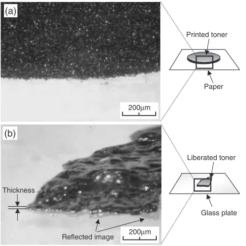
Making large coagulates is necessary to recover as much toner as possible by magnet in the coagulation and magnetic deinking process.9) Knowing the feed size is important to evaluate the sizes of coagulates made under various coagulation conditions. To know the exact size of a toner particle, it is necessary to measure its area and thickness because toner liberated by kerosene forms a flat shape.2,11,12) Although area could be measured by image analysis, measuring thickness is more difficult. Figure 3 shows microscopic images of printed toner (a) and toner liberated by the kerosene disintegration method (b), from the point of view of the thickness of the paper. Each image is actually made up of a combination of five separate images, each one focusing on a point at a particular depth in the original image. These figures are for non-magnetic toner, whose appearance differs from that of magnetic toner only slightly. Since the surface of printed toner appears gritty because of coagulated particles, the thickness cannot be estimated. On the other hand, liberated toner has a glossy and billowy smooth surface. Kerosene soaking is considered to change the toner into a softened state. The thickness of the non-magnetic toner was estimated to be about 10mm(the thickness in Fig.3(b)) from the shape of the end. The thickness of the magnetic toner seemed to be slightly thinner than that of the non-magnetic toner. In this way, it would be difficult to measure the thickness of liberated toner directly by a micrometer or probe-microscope because it has a wavy surface and the bottom is not glued onto the glass plate, as has been found by reflected images. So, the thickness of the printed toner was Probe
Magnetic toner
Emulsion
Non-magnetic toner Heater
Tackiness tester
Pulling at 2.0mm/s
Stress
(a) (b)
[image:3.595.49.290.621.757.2]investigated in detail and compared to that of a microscopic image (Fig.3(b)).
To calculate the actual thickness of the toner, the thickness at the printed part and non-printed area of paper or transparency that had been printed by either magnetic or non-magnetic toner were first measured by a digital micro-meter. The differences were calculated as the thickness of printed toner. The results are shown in Table1. The average value of measurements taken at 30 different points is shown. In the case of printing to paper, the difference in thickness between printed and non-printed parts was 3.9mm for magnetic toner and 6.3mm for non-magnetic toner. When printed on a transparency, the difference was 4.6mm for magnetic toner and 8.1mmfor non-magnetic toner. Printed toner on paper was classified into the upper part on paper and the wedged part that infiltrated the paper fiber as shown in Fig.4. As toner does not infiltrate a transparency, the thickness is considered to be the sum of both parts; i.e., the total thickness of printed toner. The difference between the
toner thickness on paper and transparency was estimated to be the thickness of the wedged part that infiltrated the paper fiber. That thickness was 0.7mm for magnetic toner and 1.8mmfor non-magnetic toner. The thickness of printed toner (magnetic: 4.6mm, non-magnetic: 8.1mm) approximated that of the liberated toner observed in Fig.3(b).
On the other hand, these printed toner thicknesses are so thin that they do not even reach particle size at 50 vol% of toner before being printed (magnetic toner: 8.7mm, non-magnetic toner: 15.3mm). So, the borderline of printed and non-printed areas of a model waste paper sample was observed by SEM to confirm the state of printed toner. Figure 5 shows an SEM image of magnetic toner on a sample. Although some toner about 10mm in diameter can be observed on the printed area, much of the toner has been flattened by the heat from printing. Figure6shows an AFM image of the border. The depth profiles show that the difference between the upper part on paper and the toner surface is about 4mm, which corresponds with the measure-ments taken by a digital micrometer (3.9mm). Therefore, the measurements by micrometer seem to indicate the exact
200µm 200µm
Printed toner
Paper
Liberated toner
Glass plate Thickness
Reflected image (a)
(b)
[image:4.595.47.295.72.320.2]Fig. 3 Microscopic images of printed and liberated non-magnetic toner (viewed from thickness direction). (a) printed toner (model waste paper sample). (b) liberated toner (liberated by kerosene disintegration method).
Table 1 Thickness of printed toner.
Measuring
On paper On transparency
parts
Difference Difference
Thickness of thickness Thickness of thickness D/mm D/mm D/mm D/mm
Non-printed 89.5 — 104.4 —
(s = 1.9) (s = 1.3)
Printed with 93.4
3.9 109.0 4.6
magnetic toner (s = 2.0) (s = 0.9)
Printed with 95.8
6.3 112.5 8.1
non-magnetic toner (s = 1.7) (s = 0.8)
Difference of thickness between printed and non-printed parts.
s: Standard deviation.
Toner
Upper part
Wedge part
Paper fiber
Fig. 4 Illustration of printed toner.
Printed toner
Paper fiber
10µm [image:4.595.299.546.80.251.2] [image:4.595.308.547.306.487.2] [image:4.595.47.290.394.523.2]thickness of toner in its printed state. From the results, it has been shown that the thickness of toner liberated by kerosene and that of printed toner is almost the same, although they appear different. In what follows, the value of 4.6mm, which was measured in 3.1, will be regarded as the thickness of magnetic toner resulting from disintegration treatments.
Next, using a model sample printed with magnetic toner, the areas of printed toner (black circles) and toner after being disintegrated using 1% kerosene emulsion and undiluted kerosene were measured and then converted to volume by multiplying it by the toner thickness obtained in 2.2. This value for volume was then used to calculate the sphere-equivalent diameter. The Heywood diameter was directly used as sphere-equivalent diameter for a magnetic toner sample before being printed. Toner size distribution by volume is shown in Fig. 7. Particle size at 50 vol% of toner before being printed (Fig.7: original) was 8.7mm as mentioned in 2.1, and the maximum diameter was 13.5mm. The sphere-equivalent diameter of the black circles was calculated to be 396mm from their volume, which was calculated by multiplying the area of black circles to the thickness of the printed toner. The particle sizes at 50 vol% for toner samples disintegrated in undiluted kerosene and 1% kerosene emulsion were 280mm and 304mm respectively, which was almost the same as those for printed toner. The incidence of particles below 100mmwas very low: 3.0% in undiluted kerosene and 0.4% in 1% kerosene, which indicates that most particles maintained the bond that was established when being printed and did not comminute into fine particles. It was assumed that particles disintegrated in
undiluted kerosene were smaller than those done in 1% kerosene because the toner had already detached from the paper during the process of disintegration in sodium hydro-xide solution, which led to little progress in the grinding by stirring.
3.2 Bonding strength of coagulated toner by kerosene
flocculant
Augustaet al.9)also investigated the use of kerosene or n-heptane as a flocculant and reported them to be unsuitable for this deinking method because the bond between toner particles was insufficient to keep them from breaking. In their study, flocculant had been added at a rate of 2% of paper into 1% pulp;i.e., the flocculant concentration in water had been 0.02%. From our previous results,2)it is considered that toner cannot be softened at this kerosene concentration and would not yet show adhesive properties. So, bonding strengths of toner were examined for cases when kerosene was used as flocculants at concentrations of 0.02%, 1%, and without dilution. Also, the bonding strength was measured between magnetic and nonmagnetic sample tablets that were put into 1-octadecanol and had been cooled down in order to solidify after being heated to 70C. The relationship between pressure and pulling stress (bonding strength) of magnetic and non-magnetic sample tablets is shown in Fig.8. Each plot shows the average of five measurements. The results for samples soaked in kerosene were reproducible and the relationship between pressure and pulling stress was quite linear. Pulling stress increased with kerosene concentration: 10.4–15.5 kPa and 20.4–36.4 kPa for 1% kerosene and undiluted kerosene, respectively, while it was 2.9–3.9 kPa for 0.02% kerosene. These results indicate that toner is softened only slightly with 0.02% kerosene, but adhesion increases kerosene concentrations over 1%. Conversely, the results of soaking in 1-octadecanol are more scattered than the results for those in kerosene. It is regarded that the variation in adhesion in each measurement, which was larger than that of kerosene, influenced the results because octadecanol shows high stress, even with small amounts of 1-octadecanol, compared to kerosene. The five results of each plot varied between 15–35 kPa, so the average was about 25 kPa for each level of pressure. Since toner size and stirring conditions were different from the real process, and because
Fig. 6 AFM image and profile for depth direction around the border of paper and magnetic toner on a model waste paper sample.
0 10 20 30 40 50 60 70 80 90 100
1 10 100 1000
Particle Diameter,D
Cum
ulativ
e V
o
lume
P
e
rcentage
Disintegrated by 1% kerosene
Disintegrated by undiluted kerosene
Printed Original
/µm
[image:5.595.49.287.68.379.2] [image:5.595.317.537.73.223.2]the values depend on the smoothness of the toner surface, these absolute values could vary depending on conditions. However, relatively speaking, the pulling stress of 1-octadecanol was 10 times higher than that of kerosene at the same concentration, which substantiates Augustaet al.’s description9)of bonding strength. Using kerosene at concen-trations over 1%, the pulling stress was high, even at ambient temperature, because of its adhesion. In the case of 1% kerosene, the bonding strength was about half that of 1-octadecanol, and in undiluted kerosene it was equal to or more than 1-octadecanol.
3.3 Coagulation properties
Model samples using magnetic and non-magnetic toner were disintegrated by the kerosene disintegration method and coagulated by stirring the mixtures after the addition of kerosene or 1-octadecanol as a flocculant. The size at 50 vol% of coagulated toner is shown in Fig.9. Particle size at 50 vol% of magnetic toner before being coagulated was 304mm, as shown in 3.2. On the other hand, the particle size at 50 vol% of the coagulate made with 0.02% 1-octadecanol was 503mm, which is about 4.5 times in volume ratio. Using
kerosene of the same concentration as 1-octadecanol, the size at 50 vol% was 397mm(2.2 times in the volume ratio) and both the size of coagulates as well as bonding strength with kerosene was smaller than that with 1-octadecanol. However, the size of coagulates increased with higher concentrations. The size at 1% kerosene was 602mm(7.8 times in volume ratio); at 50% kerosene it was 1,114mm (49.2 times in volume ratio), which means that the particle size at 50 vol% can exceed 1 mm.
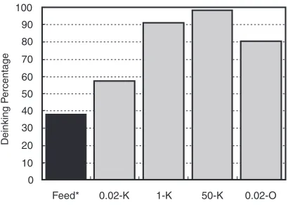
Next, coagulation properties of each coagulation reagent were investigated by separating magnetic and non-magnetic products with a neodymium-boron magnet. Figure10shows the deinking percentage (volume percent) by magnetic separation. The volume ratio of magnetic toner to total toner, which was calculated by the printed area of a model sample obtained in the previous paper2)and the thickness of printed toner obtained in 3.1, is also shown in this figure. The volume ratio of magnetic toner to total toner, which can be calculated by the difference in toner densities (magnetic: 1.70 g/cm3;
non-magnetic: 1.05 g/cm3) because these were mixed at1 : 1
by weight, was 38.2%. Therefore, it is suggested that coagulation occurred with every flocculant since deinking percentages were higher than 38.2%. Coagulation proceeds with the increase in kerosene concentration, which in turn leads to an increase in the deinking percentage. The deinking percentage was only 57.2% with 0.02% kerosene, but reached 90.9% with 1% kerosene and 98.4% with 50% kerosene. Although the deinking percentage of 80.4% with 1-octadecanol was higher than that with kerosene of the same concentration, it was obviously lower than the deinking percentage when using kerosene over 1%. The order of the deinking percentage corresponds with the size order of coagulates, which reveals that larger amounts of non-magnetic toner could be recovered by a magnet if larger coagulates were produced.
According to the theoretical calculations of Augusta et al.,9) when the magnetic powder content in the coagulates was 6%, the coagulates would have to have been about 1 mm in size in order to be recovered through resistance against inertia, even by using a 2 T magnetic separator (flow velocity: 0.1 m/s). Also, the coagulates would need to be about 500mm 0
10 20 30 40 50
1.0 1.5 2.0 2.5 3.0 3.5 4.0 4.5
Pressure, PP/ kPa
Pulling Stress
,
P
S
/kP
a
undiluted kerosene 1% kerosene 0.02% kerosene 0.02% 1-octadecanol
Fig. 8 Relation between pressure and pulling stress of magnetic and non-magnetic toner samples.
0 200 400 600 800 1000 1200
Feed* 0.02-K 1-K 50-K 0.02-O
P
a
rticle Diameter at 50V
ol%,
D
/µ
m
Fig. 9 Particle size of coagulated toner under several coagulating condi-tions. Feed: Disintegrated sample prepared by kerosene disintegration of
a printed sample using magnetic toner with 1% of kerosene. 0.02-K: 0.02% kerosene. 1-K: 1% kerosene. 50-K: 50% kerosene. 0.02-O: 0.02% 1-octadecanol.
0 10 20 30 40 50 60 70 80 90 100
Feed* 0.02-K 1-K 50-K 0.02-O
Deinking P
[image:6.595.59.280.71.240.2]ercentage
Fig. 10 Deinking rate by magnetic separation under several coagulating conditions. Feed: volume% of magnetic toner of feed. 0.02-K: 0.02%
[image:6.595.67.274.588.728.2] [image:6.595.325.530.594.740.2]in size at a magnetic powder content of 30% according to the relationships they illustrated. Since the ratio of magnetic powder to magnetic toner was 58% in the present study (see section 2.1), the ratio of magnetic powder to total toner by weight was about 29% in this experiment. Therefore, Fig.9 suggests that the coagulates produced by all conditions except 0.02% kerosene satisfied their theoretical required sizes and could potentially achieve almost a 100% deinking percentage using a 2 T magnetic separator. Also, in the case of using kerosene at concentrations over 1%, high deinking percentages are expected to be achieved even by a magnetic separator with a magnetic flux density lower than 2 T. Although these results were obtained with a model sample printed with a black circle on, the probability of producing very fine particles is low, even for real waste paper, because toner is liberated in a range of sizes close to printed toner by this disintegration method. The sphere-equivalent diameter is about 70–100mm, even when they are broken down width-and breadth-wise into 200–300mmsizes, which is considered to be the most highly grinded case for a character printed in 11 point font whose width is 200–300mm. When figures and pictures are printed, liberation as larger particles is expected. Only a small amount of paper fiber was observed by microscope in the recovered samples. Although the exact amount could not be measured, the loss of paper is estimated to be less than 1%. These results are led by advanced liberation of toner by the kerosene disintegration method, and it is suggested that advanced deinking could be achieved with a high level of paper recovery if paper straying into toner at the magnetic separator could be controlled.
It has been confirmed that coagulation of magnetic and non-magnetic toner is promoted by using over 1% kerosene as a flocculant, and that this improves deinking. Large and strong coagulates are formed at ambient temperature under this process. Although this method is expected to be an ideal deinking method for waste office paper, kerosene at con-centrations higher than 1%, which is a relatively large amount, is necessary for disintegration or coagulation. The actual consumption of kerosene in each process was not examined in this study, but non-reacted kerosene was observed after this process when kerosene concentrations over 1% were used. So, further examinations on the minimal amount of kerosene necessary and a kerosene recovery system will have to be conducted.
4. Conclusion
This study investigated the application of coagulates produced by a kerosene flocculant to magnetic deinking using waste office paper that was disintegrated by kerosene. The results are summarized as follows:
(1) The thickness of toner liberated by the kerosene disintegration method and that of printed toner was almost the same, although their appearances differed. Particle size at 50 vol% of liberated toner by the kerosene disintegration method carried out on model samples printed with magnetic toner was 280–304mm, which was similar to the value for printed toner, 396mm. (2) From an examination of the bonding strength between magnetic and non-magnetic toner soaked in kerosene (at ambient temperature) or 1-octadecanol (70C), the bonding strength with 0.02% kerosene was found to be one-tenth of that of 1-octadecanol at the same concen-tration However, the bonding strength was almost equal to that of 1-octadecanol, even at ambient temperature, when kerosene was used at concentrations over 1% because adhesion increased from the softened toner. (3) Model samples using magnetic and non-magnetic toner
were disintegrated by the kerosene disintegration meth-od and coagulated by stirring the mixtures after the addition of kerosene or 1-octadecanol as a flocculant. The particle size at 50 vol% of coagulates made with kerosene over 1% was larger than coagulates made with 0.02% 1-octadecanol. The size was over 1 mm with 50% kerosene. When these were recovered by a 0.45 T neodymium-boron magnet, deinking percentages were 80.4% with 0.02% 1-octadecanol, 90.9% with 1% kerosene, and 98.4% with 50% kerosene. Large and strong coagulates could be produced and a high deinking percentage achieved by using kerosene over 1% as a flocculant.
REFERENCES
1) Ministry of international trade and industry: Kami Parupu Tokei Nompo (1998).
2) T. Oki, S. Owada, H. Yotsumoto and H. Tanuma: J. Mining Mat. Proc. Inst. Jpn.118(2002) 179–184.
3) F. Julien and S. Amand: Int. J. Min. Proc.56(1999) 277–316. 4) S. Endoh and Y. Oikawa: Paper Pulp tech.39(1) (1988) 1–11. 5) K. Masamizu, J. Egawa, M. Hagiwara and N. Fukagai: Jpn. Tappi J.50
(10) (1996) 14–20.
6) M. Kemper: Int. J. Min. Proc.56(1999) 317–333.
7) Nippon Nyukazai Co., Ltd: Pulp Paper Research Times (1990) 38–39. 8) G. M. Gubitz, S. D. Mansfield, D. Bohm and J. N. Saddler: J. Bio. Tech.
65(1998) 209–215.
9) M. Augusta, D. Azevedo and D. Miller: Tappi J.83(2000) 66–72. 10) D. Azevedo, D. Miller and W. Chamblee: Tappi 1997 Recycling
Sympo. Proc. (1997) 387.
11) T. Oki, S. Owada, H. Yotsumoto and H. Tanuma: Resources Proc.48 (1) (2001) 27–36.
12) T. Oki, S. Owada, H. Yotsumoto and H. Tanuma: Progress in Paper Recycling10(3) (2001) 25–35.