Solid State Recycling of Recyclable Aluminum Wastes with In Process Microstructure Control
7
0
0
Full text
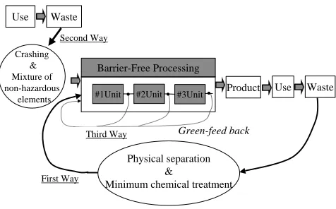
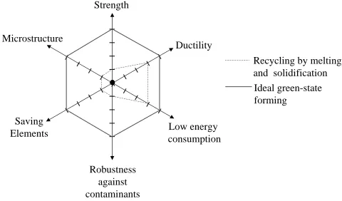
(2) 316. T. Aizawa, T. Luangvaranunt and K. Kondoh Strength. Table 1 List of TMR and P-TMR for aluminum, iron and silicon. Al. Microstructure. Fe. Si. Ductility Recycling by melting and solidification Ideal green-state forming. Saving Elements. Low energy consumption Robustness against contaminants. Fig. 2 Proof of reliability as an industrial material to be selected.. is necessary to make microstructure control. At the presence of contaminants or additives, relatively large amounts of slag or dross are ejected from the remelting process. In the ideal green state forming, microstructure control with grain size refinement takes place during processing. No additive elements are necessary for improvement of microstructure; e.g. silicon is positively utilized for precipitation hardening. Even contaminant elements are actively utilized for solid-solution strengthening. Reduction of energy consumption is an issue for this green state forming to replace the conventional processing. In the present study, the solid state recycling process is proposed to realize the above system of the green-state forming. Aluminum–silicon alloy is employed to describe the general characteristics of this approach. Effect of in-process silicon particle size refinement on the mechanical properties is discussed together with the active use of iron contaminant to aluminum for precipitation strengthening of aluminum matrix. On the basis of the online monitored imposed energy, the energy consumption in the present processing is compared with that for the commercial mass-production. Through the above demonstrations, validity and effectiveness of the present processing is stressed as a promising EBM.. TMR (t/metal-t). P-TMR (Mt/y). TMR (t/metal-t). P-TMR (Mt/y). TMR (t/metal-t). P-TMR (Mt/y). 10. 0. 239. 0. 5. 1. 2912. 1. 4. 5. 15. 3. quires the highest energy consumption in the mass flow of aluminum. Hence, in order to increase the mass fraction of recyclable aluminum waste in the total mass flow, these aluminum wastes to be fed-back must be processed in the solid state. Considering the three ways of mass flow in Fig. 1 in the recycling of aluminum in the solid state, every unit in manufacturing and materials processing might well handle the high dense compact or the green-state materials except for the input and output. Different from the solidified materials, the green compact has sufficient flowability to be net-shaped into various products. Other recyclable wastes can be also mixed or sometimes alloyed with the green compact as an additive for strengthening the original aluminum. As shown in Fig. 3, the crushed chips and granules, or, the remelt blocks and agglomerates with various sizes and shapes are accepted as an input material. Hence, as the first and the second ways of mass routine, any physically separated and crushed chips can be fed to this green-state forming as input. In nature, various contaminants or impurities are inevitably included into this input. In this system, these materials are subjected to be in-process refinement and microstructure-control so that the highly dense compact or the green compact should be obtained as an intermediate material. This compact is further near-net shaped by warm-pressing and warm powder forging before final sinter-forging or surface modification. Any intermediate material ejected from each process before output remains green-state so that it can be fed-back to the input of this processing. 3. Solid State Recycling of Aluminum Alloy. 2. Ideal System Towards Dematerialization of Aluminum Alloys As reported in Ref. 4), total material requirement (TMR) for mining and smelting aluminum (TMR-Al) from an ore is 10.0 t/metal-t. That is, 10 ton rocks, soils or other matters must be shoveled out from the earth to yield 1 ton metal aluminum. With increasing the total amount of raw aluminum in use, TMR for production of aluminum or P-TMR-Al drastically increases: e.g. P-TMR-Al reaches 239.0 Mt/y for aluminum. Hence, in parallel to low-TMR material selection, total amount of materials in use must be reduced as low as possible in the ideal system towards dematerialization. Additive elements are also necessary to strengthen pure aluminum for industrial use. Even in this stage, any elements must be prohibited to use when they increase TMR or P-TMR. Table 1 shows a list of TMR and P-TMR for Al, Fe and Si. Use of low-TMR Fe and Si for strengthening is adaptive to dematerialization. In addition, the energy consumption for recycling must be also reduced as possible. In the cascade-type recycling, smelting and remelting of the aluminum rods re-. The developed solid state recycling process is a typical green-forming or environmentally benign manufacturing for aluminum alloys. Bulk mechanical alloying (BMA) process plays a main contribution to this solid state recycling as illustrated in Fig. 4. After mechanically crushing the recyclable waste parts and members and chemically cleansing them, ascrushed chips, as-separated platelets or agglomerates or granules can be accepted as a starting material to BMA. In other words, different from the conventional P/M (Powder Metallurgy) processes, no powders need to be prepared for forming and sintering to products. As had been theoretically and experimentally demonstrated in Refs. 5–10), the above starting materials are subjected to severe plastic deformation and flow in the repetitive manner during BMA. As illustrated in the pass schedule in Fig. 4, the starting materials are compressed to high dense compact with the relative density of approximately 80% or more, and the cyclic load is applied to this dense compact with the relatively high density kept constant. This cyclic loading was scheduled by the automatic computer control to have two compression.
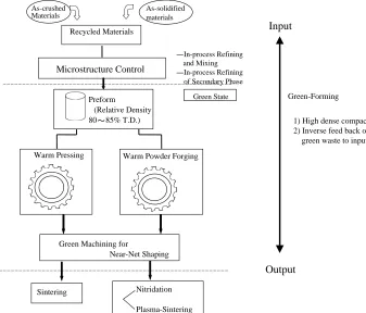
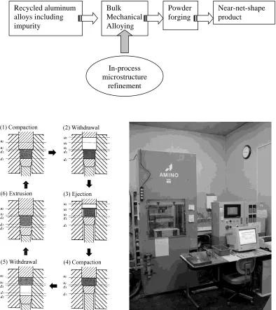
(3) Solid State Recycling of Recyclable Aluminum Wastes with In-Process Microstructure Control. 317. As-solidified materials. As-crushed Materials. Input. Recycled Materials. Microstructure Control. In-process Refining and Mixing In-process Refining of Secondary Phase Green State. Preform (Relative Density 80 T.D.). Warm Pressing. Green-Forming 1) High dense compact 2) Inverse feed back of green waste to input. Warm Powder Forging. Green Machining for Near-Net Shaping. Output Sintering. Nitridation Plasma-Sintering. Fig. 3. Green-state forming as one of the most promising barrier-free processing for non-ferrous materials.. modes and one forward extrusion mode. In the first compression mode, the current density of processed compact is reset to have the prescribed relative density. Severe shear strains are applied to this dense sample in the forward extrusion mode. In this process, each constituent matter can be plastically deformed and sometimes fractured to fragments. In particular, the secondary phase embedded in the matrix can be easily broken into fine particles in the matrix. These deformed constituents and fragments are recombined to the original dense compact in the second compression mode. Although this cyclic process requires seven seconds per a cycle, every process automatically takes place at room temperature in the inert gas atmosphere only with increasing the number of cycles (N). In the present experiment, the mechanical chips were utilized as a model of recyclable waste and Si powders with the average diameter of 20 µm was put into them in order to yield high Si-content aluminum alloys for automotive parts. Figure 5 shows mechanical chips machined from the solidified Al–12 mass%Si alloy block. As observed in the SEM micrograph, the Si-particulate in a chip is large and irregularly shaped so that the original microstructure is inadequate as an industrial structural material. In order that this Si should play as a strengthening particulate, this microstructure must be modified in-process to house the uniformly distributing fine Si-particles. In parallel with the above homogenization and refinement of Si-particles, the yielded product must have sufficiently high density to be net-shaped to final product. Figure 6 shows the solid-state recycled compact via bulk mechanical alloying with the relative density of about 80%. Even when N = 400, the silicon particle was reduced to under 5 µm and these fine Si-particles distributed uniformly. in the compact. Figure 7 depicts the forged Al-Si billet by using the sinter-upsetting. Full densification was attained at T = 673 K for 10 min. No significant particle growth was seen in the SEM micrograph. Hence, the highly dense compact created via BMA can be easily net-shaped to lightweighed automotive parts by changing the final die-set. 4. Case Studies for Discussion Effect of iron contaminants and Si-particle refinement on the in-process strengthening is discussed together with evaluation on the energy consumption in this processing. 4.1 Effect of iron contaminants on the in-process strengthening Even after physical separation and chemical cleansing, the recyclable wastes have their own contaminants. In case of solid-state recycling of aluminum alloys, iron is thought to be a main contaminant: e.g. iron is inevitably included in a recycled aluminum alloy when recycling the aluminum-alloy pulltop with a steel can. While, as had been reported in Ref. 11), aluminum can be strengthened by formation of solid solution or intermetallic precipitates. Hence, if the solid solubility of iron into aluminum is enhanced or precipitates are in-process formed by using the bulk mechanical alloying, this contaminant can be utilized as a strengthening component in the solidstate recycling. As a virgin material, this kind of Al–Fe alloys is attractive for strengthening the aluminum matrix, since it possesses high specific strength for typical aluminum alloys. The point to be noted is that there is very little solid solution between these two metals. Hence, Al–Fe alloys can be produced.
(4) 318. T. Aizawa, T. Luangvaranunt and K. Kondoh. Recycled aluminum alloys including impurity. Bulk Mechanical Alloying. Powder forging. Near-net-shape product. In-process microstructure refinement. Fig. 4 Solid-state recycling process via bulk mechanical alloying for nonferrous materials.. Fig. 5 Typical starting materials: mechanical chips of Al–Si blocks.. only in solid state by mechanical alloying (MA),11, 13–16) severe plastic deformation by torsion,17) and rapid solidifica-. tion processing (RSP).12) Microstructure of an Al–Fe alloy depends greatly on the atomic percent of Fe, and the processing method. Various authors reported dissolution of Fe up to 4.5 atomic percent into FCC Al-matrix by both MA and RSP. Higher amount of Fe induces formation of amorphous phase. The alloy turns into a complete amorphous phase for Fe concentration higher than 25 percent. After heat treatment of the alloy, stable intermetallic compounds of Al and Fe are precipitated.14) These precipitates are believed to contribute to the high temperature stability of the alloys.11) Al–Fe alloys produced by RSP show a rapid coarsening of Al–Fe precipitates at high temperature; consequently resulting in the breakdown of strengthening mechanism of the alloy.11) Mechanical alloying by ball milling/attrition can produce Al–Fe alloy, but typical processing time is in the order of tens of hours. Ratio of ball to powder must be high enough for effective fragmentation and welding of the powder mixture to induce alloyment. This leads to the inefficiency and long processing time. After alloyment stage, the produced powder must be heat treated.
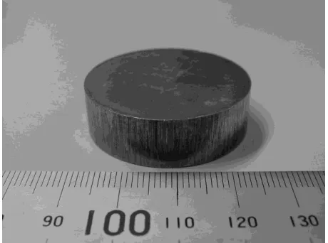
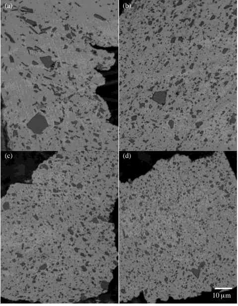
(5) Solid State Recycling of Recyclable Aluminum Wastes with In-Process Microstructure Control. Fig. 6 High-dense powder compact with the relatively density over 80%T.D.. Fig. 7 Full-dense bullet sinter-forged from the high-dense powder compact.. to precipitate the intermetallics. In addition to demerits for practical processing, the above state-of-the-art technologies are never robust to iron contaminants to aluminum. This is mainly because (1) contaminants are always shaped irregular and relatively large-sized, (2) contaminants heterogeneously distribute in the recyclable waste, and (3) powders with intermetallic precipitates are too hard to make working. In the bulk mechanical alloying, refinement with homogeneous mixing takes place to yield highly dense Al–Fe alloy compact from the contaminated aluminum block, chips or granules by iron or steel. In the following experiment, the powder mixture of pure atomized Al (33 µm in mean size, 99.8% purity) and Fe (70 µm in mean size, 99.5% purity) was employed as a model contaminated recyclable waste. Commercial die-wax type L of an amount equivalent to 0.2 mass% was mixed with the input material as a lubricant to reduce friction loss. The die was forced cool to keep the temperature under 333 K (or 60◦ C). Highly dense, green compact after BMA was analyzed by optical microscopy and XRD. Vickers hardness was measured as a way to estimate the strength of the produced alloys. Microstructure evolution for Al–4 mass%Fe alloy after 200 and 400 BMA cycles is depicted in Fig. 8. Fe particles progressively dissolute into Al matrix, as BMA continues to. 319. higher number of cycles. The difference in atomic diameter of Al (0.28636 nm) and Fe (0.24824 nm) is 13%. Hence, according to Hume-Rothery rule, solid solution can be formed but difficult. The observed disappearance of Fe in the matrix does not prove the solid solution formation of Al (Fe). In fact, XRD result in Fig. 9 shows precipitation of Al–Fe intermetallics, specifically Al13 F4 , Al5 Fe, and AlFe3 after BMA for 400 cycles. These intermetallic compounds are formed in situ, without the need of heat treatment. It is difficult to accurately see the peak shift of Fe or Al because of the overlapping between Al and Fe peaks. Then, the iron contaminating aluminum is thought to be partially changed to Fe-solute in the aluminum matrix and to be partially reacted into Al–Fe intermetallic precipitates. The latter fine precipitates distributed homogeneously in the matrix, since no precipitate was seen in EPMA. Vickers hardness of the Al-matrix indicates progressive hardening as shown in Fig. 10. The hardening of Al matrix is in general due to several factors, including work hardening, solid solution of Fe and precipitation of Al–Fe intermetallics. Taking σy = HV /3, a rough estimate of the yield strength of Al–4 mass%Fe alloy produced after 400 BMA cycles is 340 MPa.11) Since the yield of stress of pure aluminum is about 35 MPa, this strengthening is attributed not only to grain size refinement but also to precipitation hardening by the above Fe–Al intermetallic compounds. 4.2 Particle size refinement of Si In the Al–Si alloy, particle size refinement of Si particles and their homogeneous distribution in the matrix must be a key to make in-process strengthening via BMA. As shown in Fig. 11(a), the initial Si particle size was 20 to 30 µm in the mechanical chip. With increasing the number of cycles (N) in Fig. 11, Si particle size was reduced and the refined particles distribute in the matrix. As had reported in Ref. 9), reduction of the largest Si particle becomes important in the precipitation hardening. Figure 12 depicts the monotonic decrease of the largest Si particle size with increasing the number of cycles. Up to N = 100–200, the Si particle size was significantly reduced while it gradually decreases with N for N > 500. This implies that the silicon particles are fractured with plastic flow of aluminum matrix by application of cyclic loading in BMA in the initial stage, and, that finer Si particles should only reduce their size reluctantly even with increasing N for N > 500. 4.3 Energy consumption of the solid-state recycling Different from the conventional P/M-route processes, the mechanically imposed energy can be calculated and on-line monitored to the personal computer through the process computer. Figure 13 shows a typical variation of imposed energy per a cycle with increasing the number of cycles. At the pointed positions by arrows in Fig. 13, additional liquid wax was added to the processed samples to reduce the frictional work loss. Hence, the up-down variation of the imposed energy comes from the exaggerated frictional loss with increasing the number of cycles. Subtotal of imposed energy without the above friction loss was estimated to be 11.0 kJ/cycle. Applying the same pass schedule as shown in Fig. 4 to BMA without samples, the monitored energy provided us the con-.
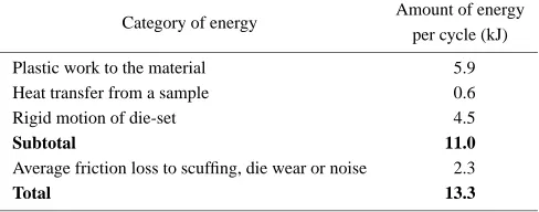
(6) 320. T. Aizawa, T. Luangvaranunt and K. Kondoh. Fe-Particles. Fe-Particles. 200. 200. 0 cycle. 200. 60 cycles. 200. 200 cycles. 400 cycles. Fig. 8 Refinement of iron contaminant via bulk mechanical alloying.. (a). (b). (c). (d). Intensity. Fe Al Intermetallics. 30. 40. 50. 60. 70. 80. Diffraction angle, 2 Fig. 9 XRD profiles of the processed high dense sample with Fe contaminants after 400 cycles in BMA.. Vicker Hardness (Hv 0.49 N). 140 120 100 80. 10 m 60. Fig. 11 Variation of microstructure for the in-processed Al–Si alloy with increasing the number of cycles: (a) as-received mechanical chip, (b) BMA 100 cycles, (c) 200 cycles, and (d) 500 cycles. Si-particulate was gradually refined in the aluminum matrix with increasing N.. 40. H = 41.3563 + 7.2706N. 0.3672. 20 0. 100. 200. 300. 400. Number of BMA Cycle, N. Fig. 10 Monotonic strengthening of aluminum compact with iron contaminants with increasing the number of cycles.. tribution of rigid motion to the imposed energy. Through the heat transfer analysis, the heat loss can be estimated in large. Table 2 lists each category of energy consumption and estimated energy. Only 45% of total energy is used for plastic work to sample materials in the present processing. Assuming that the targeting largest Si-particle size is 5 µm, the necessary number of cycles is 200. Since a sample with. 20 g can be processed in the present BMA system, the total plastic work becomes 59 kJ/g. This value is comparable to the total energy consumption in the commercial P/M process from atomizing to presintering for dense compact. Hence, the present solid-state recycling has the same or higher potential to save the energy consumption as or than the commercial mass-production by reducing the energy losses..
(7) Solid State Recycling of Recyclable Aluminum Wastes with In-Process Microstructure Control 40. Largest Si Particle Size, m. 35 30 25 20 15 10 5 0 0. 500. 1000. 1500. 2000. Number of BMA Cycle, N. Fig. 12 Monotonic decrease of Si particle size with increasing the number of cycles.. Energy Consumption per Cycle, kJ. 20. 18. 321. in the grade of 1xxx used for electrical parts can be reused for input of this process. Second, pure silicon waste from semi-conductive fabricator can be also reused as an additive to Al–Si alloys in BMA. Morphology-free processing is favored for broadening the silicon selection: wafers, rods, powders, blocks or granules can be accepted as a silicon source for this alloy. Robustness to iron contaminants can also afford to broaden the material selection for aluminum. This wide material selection completely reduces TMR for input materials to processing and links a new relation among different industries with a new material flow. Except for the final sinter-forging to make net-shaping to automotive parts, every process in the solid-state recycling can be performed in green or with adaptive manner to greenforming style. Through further demonstration, this innovation in recycling technologies must grow to a standard for solid state recycling with in-process improvement of mechanical properties. Acknowledgements. 16. Intimate discussion with members of the research committee on the Barrier-Free Processing was helpful to promote the present study. This work was financially supported by the National Project on “Barrier-Free Processing of Materials for Life-Cycle Design for Environment (Barrier-Free Processing for DfE)” from STA (Science and Technology Agency), Japan.. 14. 12. 10. 8 0. 50. 100. 150. 200. 250. REFERENCES. Number of BMA Cycle, N. Fig. 13 Energy consumption per a cycle for Al–12% Si alloys produced by bulk mechanical alloying. Table 2 Categorization of energy consumption in the present solid-state recycling. Category of energy. Amount of energy per cycle (kJ). Plastic work to the material Heat transfer from a sample Rigid motion of die-set Subtotal Average friction loss to scuffing, die wear or noise Total. 5.9 0.6 4.5 11.0 2.3 13.3. 5. Conclusion The solid-state recycling has become an effective and powerful methodology to realize the green-state forming from the recyclable wastes to the automotive parts. Al–12% Si alloy, highly dense compact with refined grain size can be directly formed from the mixture of mechanical chips made from the solidified blocks. This success stimulates the movement toward minimization of waste emission. First, pure aluminum. 1) Handbook of Environmental Conscious Materials, (McGraw Hill, 2001) (in press). 2) M. Mabuchi, K. Halada and T. Aizawa: Mater. Trans. 43 (2002) 285– 291. 3) T. Murata: Private Communication (2001). 4) K. Halada: Key Note Speech of JIM Symposium. (2001, Sep.). 5) T. Aizawa, K. Tatsuzawa and J. Kihara: J. Faculty of Engineering, University of Tokyo. XLII (1993) 261–279. 6) O. Kobayashi, T. Aizawa and J. Kihara: Mater. Trans., JIM 37 (1996) 1497–1504. 7) T. Aizawa, J. Kihara and D. J. Benson: Mater. Trans., JIM 36 (1995) 138–149. 8) T. Aizawa, T. Luangvaranunt and K. Kondoh: Proc. ECOMATERIALS, (Metallurgical Society of Canada, 2000, Ottawa) 273–288. 9) T. Aizawa, T. Luangvaranunt and K. Kondoh: J. Japan Inst. Metals 65 (2001) 581–588. 10) K. Kondoh, T. Luangvaranunt and T. Aizawa: Mater. Trans., 42 (2001) 1254–1257. 11) X. P. Niu, L. Froyen, L. Delaey: J. Mater. Sci., 29 (1994) 3724–3732. 12) J. C. Ehrstrom: Mater. Sci. Eng. A. 186 (1994) 55–64. 13) D. K. Mukhopadhyay, C. Suryanarayana and F. H. Froes: Scr. Metall. Mater. 31 (1994) 333–338. 14) D. K. Mukhopadhyay, C. Suryanarayana and F. H. Froes: Metall. Mater. Trans. A 26 (1995) 1939–1946. 15) V. I. Fadeeva and A. V. Leonov: Mater. Sci. Eng. A A206 (1996) 90–94. 16) B. Huang, K. N. Ishihara and P. H. Shingu: Mater. Sci. Eng. A A231 (1997) 72–79. 17) O. N. Senkov and F. H. Froes: Nanostruc. Mat. 10 (1998) 691–698..
(8)
Figure
+4
Related documents
