Determination of Macro-Contact Angle and Line Tension at High Temperatures
for Au/Al
2O
3System at 1373 K Using a Micro-Scale Wetting Method
Joonho Lee
1, Kazuki Morita
2and Toshihiro Tanaka
1 1Department of Materials Engineering and Processing, Osaka University, Suita 565-0871, Japan 2Department of Materials Engineering, the University of Tokyo, Tokyo 113-8656, Japan
The size effect of a drop on the contact angle was discussed for the Au/Al2O3system. As the size of the drop decreases, the shape of the drop closes to a sphere and the contact angle is obtained by the equation¼cos1ð1h=R
Max.Þ, whereis the contact angle between the drop
and substrates,his the height of the drop andRMax.is the maximum radius of the drop. The contact angle between liquid gold and alumina
polycrystalline substrates having the roughness of 0.141mmin RA number slightly increased as the sample size decreases to about 10mm, yielding 134and3:50107N as the macro-scale contact angle and the line tension, respectively.
(Received September 4, 2003; Accepted October 6, 2003)
Keywords: metal, alloy, surface; contact angle, micro-wetting, Young’s equation, Laplace equation
1. Introduction
A non-reactive liquid metal drop resting on a solid ceramic substrate exhibits a contact angle (generally higher than 90), which is determined by Young’s equation as described
by eq. (1).1)
LVcos¼SVSL ð1Þ
whereSV,SL,LVandare the surface tension of solid, the
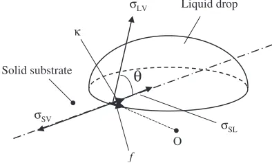
interfacial tension between solid and liquid, the surface tension of liquid and the contact angle, respectively. (S,Vand Lrefer to solid, vapor and liquid, respectively.) Equation (1) has been generally accepted to be valid for a macro-scale liquid drop. However, precisely, eq. (1) should be re-written by eq. (2),2) because solid, vapor and liquid phases are divided not only by faces but a line as shown in Fig. 1.
LVcos¼SVSL=r ð2Þ
whereandrare the line tension and the radius of the liquid drop. Equation (2) is obtained for a horizontal solid surface by assuming that the dependence of the line tension on curvature is negligible. For a large drop (having a large curvature radius of the triple line), the line tension term in eq. (2) becomes small enough to be ignored, yielding the
classical Young’s eq. (1). Thermodynamically, the line tension is defined as the work of formation per unit length of a new line, so that it should have a positive value.3) Experimentally, however, the thermodynamic equilibrium contact angle is difficult to obtain, because of the absence of diffusional equilibrium for solids where the chemical potential gradients near the surface are at equilibrium.3) Therefore, we usually observe that the preceding and receding contact angles are different.4,5) In addition, when some reactions are companied by mass transfer at the liquid/ solid interface, the contact angle generally decreases,6) establishing a mechanical equilibrium contact angle. In the situation of the mechanical equilibrium, the line tension is related to stretching energy and may have both positive and negative values.
There have been several reports on the line tension at room temperature7,8) (or slightly higher temperatures up to 616 K2)), but no researchers except Ueda et al.9) have reported on the line tension at much higher temperatures. Uedaet al., however, chose a reactive system (Fe/Al2O3 at
1873 K in the atmosphere of various oxygen partial pressure), obtaining very high negative values as the line tension. It is believed that the measured values by Ueda et al. (for example,2:45103N in Ar-5%H2 atmosphere with Ti
getter) are the mechanical line tension, which may not equal to the thermodynamic line tension, and could have negative values as explained above.2,3)
In the present work, a micro-scale non-reactive liquid metal drop (gold) resting on a solid ceramic substrate (alumina) was investigated to determine the macro-scale contact angle and the line tension at high temperatures simultaneously.
2. Experimental
2.1 Materials and procedure
In the present work, in order to avoid any reactions which may affect the contact angle, gold and alumina were chosen as the liquid metal and the solid substrate, respectively. Chatainet al.10)presented that in the Au-O/Al2O3system the
surface tension and contact angle in macro-scale are constant
σLV
σSV
σSL
κ
Liquid drop
Solid substrate
θ
f
O
[image:1.595.68.265.609.729.2](1313) over the oxygen pressure ranging from1015 to
5104Pa at 1363 K. Noting that the surface tension and
contact angle for liquid metal decrease with increasing oxygen activity due to oxygen adsorption at the surface of the metal and the interface between the metal and the substrate, it is expected that we can measure the accurate contact angle between liquid and solid without oxygen contamination using the Au/Al2O3system. (SVSLterm is constant in eq. (2).)
In the present investigation, the contact angle between liquid gold and alumina substrates was measured at 1373 K (practically in the temperature range between
13631376K) in a purified argon gas atmosphere. A piece of gold chip weighing 0:00200:0125g cut from a high purity gold wire (99.99%) was placed on the high purity alumina (99.6%) substrates. The roughness of the surface of the alumina substrates was measured with an atomic force microscopy analyzer before experiments, yielding 0.141mm
in the RA number. Experiments for size dependence were conducted with alumina polycrystalline, and additional experiments with (0001) and (1120) alumina single crystals faces were done to understand the effect of heterogeneity of polycrystalline substrates. The apparatus and experimental techniques are the same as described in our previous contribution.11)
2.2 Novel method determining micro-scale contact an-gle for a non-wetting system
2.2.1 Geometry of micro-scale drop
The contact angle of a micro-scale drop could be obtained by the height-width method using eq. (3) with information such as the height of a liquid drop (h) and the radius of the interface between liquid and solid (r).8,12)
¼2 tan1 h
r ð3Þ
However, from a vertical direction in a non-wetting system (90< <180), the contact angle cannot be determined,
because r cannot be measured (Usually, the micro-scale contact angle is determined from the vertical direction.11,12)). Although we could investigate a liquid drop from a horizontal direction, it is very difficult to determine the position of the triple line (or the length of r) in thresholding a captured image.
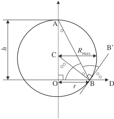
In order to determine the contact angle of a micro-scale drop in a non-wetting system, we suggest a new equation from geometric relation of a micro-drop as below. Here, due to such reasons described above, it is preferred to obtain the contact angle only with available and reliable data such as height (h) and the maximum radius (RMax.) in Fig. 2. Since
(=OCB+=CBO) and (=CBO+=DBB0) equal to 90,=
CBO
equals to=DBB0(¼180). Accordingly,
cos¼ cosð180Þ ¼1 h
RMax.
ð4Þ
Equation (4) can be re-expressed by eq. (5).
¼cos1 1 h
RMax.
ð5Þ
2.2.2 Application limit of new method
From a simulation study on the size effect of liquid gold on
the spherical geometry, we can obtain the application limit of eq. (5). The profile of a drop is drawn from Laplace equation described as eq. (6).
1
R1
þsin
x ¼
2
Ro
þzg
ð6Þ
whereR1,Ro,,x,z,,gandare the curvature radius at a
point of interest, the curvature radius at the apex, the turning angle, the horizontal position of interest, the vertical position of interest, the difference in densities between the drop and the surrounding phase, the gravitational constant and the surface (or interface) tension. Details are shown in liter-atures.13–15)
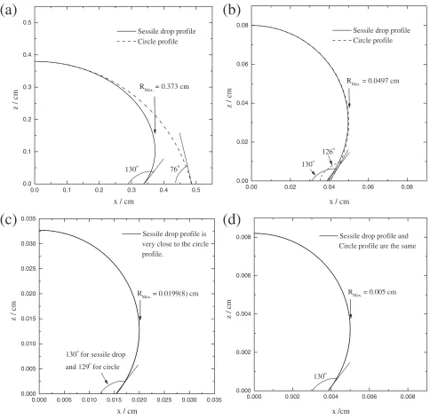
The solid curves in Figs. 3(a)(d), respectively, show the profiles of the drops of liquid gold for Ro¼0:5, 0.05, 0.02
and 0.005 cm. The contact angle for those profiles was set as 130. The values of the density and the surface tension of liquid gold are quoted from the literatures: 17.36 g/cm3and 1160 mN/m respectively at 1373 K.16)The dotted curves in Fig. 3 indicate the circle profile obtained by adjusting center position of the circle to have the curvature radius at the apex. As can be seen from Fig. 3, the shape of the liquid gold approaches a complete circle with a decrease in the drop size, yielding no difference between the two angles. In the present work, as a shape parameter () of a liquid drop, the difference between the curvature radius at the apex and the maximum radius of a sessile drop was defined.
¼RoRMax.
Ro
100ð%Þ ð7Þ
From Fig. 3(c), we can conclude that the application limit of eq. (5) is when the shape parameter is less than 0.1%. In other words, if a micro-scale liquid gold drop (less than about 400mmin diameter) is investigated, the shape is almost close to a sphere, and the contact angle can be determined by eq. (5).
r
O
A
C
B
B’
D
h
R
max.
Fig. 2 Geometric relation of a micro-scale drop to determine contact angle
=
[image:2.595.327.525.72.279.2]3. Results and Discussion
3.1 Effect of size on contact angle Equation (2) may be rewritten as eq. (8).
cos¼cos1 ð=LVÞ
1
RMax.
ð8Þ
where1is the contact angle whenRMax.! 1. Then, if we
plotcosversus1=RMax., we can obtain a linear relationship,
yielding the macro-scale contact angle and the line tension from the intercept with the vertical axis and the slope, respectively. Figure 4 shows the measurements ofcoswith respect to the reciprocal value of the maximum radii of liquid gold. Using a linear regression analysis, we obtained 134 and3:50107N for the macro contact angle and the line tension, respectively. The macro-scale contact angle of the present work shows reasonable accordance with the previous
0.0 0.1 0.2 0.3 0.4 0.5
0.0 0.1 0.2 0.3 0.4 0.5
130o 76o RMax.= 0.373 cm Sessile drop profile Circle profile
x / cm
z / cm
0.00 0.02 0.04 0.06 0.08
0.00 0.02 0.04 0.06 0.08
130o 126o
RMax. = 0.0497 cm Sessile drop profile Circle profile
x / cm
z / cm
0.000 0.002 0.004 0.006 0.008
0.000 0.002 0.004 0.006 0.008
130o
RMax. = 0.005 cm Sessile drop profile and Circle profile are the same
x /cm
z / cm
0.000 0.005 0.010 0.015 0.020 0.025 0.030 0.035 0.000
0.005 0.010 0.015 0.020 0.025 0.030 0.035
130o for sessile drop
and 129o for circle
RMax. = 0.0199(8) cm Sessile drop profile is very close to the circle profile.
x / cm
z / cm
(a)
(b)
(c)
(d)
Fig. 3 Calculated shape of a pure gold sessile drop on an alumina substrate at 1373 K, where the surface tension is 1160 mN/m, the density is 17.36 g/cm3and the contact angle is 130.R
oare 0.5, 0.05, 0.02 and 0.005 cm in Figs. (a), (b), (c) and (d), respectively.
0 2 4 6 8 10
-0.85 -0.80 -0.75 -0.70 -0.65 -0.60 -0.55
Polycrystalline (0001) (1120)
κ = 3.50 x 10⁻⁷ N θ' = 134.3o
cos
θ
/
-1/RMax. / 104 m-1
[image:3.595.57.541.73.545.2] [image:3.595.318.537.593.757.2]measurements (131140).5,10,17,18) The obtained line ten-sion is considerably reasonable, because usually the line tension is reported not to depend strongly on materials, having a value between1012and106N.5)
The line tension obtained in the present work is very small compared with the surface or interfacial tension. Hence, we may expect that the interfacial tension obtained from Young’s equation in macro scale is applicable to nucleations or nano-particle modeling. Recent reports by Tanaka et al.19,20) and Lee et al.21)
employed the surface and interfacial tensions obtained from Young’s equation in macro-scale for nano-particles larger than 10 nm in diameter, which are considered reasonable based on the present results.
In Fig. 4, some results of micro-scale contact angle with (0001) and (1120) alumina single crystal faces are plotted for comparison. Even though measured values show large scattering, it is noteworthy that the contact angle on (0001) face is lower than that on (1120). Thus, we may expect that the heterogeneity of the surface energy of alumina poly-crystalline may affect the measurements of the contact angle. It is also well recognized that a large axisymmetric shape could be obtained with smaller liquid drop,22) and micro-scale liquid drop is more likely to form an axisymmetric drop. Accordingly, the macro-scale drop may lose the axisymmetric shape. In the present work, the macro-scale gold drop weighing 0.1438 g on an alumina polycrystalline substrate was investigated, resulting a non-axisymmetric shape of liquid gold drop. (Right (141) and left (135)
contact angles in a direct observation slightly differ with each other.) Using Young-Laplace fitting method,13,14)we obtain the contact angle 143, which is slightly higher than the
present result (134). Accordingly, the difference in the
measured values by micro- and macro-scale is considered caused by the non-axisymmetric shape of liquid drop in macro-scale.
3.2 Effect of capillary constant on shape parameter Equation (5) is valid for a spherical liquid drop, so that it is important to know the limit of the available drop size. Recently, Lee et al.15) have shown that as the capillary constant (C.C.¼= in eq. (6)) increases, the profile of liquid metal drop is more affected by gravitational force at a constant size, and the errors in surface tension measurements decreases. Accordingly, the capillary constant is considered to determine the shape of liquid drop. Figure 5 shows the simulated results of the shape parameter as a function of the curvature radius at the apex (Ro). In the simulation, Bi, Sn,
Cu and Co was used, having different capillary constants. (Table 1) It is considerable that the shape parameter () and the curvature radius at the apex (Ro) have a linear relationship
in logarithmic scale with a constant slope regardless of metal species when Ro is less than 0.1 cm. Therefore, we may
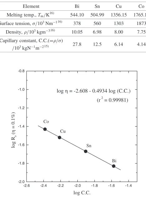
consider that the limit of the available drop size could be expressed only by the capillary constant. In Fig. 6, the curvature radius in logarithmic scale at a constant shape parameter (limit of application of eq. (5),¼0:1) is shown as a function of the capillary constant in logarithmic scale. The linear regression yields
logRoð¼0:1Þ ¼ 2:6080:4934 logðC.C.Þ ð9Þ
From this relationship, if we know the capillary constant of metal or alloy, we can estimate the size of drop to form a spherical shape.
4. Conclusions
In this paper, the size effect of drop on the contact angle between liquid gold and alumina substrates was discussed by
0.01 0.1 0.01
0.1 1 10
Sn Bi Cu Co
Curvature radius at the apex, Ro / cm
Shape parameter,
η
/ %
Fig. 5 Relationship between the shape parameter of the liquid metal drop and the radius at the apex.
Table 1 Capillary constant of pure metals at the melting temperatures.
Element Bi Sn Cu Co
Melting temp.,Tm/K16) 544.10 504.99 1356.15 1765.15
Surface tension,/103Nm116) 378 560 1303 1873
Density,/103kgm316) 10.05 6.98 8.00 7.75
Capillary constant, C.C.(==)
27.8 12.5 6.14 4.14
/103kgN1m215)
-2.6 -2.4 -2.2 -2.0 -1.8 -1.6 -1.4 -2.0
-1.8 -1.6 -1.4 -1.2 -1.0 -0.8
log η = -2.608 - 0.4934 log (C.C.)
(r2 = 0.99981)
Bi Sn
Cu Co
log C.C.
log R
o
(
η
= 0.1%)
[image:4.595.323.529.70.270.2] [image:4.595.308.542.333.648.2]using Young’s equation considering the line tension. From the relationship between the micro-scale contact angle and the reciprocal ofRMax., we obtained 134and3:50107N
for the macro-scale contact angle and the line tension, respectively. Here, the micro-scale contact angle was determined with a new equation ¼cos1ð1h=R
Max.Þ.
From the simulation results with Laplace equation, the limit size of drop was expressed as a function of the capillary constant.
Acknowledgements
Authors are grateful to Drs. S. Ueda and J.-G. Lee for their helpful discussion on the line tension.
REFERENCES
1) T. Young: Miscellaneous Works, Ed. by G. Peacock, J. Murray, London,1(1805).
2) A. I. Rusanov: Surf. Sci. Rep.23(1996) 173-247.
3) A. I. Rusanov: Colloids and Surfaces A: Physicochemical and Engineering Aspects156(1999) 315-322.
4) T. Tanaka, S. Hara and M. Okamoto: Tetsu-to-Hagane´,84(1998), 25-30.
5) B. Gallios:Ph.D.Thesis, (Carnegie Mellon University, Pittsburgh, PA
1980).
6) J. Lee and K. Morita: ISIJ Int.,44(2004) to be published. 7) A. Marmur: J. Colloids Interface Sci.186(1997) 462-466.
8) K. W. Stockelhuber, B. Radoev and H. J. Schulze: Colloids and Surfaces A: Physicochemical and Engineering Aspects156(1999) 323-333.
9) S. Ueda, H. Shi, X. Jiang, H. Shibata and A. W. Cramb: Metall. Mater. Trans. B.34B(2003) 503-508.
10) D. Chatain, F. Chabert, V. Ghetta and J. Fouletier: J. Am. Ceram. Soc. 76(1993) 1568-1576.
11) J. Lee and K. Morita: ISIJ Int.42(2002) 588-594.
12) R. Wang, N. Morihiro, T. Tokuda and M. Kido: J. Japan Inst. Metals66 (2002) 808-815.
13) Y. Rotenberg, L. Boruvka and A. W. Neumann: J. Colloid Inter. Sci.93 (1983) 169-183.
14) I. Jimbo and A. W. Cramb: ISIJ Int.32(1991) 26-35.
15) J. Lee, M. Nakamoto and T. Tanaka: CAMP-ISIJ16(2003) 1016. 16) T. Iida and R. I. L. Guthrie:The Physical Properties of Liquid Metals,
(Clarendon Press, Oxford, 1993) 6-7, 71, 134.
17) I. Rivollet, D. Chatain, C. Chatillon and N. Eustathopoulos: Acta Metall.35(1987) 561-567.
18) J. V. Naidich:Progress in Surface and Membrane Science, Ed. by D. A. Cadenhead and J. F. Danielli, (Academic Press, London, U.K. 1981). 19) T. Tanaka and S. Hara: Z. Metallkd.92(2001) 467-472.