University of Warwick institutional repository: http://go.warwick.ac.uk/wrap
This paper is made available online in accordance with
publisher policies. Please scroll down to view the document
itself. Please refer to the repository record for this item and our
policy information available from the repository home page for
further information.
To see the final version of this paper please visit the publisher’s website.
Access to the published version may require a subscription.
Author(s): Higgins, M.D. Green, R.J.and Leeson, M.S.
Article Title: Optical Wireless for Intravehicle Communications: A
Channel Viability Analysis
Year of publication: 2011
Link to published article:
http://dx.doi.org/10.1109/TVT.2011.2176764
Publisher statement: "(c) 2011 IEEE. Personal use of this material is
permitted. Permission from IEEE must be obtained for all other users,
including reprinting/ republishing this material for advertising or
Optical Wireless for Intra-Vehicle Communications:
A Channel Viability Analysis
Matthew D. Higgins,
Member, IEEE,
Roger J. Green,
Senior Member, IEEE,
and Mark S. Leeson,
Senior Member, IEEE
Abstract—This paper provides an initial analysis into the viability of implementing an Optical Wireless system for intra-vehicle communications. Based upon the use of a simple, lin-early scalable infrared LED transmitter, the results for received power, bandwidth and RMS delay spread are shown at over 3000 locations within a Sports Utility Vehicle. Several of these locations, including the rear passenger seats, backs of the driver and front passenger seats and dashboard are highlighted as having advantageous channel characteristics for the deployment of mobile communications equipment, audio visual displays, computer consols or human-vehicle interface devices such as air conditioning or window controllers. Within the vehicle, received powers of up to 49µW with associated bandwidths ≥300MHz and negligible RMS delay spread can be achieved at several locations. The analysis presented, as the first of its type, will provide the foundations for a larger investigation into intra-vehicular communications including the optimisation of transmitter-receiver configurations and the advancements of upper layer protocols that can exploit specific channel charac-teristics for high end user quality of service.
Index Terms—Optical Wireless, Wireless LAN, VANET, Chan-nel Model.
I. INTRODUCTION
T
HE number of interconnected electronic devices withinmodern vehicles has been rapidly growing for several years now and will continue to do so in the future. Vehicle manufactures are moving to differentiate their products not only on pure mechanical and aesthetic characteristics but also on their electronic capabilities such as navigation, electronic safety devices, fly-by-wire technologies and Audio Visual (AV) entertainment solutions [1], [2]. Furthermore, the passen-gers of the car are requiring that they stay ‘connected’ whilst on the move via mobile devices and computers. However, this growth in the number of electronic devices increases the complexity and cost of the design and manufacturing. Furthermore, the increase in the necessary wiring reduces reliability and fuel efficiency through increased weight of the vehicle.
One possible way of mitigating these effects of increased ve-hicular electronics is to adopt wireless communications where possible. An interesting and emerging [3] branch of available wireless communications techniques is Optical Wireless (OW), which combines the mobility of radio frequency wireless communications with the high bandwidth availability of fixed
The authors are with the School of Engineering, University of Warwick, Coventry, CV4 7AL, UK.
E-mail:{m.higgins;roger.green;mark.leeson}@warwick.ac.uk
Manuscript version: 13/11/2011
optical communications [4]. In a recent review paper [5], it was shown that OW may provide a compatible solution to the concept of intra-vehicular communications, defined to be the process of irradiating the interior (or section) or the vehicle with infrared (IR) radiation to serve as the communication link between anything from simple user-vehicle interface devices such as window or air conditioning controllers, to more advanced devices associated with AV entertainment units or computer consoles.
However, before any OW based intra-vehicle communica-tion system is prototyped or developed, it is customary for a system designer to complete an accurate channel model and associated analysis, for which to the best of the authors knowledge, has not yet been presented in the literature. This paper serves to initiate such analysis in what is hoped to be a growing area, by presenting the first known channel characteristic results of received power, bandwidth and RMS delay spread within a vehicle. Based upon these results, a system designer should be able to use the values as a reasonable guide for their design parameters and furthermore it is hoped that for those readers whom have not yet considered OW as a viable option, to reconsider their position.
A Sports Utility Vehicle (SUV) has been chosen as the initial test case as it represents a reasonably high-end vehicle scenario: the thinking is that once the system has been evaluated and shown to be useful at this end of the vehicle market, the design concepts can then find their way into all classes and types of vehicle, including commercial types. Of course, there are particular challenges with all such vehicles, such as interior layout, trim, ratio of window-to-hard surface areas, types of fabric on seats and fabric distribution internally, in general, combined with their related optical- and infrared properties. There is also the distribution and types of optical sources to consider, and the layout of passenger seats.
0 0.2
0.4
0.6
0.8
1.0
1.2
1.4
1.6
0 0.5 1
.0 1 .5 2
.0 2 .5 3
.0 3 .5
0 0.5
1.0
1.5
x position(m)
y position(m)
z
p
o
si
ti
o
n
(
m
)
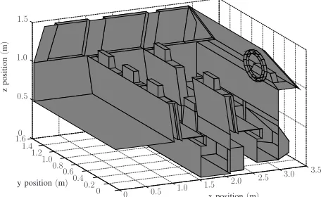
(a) Front facing view of the deployment structure with the driver side wall, windscreen and ceiling removed.
0 0.2
0.4
0.6
0.8
1.0
1.2
1.4
1.6
0 0.5
1.0
1.5
2.0 2.5
3.0
3.5
0 0.5
1.0
1.5
x position(m)
y position(m)
z
p
o
si
ti
o
n
(
m
)
[image:3.595.63.292.115.254.2](b) Rear facing view of the deployment structure with the driver side wall, rear windscreen, boot door and ceiling removed.
Fig. 1. The SUV structure for which the OW system is deployed within.
II. SYSTEMMODEL
A. Vehicle Environment
The internal structure of the SUV, comprising floor, ceiling, fascias, seats, steering wheel, arm-rests etc. can be seen in
Figure 1. It was formed though the arrangement of286planar
polygons producing a system environment that was as realistic as practically possible, including features such as angled foot-wells, recessed windows, bevelled edge seats and other potential ‘blind-spots’ found within modern vehicle interiors. The dimensions and overall shape, or topology, are not specific to a particular marque or model, but should provide the reader
with a reasonable familiarity to severalpopular SUV choices
currently in production. It should also be noted that, apart from the steering wheel and instrument control panel, the structure
is symmetrical in the xaxis aty= 0.8m allowing for simple
transposition of the results to a left hand drive version from the right hand drive version modelled here.
In previous works [6], [7] on the modelling of OW com-munication systems for indoor applications, it was typically assumed that all the surfaces within the system deployment environment exhibited a fully diffuse, ideal Lambertian reflec-tion profile. For this scenario, such an assumpreflec-tion cannot be
made as it is well known that glass, abundantly found within a vehicles interior, exhibits a specular reflection profile, i.e the reflection profile is dependant upon the radiations angle of incidence unlike the Lambertian model. Therefore, in this work, the Lambertian reflection model is superseded with the more advanced Phong [8] reflection model, for which, the
emitted or reflected radiation intensity profile,R(φ, θ), is given
by [9], [10]:
R(φ, θ) = PS
rd(n+ 1) cosn(φ)
2π +. . .
(1−rd)(m+ 1) cosm(φ−θ) 2π
(1)
Whereφ∈[0, π/2]andθ∈[0, π/2] are the angles of
obser-vation and incidence relative the surface normals respectively,
rd ∈ [0,1] represents the ratio of incident signal reflected
diffusely,m is the order of the specular component,n is the
order of the diffuse component and PS is the power of the
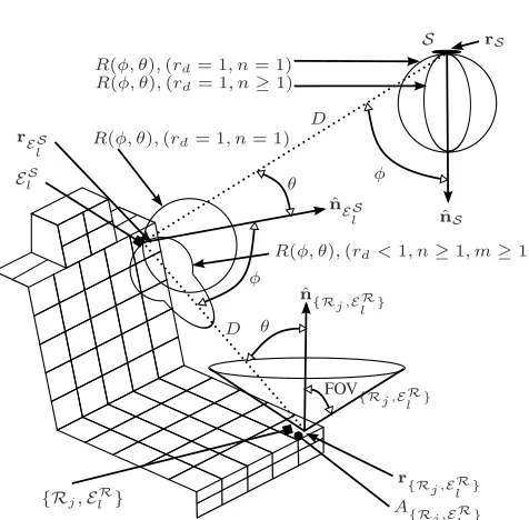
radiation to be emitted either at a given absolute wavelength or over the range of wavelengths should the device have a defined spectral width. Referring to Figure 2, the geometries with example generalised radiation profiles are shown for cases
when the reflection profile is either Phong (rd < 1, n ≥
1, m ≥ 1), high order Lambertian (rd = 1, n > 1) or
traditional pure Lambertian (rd = 1, n = 1). In order to
determine accurate values for m,n andrd in (1), along with
the reflectivity Γ ∈[0,1] of several common vehicle interior
materials, the open access Columbia-Utrecht Reflectance and Texture (CUReT) database [11] was employed.
From the databases 61 available materials, ‘Sample 4
-Rough Plastic’ is the most similar to typical fascia plastic used on car door interiors, window sills and dashboards. Through a Oren-Nayer fitting process [12], it was found that
the material exhibited a 0.6 reflectivity with96% of it being
diffuse. ‘Samples 8,18,19,42 and 44’, which represent the materials of Velvet, Thick Rug, Fine Rug, Corduroy, Linnen and Cotton respectively, are ideal candidates for representing the vehicles interior upholsteries. Via the same Oren-Nayer fitting process, the upholsteries reflectivity ranged between
0.12 and 0.57 for which the heavier samples, such as those
used on the car floor, having a lower reflectivity, and the finer materials, such as the thin fabric found on a car ceiling, having a higher reflectivity. Of these reflectivity values, the percentage of power contained within the diffuse component
ranged between 94% and 99%. Therefore, based upon their
measurements, and to reduce the simulation complexity, each of the fabrics and the fascia plastic will be assumed to be
fully diffuserd = 1, with their respective reflectivities shown
[image:3.595.57.285.311.451.2]TABLE I
REFLECTION PROPERTIES USED DURING SIMULATION
Material Γ rd m n
Glass 0.03 0 280 1
Fabric (Ceiling) 0.5 1 1 1
Fabric (Seats) 0.4 1 1 1
Fabric (Floors/Boot space) 0.3 1 1 1
Fascia Plastic 0.6 1 1 1
B. Source, Receiver and Reflector Model
The transmission source,S, in this scenario is considered to
be an IR LED located centrally upon the ceiling with position
vector rS = [1.6,0.8,1.45], orientated vertically downwards
with unit length orientation vectornˆS. The radiation emission
profile, R(φ, θ), with power PS, is assumed to be uniaxial
symmetric, with respect tonˆS, and ideal Lambertian as given
by (1) settingn= 1 andrd = 1.
In order to determine the suitability of the OW channel for communication purposes, and to determine where in the vehicle high levels of IR radiation with suitable bandwidth characteristics are located, it is necessary to model the
exis-tence ofJsingle element receiversRj. It is assumed that each
receiver is of the same specification such that Rj = Rj+1,
and this allows for the results in Section III to describe both a
system withJ receivers at multiple locations or one receiver
atJ locations without any loss of generality. To determine the
position and orientation of each J receivers (orJ locations)
each of the 286 planar polygons in Figure 1 was bilinearly
interpolated [13] at a resolution of10segments per meter (100
segments per square meter). Post interpolation, the resultant
locations of each of the J = 3006 receiver locations rRj,
was associated with a unit length orientation vector nˆRj
identical the respective surface normal of the original polygon,
an active optical collection area ARj = 1cm
2, and field
of view FOVRj = 45
◦, defined as the maximum uniaxial
symmetric incident angle of radiation with respect tonˆRj, that
will generate a current within the photodiode. The decision
to set ARj = 1cm
2 is based upon a desire to keep the
forthcoming results as generalised as possible, allowing for the comparison of the system performance presented here to be directly comparable to papers such as [14]. Moreover, due
the linearity of the channel, in the event using smaller ARj
values, the received power values should simply be scaled appropriately.
Given the definitions and material properties of the vehicles internal structure provided in Section II-A, each of the planar
polygons is interpolated bilinearly into L elements El at a
resolution of∆Ak, the desired number of elements per meter.
Based upon the interpolation, the resultant elements El, will
have an associated areaAEl= 1/∆A
2
k, unit length orientation
vector nˆEl determined from the normal vector of the original
non-interpolated plane at a position vector rEl. The element
will then behave as a receiver, ER
l with a hemispherical
FOV for which the incident power PER
l can be determined,
before acting as a sourceER
l , with a radiation emission profile
R(φ, θ), as given by (1) setting the parameters to the respective
properties of the element in Table I and with PS = ΓPER
l .
ˆ
nES l
φ R(φ, θ),(rd= 1, n= 1)
R(φ, θ),(rd<1, n≥1, m≥1)
θ
FOV{R j ,ERl } θ
ˆ
n{R j ,ERl } D
D ES
l
{Rj,ElR} rES
l
r{R j ,ERl } A{R
j ,ERl }
ˆ
nS φ
R(φ, θ),(rd= 1, n= 1)
R(φ, θ),(rd= 1, n≥1)
[image:4.595.79.271.126.187.2]rS S
Fig. 2. Source, receiver and reflector geometry, adapted from [14]
C. Impulse Response Calculations
The IR radiation incident upon a receiver Rj will be
the result of radiation emitted from the source S that has
propagated directly through an unobstructed LOS path, and/or
from the radiation that has undergone a finite number, k,
reflections off the internal surfaces of the vehicle. It has previ-ously been shown [14], [15] that for an intensity modulation, direct detection (IM/DD) channel, where the movement of the transmitter, receiver or reflectors within the environment are slow compared to the bit rate of the system, no multipath fading occurs, and, as such, can be modelled with as an LTI
channel with impulse response h(t;S,Rj)given by [14]:
h(t;S,Rj) = k X
k=0
hk(t;S,R
j) (2)
where hk(t,S,R
j)is the impulse response of the system for
the radiation undergoingkreflections between S andRj.
Assuming that the source S emits a unit impulse att= 0,
i.e settingPS = 1W, then the LOS(k= 0)impulse response
is given by the scaled and delayed Dirac delta function:
h0(t;S,R
j)≈R(φ, θ)
cos(θ)ARj
D V
θ
FOVRj
δ
t−D
c
(3)
where, with reference to Figure 2, D =||rS −rRj|| is the
distance between the source and receiver, c is the speed of
light,φandθare the angles betweennˆS and(rS−rRj)and
betweennˆRj and(rS−rRj)respectively.V(x)represents the
visibility function, whereV(x) = 1for|x| ≤1andV(x) = 0
otherwise.
The use of a 1W source, necessitated by the definition
characteristics and image size [17]. Given that at this stage of the investigation, where only generalised initial findings on viability are presented, the factors listed above will be design dependent such that the reader is encouraged to linearly adjust the received power values to compensate for their maximum source AEL.
For radiation undergoing k > 0 reflections, the impulse
response is given by:
hk(t;S,R j) =
L X
l=1
h(k−1)(t;S,RR
l )∗h0(t;ElS,Rj) (4)
Where∗denotes convolution, and the(k−1)impulse response
h(k−1)(t;S,ER
l )can be found iteratively from [18]:
hk(t;S,ER l ) =
L X
l=1
h(k−1)(t;S,ER l )∗h
0(t;ES
l ,E R l ) (5)
where all the zero order(k= 0), responses in (4) and (5) are
found by careful substitution of the variables in (3).
III. RESULTS
Using MATLAB, a ray-tracing [19] package with sub-routines capable of efficient bilinear surface interpolation [20] and determination of the impulse response outlined in equa-tions (1) through (5) was developed. From (5) it is known that the computational time for calculating the impulse response is
proportional to k2 [18], such that for this work, the impulse
response is limited to the third order (k = 3), and that the
bilinear interpolation resolution for each order is adjusted by
setting ∆A1 = 25, ∆A2 = 6 and ∆A3 = 2. The bilinear
interpolation resolution for the receiver assignment is not changed, and as mentioned earlier maintains a resolution of
100 segments per square meter independent of the impulse
response order. Furthermore, the resultant impulse response in (2) will be a finite sum of scaled delta function that requires temporal smoothing by sub-dividing the time into bins of
width ∆t and summing the total power in each bin [14]. For
this work, a single bin width of 0.1ns is maintained.
Upon the calculation of the impulse response in (2), the total IR radiation received is found from the DC value of the
frequency response H(0;S,Rj) =
R∞
−∞h(t;S,Rj)dt. Not
allowing for the the loss of any temporal information about the received signal, the optical bandwidth or frequency response
of the channel can be determined by taking the −3dB point
on the normalised DTFT of h(t,S,Rj). The other temporal
measure presented within the results is the RMS delay spread,
Λ, given by [21]:
Λ = v u u t
R∞
−∞(t−Υ)2h2(t;S,Rj)dt
R∞
−∞h2(t;S,Rj)dt
(6)
where Υis defined as:
Υ = R∞
−∞th
2(t;S,R
j)dt
R∞
−∞h2(t;S,Rj)dt
(7)
The final fact to mention about the results, is that for this work, only the downlink from source to receiver is modelled.
As no previous investigation of this type has been presented, it is unclear where a system designer may place their receivers. This paper is firstly trying to establish the viability of such an idea. From the results below, several regions within the vehicle are identified as possible locations and once this is known, the system designer is able to simply apply the channel model of Section II in reverse.
A. Rear Passenger Seats
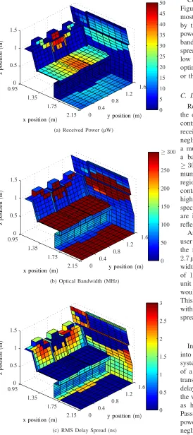
Firstly, considering the results for the rear passenger area
as shown in Figure 3, a maximum received power of 46µW
can be seen to be situated on the middle headrest with an
associated bandwidth of over ≥300MHz and a negligible
RMS delay spread. Similarly the left and right headrests can
receive a power between between 2.7µW and 25µW with
an associated bandwidth of at least 43MHz and a maximum
RMS delay spread of 2.3ns. The relatively high power and
bandwidth associated with these area may prove opportunisti-cally useful for any personal mobile equipment used near the passengers head, for example, wireless IR headphones.
Considering the lower section of the back seat, the region
can receive a power between 17µW and 39µW with with
an associated bandwidth of over≥300MHz and a negligible
RMS delay spread. Personal electronic devices such as mobile phones, laptops, hand-held computer consoles etc. would be adequately served in these locations. Advantageously, with this transmitter configuration the floor area is reasonable well illuminated with IR. Say for example one of the passengers drops their portable device, even under the seat edges, at
least 1µW, and up to a maximum of 17µW of IR can be
received with at least 47MHz of bandwidth and an RMS
delay spread maximum of2.0ns. This level of received power
and bandwidth is easily adequate for simple communication system overheads such as polling or hand-over routines.
On the interior door panels, the received power ranges from
between 3µW and 21µW with a minimum available
band-width of44MHz and maximum RMS delay spread of2.7ns.
This area would be extremely useful to place simple vehicular-passenger interface panels such as window, air-conditioning, heating or AV controllers.
B. Front Passenger and Driver Seats
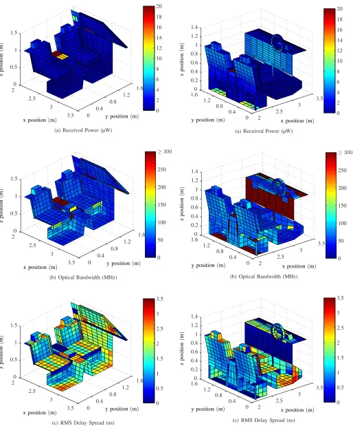
Moving onto the front seats as shown in Figure 4, due to the location of the transmitter being behind the front seats, the LOS component of received IR power is substantially reduced. The highest areas of received power can be found on the middle armrest between the driver and passenger with
a magnitude of up to 20µW, an associated bandwidth of
≥300MHz and a negligible RMS delay spread. This region
of the car is both useful to the rear passengers, potentially a place to leave portable equipment or house AV sources or consoles.
The other main area of interest, in this view of the SUV is around the window sills, where for example window or wing mirror controllers, heating or other rudimentary user interfaces may be located. Around the window sills, a reasonably high
x position(m) y position(m)
z
p
o
si
ti
o
n
(
m
)
0.95
1.35 1.75
2.15 0
5 10 15 20 25 30 35 40 45 50
0 0.4
0.8 1.2
1.6 0
0.5 1 1.5
(a) Received Power (µW)
x position(m) y position(m)
z
p
o
si
ti
o
n
(
m
)
0.95
1.35 1.75
2.15 0
50 100 150 200 250
≥300
0 0.4
0.8 1.2
1.6 0
0.5 1 1.5
(b) Optical Bandwidth (MHz)
x position(m) y position(m)
z
p
o
si
ti
o
n
(
m
)
0.95 1.35
1.75
2.15 0
0.5 1 1.5 2 2.5 3
0 0.4
0.8 1.2
1.6 0
0.5 1 1.5
(c) RMS Delay Spread (ns)
Fig. 3. Received power, optical bandwidth and RMS delay spread results for the rear passenger seats.
can be accounted for with an associated bandwidth of at least
50MHz and RMS delay spread of at most 0.5ns.
[image:6.595.56.330.136.752.2]Considering the the back of the front seats as shown in Figure 5, one area to note is the headrest area as this is the most likely deployment position for AV display screens used by the rear passengers. In this region the total IR received
power ranges between 3.6µW to 4.7µW with an associated
bandwidth of at least 48MHz and a maximal RMS delay
spread of 2.2ns. The power to these positions is a little
low by our requirement estimations and may indicate further optimisation of either the transmitter position or directionality, or the receiver position, orientation or FOV.
C. Dash Board and Steering Wheel
Referring to Figure 5, in the typically central location on the dashboard where an AV master unit and other vehicular
controls are located, a received power of around6µW can be
received with an associated bandwidth of ≥300MHz and a
negligible RMS delay spread. On the top of the dashboard,
a much lower power of up to 1.2µW can be obtained with
a bandwidth availability from 40MHz all the way up to
≥300MHz depending upon position with respective
maxi-mum RMS delay spread of 2.4ns. This is a very interesting
region of the vehicle interior, as in theory it should not contain much reflection from the glass window allowing for higher bandwidth and lower RMS delay spread. However, the specular nature of the reflections means that certain areas are illuminated more than others depending upon angles of reflection.
Another area of strong consideration for the placement of user vehicle interface devices is upon the steering wheel. On the front face and external rim, IR with power of between
2.7µW and 5.7µW can be detected with an available
band-width of at least 41MHz and maximal RMS delay spread
of 1.5ns. Behind the steering wheel, on the driver display
unit that typically houses the tachometer and speedometer etc. would be a highly suitable and relevant place for a receiver.
This region is subjected to a minimum IR power of 3.6µW
with at least45MHz of bandwidth and maximal RMS delay
spread of1.7ns.
IV. CONCLUSIONS
In conclusion, this paper has provided an initial analysis into the viability of implementing an OW communication system for intra-vehicle communications. Based upon the use
of a simple, linearly scalable 1W centrally located IR LED
transmitter, the results for received power, bandwidth and RMS
delay spread have been shown at over 3000 locations within
the vehicle. Of all the locations, several have been highlighted as having potentially advantageous channel characteristics. Passengers in the rear seats are exposed to signals with
powers of up to 49µW with bandwidths ≥300MHz and
x position(m) y position(m) z p o si ti o n ( m ) 2 2.5 3 3.5 0 2 4 6 8 10 12 14 16 18 20 0 0.4 0.8 1.2 1.6 0 0.5 1 1.5
(a) Received Power (µW)
x position(m) y position(m)
z p o si ti o n ( m ) 2 2.5 3 3.5 0 50 100 150 200 250 ≥300 0 0.4 0.8 1.2 1.6 0 0.5 1 1.5
(b) Optical Bandwidth (MHz)
x position(m) y position(m)
z p o si ti o n ( m ) 2 2.5 3 3.5 0 0.5 1 1.5 2 2.5 3 3.5 0 0.4 0.8 1.2 1.6 0 0.5 1 1.5
(c) RMS Delay Spread (ns)
Fig. 4. Received power, optical bandwidth and RMS delay spread results for the driver and front passenger seats.
x position(m) y position(m)
z p o si ti o n ( m ) 2 2.5 3 3.5 0 2 4 6 8 10 12 14 16 18 20 0 0.4 0.8 1.2 1.6 0 0.2 0.4 0.6 0.8 1 1.2 1.4
(a) Received Power (µW)
x position(m) y position(m)
z p o si ti o n ( m ) 2 2.5 3 3.5 0 50 100 150 200 250 ≥300 0 0.4 0.8 1.2 1.6 0 0.2 0.4 0.6 0.8 1 1.2 1.4
(b) Optical Bandwidth (MHz)
x position(m) y position(m)
z p o si ti o n ( m ) 2 2.5 3 3.5 0 0.5 1 1.5 2 2.5 3 3.5 0 0.4 0.8 1.2 1.6 0 0.2 0.4 0.6 0.8 1 1.2 1.4
[image:7.595.55.569.131.750.2](c) RMS Delay Spread (ns)
4.7µW with bandwidths of at least 48MHz which might be exploited for AV display screens embedded into the seats. In the front section of the vehicle, near the driver and passenger
doors, powers of up to 16µW with bandwidths of at least
50MHz and an RMS delay spread no more than 0.5ns can
be used for human-vehicle interfaces devices such as window, heating, or AV controllers. The dashboard area, in particular where an AV master unit may be housed, was exposed to
powers of around 6µW with bandwidths of ≥300MHz and
negligible RMS delay spread. This analysis, as the first of its type, will provide the foundations for a larger investigation into intra-vehicular communications including the optimisation of transmitter-receiver configurations and advances in the upper layer protocols than can exploit the specific channel characteristics shown to provide a high end user QoS. It should also be noted that although this paper and its results are based upon the use of an IR source, it might be possible in the future to extend the scope of the idea to include Visible Light LED transmitters supporting the newly released IEEE 802.17.7-2011 standard [22] supposing no safety concerns are raised about their use at night.
REFERENCES
[1] F. Bai and B. Krishnamachari, “Exploiting the wisdom of the crowd: Localized, distributed information-centric VANETs” IEEE Commun. Mag., vol. 48, no. 5, pp. 138 –146, 2010.
[2] K. Dar, M. Bakhouya, J. Gaber, M. Wack, and P. Lorenz, “Wireless communication technologies for ITS applications,” IEEE Commun. Mag., vol. 48, no. 5, pp. 156 –162, 2010.
[3] D. C. O’Brien, M. Katz, P. Wang, K. Kalliojarvi, S. Arnon, M. Mat-sumoto, R. J. Green, and S. Jivkova, “Short range optical wireless communications,”Wireless World Research Forum, 2005.
[4] R. J. Green, H. Joshi, M. D. Higgins, and M. S. Leeson, “Recent developments in indoor optical wireless systems,”IET Commun., vol. 2, no. 1, pp. 3 –10, 2008.
[5] R. J. Green, “Optical wireless with application in automotives,” inProc. IEEE Int. Conf. Transparent Optical Netw. (ICTON),2010, pp We.C3.2. [6] M. D. Higgins, R. J. Green, and M. S. Leeson, “A genetic algorithm method for optical wireless channel control,”IEEE J. Lightwave Tech., vol. 27, no. 6, pp. 760 –772, 2009.
[7] M. D. Higgins, R. J. Green, M. S. Leeson, and E. L. Hines, “Multi-user indoor optical wireless communication system channel control using a genetic algorithm,”IET Commun., vol. 5, no. 7, pp. 937 –944, 2011. [8] B. T. Phong, “Illumination for computer generated pictures,”Commun
ACM, vol. 18, no. 6, pp. 311–317, 1975.
[9] S. R. Perez, R. P. Jimenez, F. J. L´opez-Hern´andez, O. B. G. Hernandez, and A. J. A. Alfonso, “Reflection model for calculation of the impulse response on IR-wireless indoor channels using ray-tracing algorithm,” Microwave. Opt. Technol. Lett., vol. 32, no. 4, pp. 296–300, 2002. [10] C. R. Lomba, R. T. Valadas, and A. M. de Oliveira Duarte,
“Experimen-tal characterisation and modelling of the reflection of infrared signals on indoor surfaces,”IEE Proc. Optoelectron., vol. 145, pp. 191–197, 1998. [11] K. Dana, B. Van-Ginneken, S. Nayar, and J. Koenderink, “Reflectance and Texture of Real World Surfaces,”ACM Transactions on Graphics (TOG), vol. 18, no. 1, pp. 1–34, 1999.
[12] M. Oren and S. Nayar, “Seeing Beyond Lambert´s Law,” in Proc. European Conference on Computer Vision (ECCV), vol. B, May 1994, pp. 269–280.
[13] D. Salomon, Curves and Surfaces for Computer Graphics, Springer-Verlag, 2006.
[14] J. R. Barry, J. M. Kahn, W. J. Krause, E. A. Lee, and D. G. Messer-schmitt, “Simulation of multipath impulse response for indoor wireless optical channels,”IEEE J. Sel. Areas Commun., vol. 11, no. 3, pp. 367– 379, 1993.
[15] J. M. Kahn, W. J. Krause, and J. B. Carruthers, “Experimental characteri-zation of non-directed indoor infrared channels,”IEEE Trans. Commun., vol. 43, no. 234, pp. 1613 –1623, 1995.
[16] BS EN60828:1994: Safety of Laser Products, Equipment Classification, Requirements and User’s Guide Std.
[17] A. C. Boucouvalas, “IEC 825-1 eye safety classification of some consumer electronic products,”IEE Seminar Digests, vol. 1996, no. 32, pp. 13/1–13/6, 1996.
[18] J. B. Carruthers and P. Kannan, “Iterative site-based modelling for wireless infrared channels,” IEEE Trans. Antennas Propag., vol. 50, no. 5, pp. 759–765, 2002.
[19] A. S. Glassner,An introduction to ray tracing, London: Academic Press, 1989.
[20] A. Lagae and P. Dutr, “An efficient ray-quadrilateral intersection test,” J. Graphics, GPU Game Tools, vol. 10, no. 4, pp. 23–32, 2005. [21] M. R. Pakravan and M. Kavehrad, “Indoor wireless infrared channel
characterization by measurements,”IEEE Trans. Veh. Technol., vol. 50, no. 4, pp. 1053–1073, 2001.
[22] “IEEE standard for local and metropolitan area networks–part 15.7: Short-range wireless optical communication using visible light,” IEEE Std 802.15.7-2011, pp. 1 –309, June 2011.
Matthew D. Higginsreceived his MEng in Electronic and Communications Engineering and PhD in Engineering from the School of Engineering at the University of Warwick in 2005 and 2009 respectively. Remaining at the University of Warwick, he then progressed through several Research Fellow positions with leading defence and telecommunications companies before taking up his current position as a Senior Teaching Fellow in Communi-cations. His major research interests are the modelling of optical propagation characteristics in underwater, indoor and atmospheric conditions and how the channel can affect communications systems. Dr. Higgins is a Member of both the IEEE and IET.
Roger J. Green holds a Ph.D. in Video Communications from Bradford University and a D.Sc. in Photonic Communications, Systems and Devices from the University of Warwick. As the Professor of Electronic Commu-nication Systems, he is the current head of the CommuCommu-nications Systems Laboratory (ComSysLab) at the University of Warwick. His specialization is Photonic Communications, to include optical wireless and optical fibre communications, together with ongoing research into 3D optoelectronics. He is a Senior Member of the IEEE, a Fellow of the IET (UK) and of the Institute of Physics (UK). With a research team of around 12 Ph.D. students, he has 7 patents and over 230 published research papers. He has held the position of Head of the Division of Electrical and Electronic Engineering at Warwick for a 5 year term, is a member of the Engineering Professors Council (EPC/PHEE Division), and hosted the EPC Congress in 2008. He is a current member of the EPSRC College in the UK. He contributes regularly to international conferences and journals, and is a member of the ICTON (IEEE) conference committee.