A Virtual Synchronous Machine to Support Dynamic
Frequency Control in a Mini-Grid That Operates in
Frequency Droop Mode
Miguel Torres, Luiz A. C. Lopes
Department of Electrical and Computer Engineering, Concordia University, Montreal, Canada Email: [email protected], [email protected]
Received February 28,2013; revised March 30, 2013; accepted April 12, 2013
Copyright © 2013 Miguel Torres, Luiz A. C. Lopes. This is an open access article distributed under the Creative Commons Attribu-tion License, which permits unrestricted use, distribuAttribu-tion, and reproducAttribu-tion in any medium, provided the original work is properly cited.
ABSTRACT
This paper addresses the problem of dynamic frequency control in a diesel-based mini-grid. It is shown that a virtual synchronous machine (VSM) can support dynamic frequency control by adding virtual inertia and damping to the sys-tem. However, it is found that the typical formulation of damping power does not work properly when the grid forming gen-set operates in droop mode because of the unknown stabilization value of the grid frequency. As a solution to this problem, an estimator for the stabilization frequency that works in conjunction with the damping function of the VSM is proposed. Theoretical and experimental results provide evidence of a satisfactory performance of the proposed VSM with estimator for different values of the gen-set droop factor. The estimated stabilization frequency converges in ap-proximately 2 s and the maximum frequency deviation during the transient is reduced in 34%, on average.
Keywords: Frequency Control; Mini-Grid; Inverter; Virtual Synchronous Machine
1. Introduction
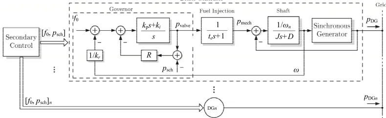
Frequency stability is of more concern in “small” power systems, such as mini-grids, where any individual gen-erator in-feed represents a substantial portion of the total demand. The initial rate of change of frequency is typi-cally higher than in large interconnected power systems [1,2] and a lower value of frequency can be reached in a shorter time (for a power increase). In diesel-based mini-grids, frequency is primarily controlled by the grid-forming diesel units. Figure 1 shows the schematic
of a supervisory controller of a diesel power plant. Each gen-set presents a primary controller, implemented in the governor, whose main function is to adjust the speed of the gen-set. Since most gen-sets employ a synchronous generator, the governor indirectly controls the frequency of the generated voltage. If the frequency is to be kept constant, an isochronous governor can be used. However, if multiple gen-sets are to operate in parallel, it is more convenient to use a droop based governor where the speed and frequency of a gen-set decrease as its output
f pDG
pDGn p
0
pvalve mech
DGn psch
[f0, psch]n [f0, psch]
R
ω
1/kr
s tes+1 Js+D
1/ωn 1
[image:1.595.100.495.595.716.2]kps+ki
Figure 1. Diesel generator control.
power increases. Besides, operation with variable fre-quency can be advantageous because it naturally conveys the information of shortage (low frequency) or excess (high frequency) of active power in the mini-grid. This would allow controllable loads, energy storage systems (ESS) and power sources dispersed in the mini-grid to adjust their active power levels accordingly, without the need for a dedicated communication channel [3-5]. The frequency droop characteristic of a gen-set can be re- presented in steady-state by:
0
1
f f
R
p
p
DG sch
p p (1)
where DG is the actual power supplied by the gen-set,
f is the grid frequency, sch and f0 are input values
that can be set by the secondary control, and is the droop factor usually selected so that decreases by about 3% - 5% as varies from no-load to full-load. In the isochronous mode, R is set to 0, meaning that the grid frequency will not change regardless of the output power level.
R
p
Frequency stability issues usually appear up to a few seconds following variations in the power demanded from the diesel power plant. They are addressed primar-ily by the primary frequency control which should make sure that the frequency excursions remain within accept-able values. The secondary control, adjusts the values of
0 and/or sch to bring the frequency of the mini-grid
back to a desired value after the disturbance or to adjust the amount of power provided by each parallel gen-set so as to keep them loaded at safe and more economical lev-els as computed by an economic dispatch algorithm [5]. However, due to a slower speed of response, the secon-dary control cannot make a meaningful contribution re-garding frequency stability. The supervisory control sys-tem of a diesel-based mini-grid can be made very sophis-ticated, with multiple hierarchical control levels, em-ploying modern information and communication tech-nology [6]. This paper however focuses on frequency stability issues which can be appropriately studied con-sidering only the primary control of the gen-sets.
f
One important element in the variation of the grid fre-quency after variations in demand and before the primary controls reactions, is the amount of kinetic energy stored in the rotating masses of the diesel power plant, which tends to reduce the initial frequency rate of change. When a diesel-based mini-grid operates with a reduced number of gen-sets or a high penetration of inertia-less distributed power sources, frequency stability can dete-riorate [7]. In this regard, virtual synchronous machines (VSM), which can be defined as inverters that emulate a synchronous generator (SG) or a desired characteristic of it, have been proposed as a solution to address stability
issues in power systems with large fraction of inverter- connected distributed generators [8-12]. Most of the re- ported works on VSMs have focused only on the emula- tion of inertial response. This paper, however, presents the case of a VSM that also includes the injection of damping power.
The paper is organized as follows. In Section 2 the concept of virtual synchronous machine is introduced and it is shown that when the mini-grid operates in fre-quency droop mode the typical formulation of damping power does not work properly because of the unknown stabilization frequency of the grid. In order to address this problem, an estimator of the stabilization frequency of the grid is proposed in Section 3 and evaluated theo-retically. Then, in Section 4 the performance of the damping function of the VSM in conjunction with the estimator is evaluated experimentally. Finally, the con-clusions are presented in Section 5.
2. Concept of Virtual Synchronous Machine
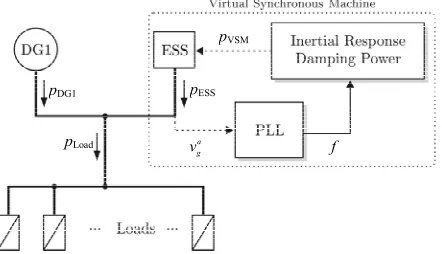
A VSM basically entails the control of the grid-interface converter of a distributed generator or ESS in order to emulate a synchronous generator (SG) or a desired char-acteristic of it. Figure 2 illustrates the concept of the
VSM considered in this work.
The grid frequency (f) is locally measured at the point where the ESS is connected and then, based on the measured frequency, the output power of the VSM
p
VSM is calculated, which turns out to be the reference
for the output active power of the ESS
ESS . Tosup-port dynamic frequency control, the strategy involves emulating two characteristics os a SG that are present only during the transient: the inertial response
p
p
VSM i
and the damping power
pVSM d
p p, with the total output p
power of the VSM being VSM VSM i VSM d . The inertial response emulates the power that is natu-rally released or absorbed by a conventional rotating generator as the power demand varies and before its governor reacts. The emulation of inertial response typi-cally entails the generation of a power reference that is
pVSM
a g v
pDG1 pESS
[image:2.595.314.535.589.716.2]pLoad f
inversely proportional to the first time-derivative of the grid frequency [7,13]. Therefore, when the frequency of the grid starts to decay (a negative derivative), the power converter which is in charge of emulating the inertial response starts to inject power to the grid until the fre-quency reaches its minimum (when the first derivative is zero), then the frequency starts to increase (a positive derivative) and the converter starts to absorb power. This process will continue until steady-state is achieved. The output power of the VSM due to the inertial response can be defined as:
t(s)
vi r2 dd
VSM i
f
p k k f
t
k
(2)
where vi represents the virtual inertia, kr4π np is
a constant that relates the electrical frequency with the rotational speed of the VSM, and np is the number of
poles of the VSM. The main effect of adding virtual iner-tia to the system is that the rate of change of the fre-quency decreases. However, given that the parameters of the governor(s) remain unchanged and considering that they have been tuned for a specific value of inertia, a side effect of adding virtual inertia is that the frequency os-cillates for a longer time after a power disturbance.
The injection of damping power is another function that can be performed by the VSM that helps to stabilize frequency. It is typically calculated as the difference be-tween a reference frequency and the actual frequency of the system as follows:
k f fk2
f
k
vd VSM d
p k (3) where vd is the damping coefficient and f is the
[image:3.595.313.535.82.297.2]reference frequency that the system is supposed to reach in steady-state. Any deviation from the reference fre-quency produces a power that attempts to bring back the grid frequency to the reference, attenuating the amplitude of the oscillations [7,14]. One of the main assumptions in the calculation of the damping power is that the reference frequency, which should be the nominal frequency of the grid, is known. This assumption usually holds true in the case of stiff power systems or mini-grids that operate in isochronous mode, where the value of frequency in steady-state is expected to be fixed (e.g. 60 Hz). How-ever, this might not be the case of mini-grids that operate in droop mode, where the frequency of the grid changes with the load level.
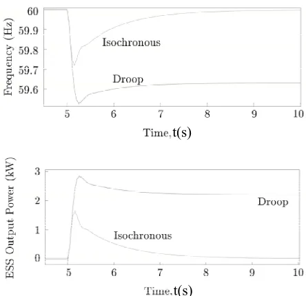
Figure 3 compares the performance of the VSM vi vd in two scenarios: when the gen-set
operates in isochronous mode at a nominal frequency of 60 Hz and when the gen-set operates in droop mode with droop coefficient Hz/kW (6% droop).
k 0,k 10
= 0.12 R
5
In both cases the gen-set starts in 60 Hz with no load and the load increases in 5 kW at t s. Also, the nominal frequency of 60 Hz is used in both cases as the
t(s)
60
f
Figure 3. Simulation of the VSM with the gen-set in droop mode. (a) Frequency waveforms; (b) ESS output active power.
stabilization frequency to compute the damping power (3) (as discussed before, it is assumed that the actual stabili-zation frequency during droop operation is not available for the VSM because it is an internal variable of the gen-set governor). Figure 3(a) shows the frequency
waveforms and Figure 3(b) shows the output active
power of the ESS. It can be seen that in the case of isochronous operation the output power of the ESS goes to zero as the grid frequency returns to 60 Hz after the transient. In the case of droop operation, due to the as-sumption Hz a miscalculation of the damping term occurs, which produces an output power of 2.2 kW for the ESS in steady-state. This continuous output power is considered an undesired behavior of the VSM, whose purpose is to assist frequency control only during the transient. Therefore, in order to inject damping power under frequency droop mode, the reference frequency
f in (3) should follow the stabilization frequency ofthe grid instead of being a fixed value. In the next section, an estimator of the stabilization frequency is proposed as a solution to provide the reference frequency for the damping function of the VSM.
3. Estimation of the Stabilization Frequency
The proposed estimator consists in a proportional integral (PI) controller with droop factor, which resembles the structure of the speed governor shown in Figure 1. The
block diagram of the estimator is depicted in Figure 4,
where f is the estimated stabilization frequency, is the estimated control error, and 0 p i
e
, , ,
f
p 0.5p
e k k
e
p p
e k k
[image:4.595.57.291.82.184.2]
Figure 4. Open-loop estimator. t
1.5
p p
e k k
simple, it has been defined as an open-loop estimator, which means that its performance will depends on how close its parameters are to the actual parameters of the governor. For this reason, a sensitivity analysis is con-ducted to evaluate the performance of the estimator for different values of its parameters.
Sensitivity Analysis
The sensitivity analysis entails disturbing the system with a step-like load increase of 5 kW and plotting the result-ing estimated frequency control error
e0.12
for different values of the estimator parameters. The possible range of variation for each parameter is defined as [0.5, 1.5] pu of its ideal value (the genset actual parameter). The gen-set operates in droop mode ( Hz/kW), it starts with a load of 20 kW and it is disturbed with a step-like load increase of 5 kW at s. The VSM is not connected to the grid. The results for the variation of parameter 0
R
5
t
f
are not shown because it was found that its value acted as an initial bias for which was rapidly eliminated by the integrator, therefore affecting only the start-up of the estimator.
[image:4.595.310.536.85.198.2] [image:4.595.310.535.244.355.2]e
Figure 5 shows the results for the variation of the
pro-portional gain
kp while the other parameters remainconstant and equal to their ideal values. In the same way,
Figures 6 and 7 show the results for the integral gain and
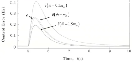
the droop factor, respectively. In these three figures, the ideal control error (internal variable of the gen-set gov-ernor) is shown in green solid line. In order to evaluate the impact of each parameter on the estimation, the mean absolute error is calculated taking the case when
,
p p i i and (which is the best
perform-ance that the estimator can achieve) as the reference curve. The results are presented in Table 1. It can be
observed that the estimation errors are greater when the estimator parameters are, within the range of analysis [0.5, 1.5] pu, below their ideal values and the maximum error is 0.103 Hz which corresponds to a 0.17% of the nominal frequency. The parameter with the highest im-pact on increasing the estimation error is the droop factor
whereas the parameter with the lowest impact is the integral gain
k k
R k
k
R R
i
After evaluating the variation of each parameter inde-
k .
Figure 5. Influence of the proportional gain kp on the
estimated control error.
i 0.5i
e k k
e
i i
e k k
t 1.5
i i
e k k
Figure 6. Influence of the integral gain ki on the esti-
mated control error.
0.5 dr
e m m
dr
e m m e
t
1.5 dr
e m m
RFigure 7. Influence of the droop factor on the esti-
[image:4.595.313.534.406.511.2]mated control error.
Table 1. Mean absolute errors *(Hz) in estimations of Fig- ures 5-7.
Parameter\pu value 0.5 1.5
p
k 0.058 0.035
i
k 0.060 0.022
R 0.103 0.035
*Calculated as 1
N ref
n n
n
x x
refn , where
N
1 x is the reference value and
is the number of points of the analysis.
N
[image:4.595.308.540.578.685.2] for both cases.
the range of interest [0.5, 1.5] pu (using the MATLAB command “ ”) and then used to define the parameters of the estimator as:
rand 3,1
, 1.3
0.5
0.8
p p i i
and . Figure 8 shows the estimated control
error with a mean absolute error of 0.024 Hz, which cor-responds to a 0.04 % of the nominal frequency. The rela-tively low value of this error along with the ones pre-sented in Table 1 demonstrate a satisfactory performance
of the estimator.
k k k k
R 0.9
R
4. Experimental Results
A schematic of the experimental setup is depicted in
Figure 9. An inverter-based emulator [15] is used to
represent the diesel generator and the loads are repre-sented by a bank of resistors. The VSM is implemented with a second inverter which is controlled in decoupled power mode [16]. Since only the damping function is evaluated, the reference for the reactive power is set to zero and the reference for the active power is given by (3).
In the first test, the gen-set operates with a droop fac-tor of 6% and the estimafac-tor is tuned with the same pa-rameters of the gen-set. The response of the system to a step-like load increase is first obtained with the VSM disconnected from the grid. Then, the VSM is connected to the grid and the load increase is repeated. Figure 10
shows the frequency of the system f and the estimator
e
t
e
Figure 8. Estimated control error for random variation in parameters.
k k R p, ,i
abc g
v
abc ESS
i
pVSM
f
abc Load
i
abc DG
i
abc ESS
i
abc g
v
e
R1···R4
Figure 9. Experimental setup of the VSM with stabilization frequency estimator.
signals e and f
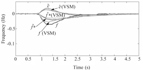
A second test is performed to evaluate the perform-ance of the estimator when the droop factor of the gen-set is reduced to 3% while the parameters of the es-timator remain unchanged (which was originally tuned considering a 6% droop in the gen-set). As in the previ-ous test, a step-like load increase is produced with the VSM connected and disconnected from the system.
Figure 11 shows the frequency of the system f and the
estimator signals and f for both cases.
Finally, the droop factor of the gen-set is changed to 0 % while the parameters of the estimator remain un-changed in its original values. As in the previous test, a step-like load increase is produced with the VSM con-nected and disconcon-nected from the system. Figure 12
shows the frequency of the system f and the estimator signals e and f for both cases.
These experimental results support the results obtained in the sensitivity analysis, showing a satisfactory per-formance of the estimator when the gen-set droop factor is reduced from 6% to 3% and even to 0% (isochronous mode). In all three cases, the estimated control error
econverged to zero in approximately 2 s and the VSM was able to effectively reduce the frequency nadir, on average, in 34%.
5. Conclusion
This paper addressed the problem of dynamic frequency
Figure 10. Load increase with gen-set operating with 6% frequency droop.
Figure 12. Load increase with gen-set operating in iso- chronous mode.
control in a diesel-based mini-grid. It was shown that a VSM can support dynamic frequency control (enhance frequency stability) by adding virtual inertia and damp-ing to the system. However, it was also shown that the typical formulation of damping power does not work properly when the gen-set operates in droop mode be-cause of the unknown stabilization frequency of the grid. As a solution, an estimator for the stabilization frequency that works in conjunction with the damping function of the VSM was proposed. Theoretical and experimental results showed a satisfactory performance of the pro-posed VSM with estimator in reducing the maximum frequency deviation during the transient for different values of the gen-set droop factor.
REFERENCES
[1] P. Kundur, J. Paserba, V. Ajjarapu, G. Andersson, A. Bose, C. Canizares, N. Hatziargyriou, D. Hill, A. Stank- ovic, C. Taylor, T. Van Cutsem and V. Vittal, “Definition and Classification of Power System Stability IEEE/CI- GRE Joint Task Force on Stability Terms and Defini- tions,” IEEE Transactions on Power Systems, Vol. 19, No. 3, 2004, pp. 1387-1401.
doi:10.1109/TPWRS.2004.825981
[2] IEEE Std 1159-2009 (Revision of IEEE Std 1159-1995) Recommended Practice for Monitoring Electric Power Quality, IEEE Std., 2009.
[3] R. Tonkoski and L. A. C. Lopes, “Enhanced Part Load Operation of Hybrid Mini-Grids with High Penetration of Photovoltaics,” 3rd Brazilian Conference on Solar En- ergy, Belém, 21-24 September 2010.
[4] K. Elamari and L. A. C. Lopes, “Frequency Based Con- trol of Electric Water Heaters in Small PV-Diesel Hybrid Mini-Grids,” 25th Canadian Conference on Electrical and Computer Engineering, Montreal, 29 April-2 May 2012, pp. 1-4.
[5] L. A. C. Lopes and M. Dalal-Bachi, “Economic Dispatch
and Demand Side Management via Frequency Control in PV-Diesel Hybrid Mini-Grids,” 6th European Conference on PV-Hybrid and Mini-Grids, Chambery, 26-27 April 2012, pp. 266-273.
[6] F. Katiraei, R. Iravani, N. Hatziargyriou and A. Dimeas, “Microgrids Management,” IEEE Power and Energy Ma- gazine, Vol. 6, No. 3, 2008, pp. 54-65.
doi:10.1109/MPE.2008.918702
[7] J. Morren, S. de Haan and J. Ferreira, “Contribution of DG Units to Primary Frequency Control,” 2005 Interna- tional Conference on Future Power Systems, Amsterdam, 18 November 2005, p. 6.
[8] S. De Haan, R. Van Wesenbeeck and K. Visscher, “VSG Control Algorithms: Present Ideas,” 2008.
http://www.vsync.eu. Project VSYNC
[9] K. Visscher and S. De Haan, “Virtual Synchronous Ma- chines (VSGs) for Frequency Stabilisation in Future Grids with a Significant Share of Decentralized Genera- tion,” CIRED Seminar SmartGrids for Distribution, Frank- furt, 23-24 June 2008, pp. 1-4.
[10] Q. C. Zhong and G. Weiss, “Static Synchronous Genera- tors for Distributed Generation and Renewable Energy,” Power Systems Conference and Exposition, Seattle, 15-18 March 2009, pp. 1-6.
[11] M. Van Wesenbeeck, S. de Haan, P. Varela and K. Viss- cher, “Grid Tied Converter with Virtual Kinetic Storage,” PowerTech, 2009 IEEE Bucharest, Bucharest, 28 June-2 July 2009, pp. 1-7.
[12] Q. C. Zhong and G. Weiss, “Synchronverters: Inverters That Mimic Synchronous Generators,” IEEE Transac- tions on Industrial Electronics, Vol. 58, No. 4, 2011, pp. 1259-1267. doi:10.1109/TIE.2010.2048839
[13] J. Morren, S. de Haan, W. Kling and J. Ferreira, “Wind Turbines Emulating Inertia and Supporting Primary Fre- quency Control,” IEEE Transactions on Power Systems, Vol. 21, No. 1, 2006, pp. 433-434.
doi:10.1109/TPWRS.2005.861956
[14] X. Yingcheng and T. Nengling, “Review of Contribution to Frequency Control through Variable Speed Wind Tur- bine,” Renewable Energy, Vol. 36, No. 6, 2011, pp. 1671- 1677.
http://www.sciencedirect.com/science/article/pii/S096014 8110005112 =0pt
[15] M. Torres and L. A. C. Lopes, “Inverter-Based Virtual Diesel Generator for Laboratory-Scale Applications,” 36th Annual Conference on IEEE Industrial Electronics Society, Glendale, 7-10 November 2010, pp. 532-537. [16] T. S. Lee, “Input-Output Linearization and Zero-Dy-
namics Control of Three-Phase ac/dc Voltage-Source Converters,” IEEE Transactions on Power Electronics, Vol. 18, No. 1, 2003, pp. 11-22.
Appendix
Gen-set model parameters: nominal power = 30 kW, nominal frequency = 60 Hz, k k
Hz/kW (6% droop), . 9.425
π r
k p , i 14.137,
0.12
R