Hack Attacks Revealed
This netLibrary eBook does not include the ancillary media that was packaged with the original printed version of the book.
Publisher: Robert Ipsen Editor: Carol A. Long
Assistant Editor: Adaobi Obi
Managing Editor: Micheline Frederick New Media Editor: Brian Snapp
Text Design & Composition: Thomark Design
Designations used by companies to distinguish their products are often claimed as trademarks. In all instances where John Wiley & Sons, Inc., is aware of a claim, the product names appear in initial capital or ALL CAPITAL LETTERS. Readers, however, should contact the appropriate companies for more complete information regarding trademarks and registration.
Copyright © 2001 by John Chirillo. All rights reserved. Published by John Wiley & Sons, Inc.
No part of this publication may be reproduced, stored in a retrieval system or transmitted in any form or by any means, electronic, mechanical, photocopying, recording, scanning or otherwise, except as permitted under Sections 107 or 108 of the 1976 United States Copyright Act, without either the prior written permission of the Publisher, or authorization through payment of the appropriate per-copy fee to the Copyright Clearance Center, 222 Rosewood Drive, Danvers, MA 01923, (978) 750-8400, fax (978) 750-4744. Requests to the Publisher for permission should be addressed to the Permissions Department, John Wiley & Sons, Inc., 605 Third Avenue, New York, NY 10158-0012, (212) 850-6011, fax (212) 850-6008, E-Mail: PERMREQ @ WILEY.COM.
This publication is designed to provide accurate and authoritative information in regard to the subject matter covered. It is sold with the understanding that the publisher is not engaged in professional services. If professional advice or other expert assistance is required, the services of a competent professional person should be sought.
This title is also available in print as ISBN 0-471-41624-X
Contents
Acknowledgments xi
A Note to the Reader xii
Introduction xiii
Part I: In the Beginning
1
Chapter 1 Understanding Communication Protocols 3
A Brief History of the Internet 3
Internet Protocol 5
IP Datagrams, Encapsulation, Size, and Fragmentation
8
IP Addresses, Classes, Subnet Masks 10
Subnetting, VLSM, and Unraveling IP the Easy Way
11 ARP/RARP Engineering: Introduction to Physical
Hardware Address Mapping
22 ARP Encapsulation and Header Formatting 23
RARP Transactions, Encapsulation 24
RARP Service 25
Transmission Control Protocol 25
Sequencing and Windowing 26
TCP Packet Format and Header Snapshots 26
Ports, Endpoints, Connection Establishment 28
User Datagram Protocol 30
UDP Formatting, Encapsulation, and Header Snapshots
30 Multiplexing, Demultiplexing, and Port Connections 31
Internet Control Message Protocol 32
ICMP Format, Encapsulation, and Delivery 32
ICMP Messages, Subnet Mask Retrieval 33
ICMP Header Snapshots 36
Moving Forward 36
Chapter 2 NetWare and NetBIOS Technology 37
NetWare: Introduction 37
Internetwork Packet Exchange 37
Sequenced Packet Exchange 44
SPX Format, Header Snapshots 44
Connection Management, Session Termination 45
Watchdog Algorithm 45
NetBIOS Technology: Introduction 47
Naming Convention, Header Snapshots 48
General, Naming, Session, and Datagram Services 48
NetBEUI: Introduction 50
NetBIOS Relationship 50
Windows and Timers 50
Conclusion 51
Part II: Putting It All Together 53
Chapter 3 Understanding Communication Mediums 55
Ethernet Technology 55
Carrier Transmissions 56
Ethernet Design, Cabling, Adapters 57
Hardware Addresses, Frame Formats 60
Token Ring Technology 60
Operation 62
Token Ring Design, Cabling 62
Prioritization 62
Fault Management 63
Addresses, Frame Format 63
Fiber Distributed Data Interface Technology 64
Operation 65
FDDI Design, Cabling 66
Frame Format 66
Analog Technology 67
Problem Areas and Remedies 67
System Registry 69
Integrated Services Digital Network Technology 71
ISDN Devices 71
ISDN Service Types 72
ISDN versus Analog 72
Digital Subscriber Line 73
Point-to-Point Technology 74
PPP Operation 74
Frame Structure 75
Frame Relay Technology 76
Operation, Devices, Data-Link Connection Identifiers, and Virtual Circuits
Frame Relay Frame Format 79
Looking Ahead 79
Part III: Uncovering Vulnerabilities 81
Intuitive Intermission A Little Terminology 83
Who Are Hackers,
Crackers, Phreaks, and Cyberpunks?
83
What Is Hacking? 84
Profiling the Hacker 87
Security Levels 88
Security Class C1: Test
Condition Generation
88
Security Class C2: Test
Condition Generation
89
Security Class B1: Test
Condition Generation
90
Security Class B2: Test
Condition Generation
91
Kickoff 92
Chapter 4 Well-Known Ports and
Their Services
93
A Review of Ports 93
TCP and UDP Ports 94
Well-Known Port
Vulnerabilities
94
Unidentified Ports and
Services
109
What’s Next 147
Chapter 5 Discovery and Scanning
Techniques
149
Discovery 149
Whois Domain Search
Query
151
Host PING Query 153
Internet Web Search
Query
156
Social Engineering Query 156
Site Scans 157
Scanning Techniques 158
Scanner Packages 159
Sample Scan 173
Part IV: Hacking Security Holes
181
Intuitive Intermission A Hacker’s Genesis 183
Chapter 6 The Hacker’s Technology
Handbook
189
Networking Concepts 189
Open Systems
Interconnection Model
189
Cable Types and Speeds
versus Distances
191
Decimal, Binary, and Hex
Conversions
192
Protocol Performance
Functions
204
Networking Technologies 205
Media Access Control
Addressing and Vendor Codes
205
Ethernet 206
Token Ring 215
Token Ring and Source
Route Bridging
216
Token Ring and Source
Route Translational Bridging
221
Fiber Distributed Data
Interface
223
Routing Protocols 225
Distance Vector versus
Link State Routing Protocols
226
Routing Information
Protocol
228
Interior Gateway Routing
Protocol
229
Appletalk Routing Table
Maintenance Protocol
230
Open Shortest Path First
Protocol
230
Important Commands 231
Append 232
Assign 233
Attrib 234
Break 235
Chcp 236
Chdir (CD) 236
Chkdsk 237
Cls 238
Command 238
Comp 239
Copy 239
Ctty 240
Date 241
Del(Erase) 241
Dir 242
Diskcomp 243
Diskcopy 243
Exe2bin 244
Exit 244
Fastopen 245
Fc 245
Fdisk 247
Find 247
Format 248
Graftabl 249
Graphics 249
Join 250
Keyb 251
Label 252
Mkdir (MD) 253
Mode 253
More 257
Nlsfunc 257
Path 257
Print 258
Prompt 259
Recover 260
Ren (Rename) 261
Replace 261
Restore 262
Select 263
Set 264
Share 265
Sort 265
Subst 266
Sys 267
Time 267
Tree 268
Type 268
Ver 269
Verify 269
Vol 269
Xcopy 270
Looking Ahead 271
Chapter 7 Hacker Coding
Fundamentals
273
The C Programming
Language
273
Versions of C 274
Classifying the C
Language
275
Structure of C 276
Comments 277
Libraries 277
C Compilation 278
Data Types 279
Operators 283
Functions 285
C Preprocessor Commands 290 Program Control Statements 293
Input and Output 297
Pointers 301
Structures 304
File I/O 311
Strings 321
Text Handling 328
Debugging 338
Float Errors 339
Error Handling 339
Casting 343
Prototyping 344
Pointers to Functions 345
Sizeof 347
Interrupts 347
Signal 350
Dynamic Memory
Allocation
351
Atexit 354
Increasing Speed 355
Directory Searching 356
Accessing Expanded Memory 359 Accessing Extended Memory 363
TSR Programming 373
Conclusion 405
Chapter 8 Port, Socket, and Service
Vulnerability Penetrations 407
Example Case Synopsis 407
Backdoor Kits 408
Implementing a Backdoor
Kit
411
Common Backdoor
Methods in Use
411
Packet Filters 412
Stateful Filters 417
Proxies and Application
Gateways
422
Flooding 423
Log Bashing 434
Covering Online Tracks 434
Covering Keylogging
Trails
436
Mail Bombing,
Spamming, and Spoofing 447
Password Cracking 449
Cracking
Remote Control 455
Step 1: Do a Little
Research
456
Step 2: Send the Friendly
E-Message
456
Step 3: Claim Another
Victim
457
Sniffing 459
Spoofing IP and DNS 470
Case Study 471
Trojan Infection 480
Viral Infection 489
Wardialing 490
Web Page Hacking 492
Step 1: Conduct a Little
Research
494
Step 2: Detail Discovery
Information
495
Step 3: Launch the Initial
Attack
498
Step 4: Widen the Crack 499
Step 5: Perform the Web
Hack
499
Part V: Vulnerability Hacking
Secrets
503
Intuitive Intermission A Hacker’s Vocation 505
Chapter 9 Gateways and Routers and Internet
Server Daemons
507
Gateways and Routers 507
3Com 508
Ascend/Lucent 516
Cabletron/Enterasys 524
Cisco 533
Intel 541
Nortel/Bay 549
Internet Server Daemons 554
Apache HTTP 555
Lotus Domino 556
Netscape Enterprise Server 560
Novell Web Server 564
O’Reilly WebSite Professional 567
Conclusion 572
Chapter 10 Operating Systems 573
UNIX 574
AIX 576
BSD 586
HP/UX 602
IRIX 612
Linux 616
Macintosh 645
Microsoft Windows 649
Novell NetWare 668
OS/2 678
SCO 694
Solaris 697
Conclusion 700
Chapter 11 Proxies and Firewalls 701
Internetworking Gateways 701
BorderWare 701
FireWall-1 706
Gauntlet 710
NetScreen 714
PIX 719
Raptor 727
WinGate 730
Conclusion 736
Part VI: The Hacker’s Toolbox 737
Intuitive Intermission The Evolution of a Hacker 739 Chapter 12 TigerSuite: The Complete Internetworking
Security Toolbox
749
Tiger Terminology 749
Introduction to TigerSuite 754
Installation 754
Program Modules 758
System Status Modules 759
TigerBox Scanners 772
TigerBox Penetrators 775
TigerBox Simulators 775
Sample Real-World Hacking Analysis 777
Step 1: Target Research 778
Step 2: Discovery 782
Step 3: Social Engineering 784
Step 4: Hack Attacks 786
Conclusion 786
Appendix A IP Reference Table and Subnetting Charts 789
Appendix B Well-Known Ports and Services 793
Appendix C All-Inclusive Ports and Services 799
Appendix D Detrimental Ports and Services 839
Appendix E What’s on the CD 845
Tiger Tools 2000 846
TigerSuite (see Chapter 12) 846
Chapter 5 847
jakal 847
nmap 847
SAFEsuite 848
SATAN 848
Chapter 8 848
Backdoor Kits 848
Flooders 848
Log Bashers 848
Mail Bombers and Spammers 849
Password Crackers 849
Remote Controllers 852
Sniffers 853
Spoofers 855
Trojan Infectors 855
Viral Kits 856
Wardialers 856
Chapters 9, 10, and 11 857
Tools 857
Appendix F Most Common Viruses 859
References 927
Acknowledgments
Foremost I would like to thank my wife for for her continued support and patience during this book’s development, as well as for proofing this book. Next I want to thank my family and friends for their encouragement, support, and confidence. I am also grateful to Mike Tainter and Dennis Cornelius for some early ideas. I also want to express my admiration for programming guru Michael Probert for his participation on coding fundamentals.
Thanks also to the following: Shadowlord, Mindgame, Simple Nomad, The LAN God, Teiwaz, Fauzan Mirza, David Wagner, Diceman, Craigt, Einar Blaberg, Cyberius, Jungman, RX2, itsme, Greg Miller, John Vranesevich, Deborah Triant, Mentor, the FBI, The National Computer Security Center, 2600.com, Fyodor, Muffy Barkocy, Wintermute, dcypher, manicx, Tsutomu Shimomura, humble, The Posse, Jim Huff, Soldier, Mike Frantzen, Tfreak, Dan Brumleve, Arisme, Georgi Guninski, Satanic Mechanic, Mnemonic, The Grenadier, Jitsu, lore, 416, all of the H4G1S members, everyone at ValCom, and to Bruce Schneier, who inspired me.
Someone once told me in order to be successful, one must surround oneself with the finest people. With that in mind, I thank David Fugate from Waterside Productions, and Carol Long, Mathew Cohen, Adaobi Obi, Micheline Frederick, and anyone else I forgot to mention from John Wiley & Sons, Inc.
A Note to the Reader
All terms mentioned in this book that are known to be trademarks or service marks have been appropriately capitalized. We cannot attest to the accuracy of this information. Use of a term in this book should not be regarded as affecting the validity of any trademark or service mark.
Introduction
We are the technologically inclined and normality spurned, or at least, this is how we perceive (or perhaps want) things to be. We are adept at dealing with machines, and manipulating things. Everything comes easy to us, and when things always come to you without any failure, you begin to feel nothing matters… that the world is rigged. Perhaps, this is why we always look for conspiracies, and when they don’t exist, we create them ourselves. Maybe I will tap another military switch… Why are we like this?
We are different from other people, and those others cannot always accept this. We ourselves are not racists, or sexists, or idealists. We do not feel that other people will understand us. Those of us electronically gathered here are alike, but in the real world we are so few and far between that we do not feel comfortable in normal society.
We quickly grasp concepts, and, because of our manipulative nature, quickly see through those who are lying. They cannot deceive us. We don’t care. There are systems to hack. In reality, we care about much more, but can’t very well affect it.
We are dazed and confused technological mall rats waiting for the apocalypse. When will it come? We are ready, and want it. If it doesn’t show up… we will be jilted at our millennial altar. Maybe we will create it. Or at least dream about it. Anarchy?
Dark visions, from an apathetic crowd.
And yet, we are not technogoths, waiting for some distant, terrible, cyberdistopia. We have lives, and want to live. We are sick of hearing from a select few that we are ‘‘different.” To us, the young generation going into the next millennium, the young generation brought together by technology and in technology, the word “different” shouldn’t matter. We are all “different,” all abnormal… but it should have no impact.
Those of us on the brink of technology, falling over, la ugh at those who do not understand technology. They embody the Old World, driven by race and prior position in society. We laugh at them for being “different,” because they refuse to be apathetic about difference. Why can’t they be different like us?
Microsoft asked where I want to go today. The only place I want to go is straight to tomorrow. I am a hacker of the future and this is my manifesto…
—Mindgame
As the world becomes increasingly networked through the Internet, competitors, spies, disgruntled employees, bored teens, and hackers more frequently invade others’ computers to steal information, sabotage careers, and just to make trouble. Together, the Internet and the World Wide Web have opened a new backdoor through which a remote attacker can invade home computers or company networks and electronically snoop through the data therein. According to my experiences, approximately 85 percent of the networks wired to the Internet are vulnerable to such threats.
policies are sound, users in all walks of life need to understand the hacker, know how the hacker thinks—in short, become the hacker.
The primary objective of this book is to lay a solid foundation from which to explore the world of security. Simply, this book tells the truth about hacking, to bring awareness about the so-called Underground, the hacker’s community, and to provide the tools for doing so.
The book is divided into six parts: • Part 1: In the Beginning
o Chapter 1: Understanding Communication Protocols o Chapter 2: NetWare and NetBIOS Technology • Part 2: Putting It All Together
o Chapter 3: Understanding Communication Mediums • Part 3: Uncovering Vulnerabilities
o Chapter 4: Well-Known Ports and Their Services o Chapter 5: Discovery and Scanning Techniques • Part 4: Hacking Security Holes
o Chapter 6: The Hacker’s Technology Handbook o Chapter 7: Hacker Coding Fundamentals
o Chapter 8: Port, Socket, and Service Vulnerability Penetrations
Part 5: Vulnerability Hacking Secrets
Chapter 9: Gateways and Routers and Internet Server Daemons Chapter 10: Operating Systems
Chapter 11: Proxies and Firewalls Part 6: The Hacker’s Toolbox
Chapter 12: TigerSuite: The Complete Internetworking Security Toolbox
The difference between this book and other technical manuscripts is that it is written from a hacker’s perspective. The internetworking primers in Parts 1 and 2, coupled with Chapter 6, “The Hacker’s Technology Handbook, will educate you about the technologies required to delve into security and hacking. These chapters can be skimmed if your background is technically sound, and later used as references. Part 3 reviews in detail the tools and vulnerability exploits that rule “hackerdom.” Part 4 continues by describing covert techniques used by hackers, crackers, phreaks, and cyberpunks to penetrate security weaknesses. Part 5 reveals hacking secrets of gateways, routers, Internet server daemons, operating systems, proxies, and firewalls. Part 6 concludes with the software and construction necessary for compiling a TigerBox, used by security professionals and hackers for sniffing, spoofing, cracking, scanning, spying, and penetrating vulnerabilities. Throughout this book you will also encounter Intuitive Intermissions, real- life interludes about hacking and the Underground. Through them you’ll explore a hacker’s chronicles, including a complete technology guide.
Who Should Read This Book
More specifically, the following identifies the various target readers:
• The home or small home office (SOHO) Internet Enthusiast, whose web browsing includes secure online ordering, filling out forms, and/or transferring files, data, and information • The network engineer, whose world revolves and around security
• The security engineer, whose intent is to become a security prodigy
• The hacker, cracker, and phreak, who will find this book both educational and entertaining • The nontechnical manager, whose job may depend on the information herein
• The hacking enthusiast and admirer of such films as Sneakers, The Matrix, and Hackers • The intelligent, curious teenager, whose destiny may become clear after reading these pages As a reader here, you are faced with a challenging “technogothic” journey, for which I am your guide. Malicious individuals are infesting the world of technology. My goal is to help mold you become a virtuous hacker guru.
About the Author
Now a renowned superhacker who works on award-winning projects, assisting security managers everywhere, John Chirillo began his computer career at 12, when after a one- year self-taught education in computers, he wrote a game called Dragon’s Tomb. Following its publication, thousands of copies were sold to the Color Computer System market. During the next five years, John wrote several other software packages including, The Lost Treasure (a game-writing tutorial), Multimanger (an accounting, inventory, and financial management software suite), Sorcery (an RPG adventure), PC Notes (GUI used to teach math, from algebra to calculus), Falcon’s Quest I and II (a graphical, Diction- intensive adventure), and Genius (a comp lete Windows-based point-and-click operating system), among others. John went on to become certified in numerous programming languages, including QuickBasic, VB, C++, Pascal, Assembler and Java. John later developed the PC Optimization Kit (increasing speeds up to 200 percent of standard Intel 486 chips).
PART
One
CHAPTER
1
Understanding Communication Protocols
Approximately 30 years ago, communication protocols were developed so that individual stations could be connected to form a local area network (LAN). This group of computers and other devices, dispersed over a relatively limited area and connected by a communications link, enabled any station to interact with any other on the network. These networks allowed stations to share resources, such as laser printers and large hard disks.
This chapter and Chapter 2 discuss the communication protocols that became a set of rules or standards designed to enable these stations to connect with one another and to exchange information. The protocol generally accepted for standardizing overall computer communications is a seve n- layer set of hardware and software guidelines known as the Open Systems Interconnection (OSI) model. Before one can accurately define, implement, and test (hack into) security policies, it is imperative to have a solid understanding of these protocols. These chapters will cover the foundation of rules as they pertain to TCP/IP, ARP, UDP, ICMP, IPX, SPX, NetBIOS, and NetBEUI.
A Brief History of the Internet
During the 1960s, the U.S. Department of Defense’s Advanced Research Projects Agency (ARPA, later called DARPA) began an experimental wide area network (WAN) that spanned the United States. Called ARPANET, its original goal was to enable government affiliations, educational institutions, and research laboratories to share computing resources and to collaborate via file sharing and electronic mail. It didn’t take long, however, for DARPA to realize the advantages of ARPANET and the possibilities of providing these network links across the world.
By the 1970s, DARPA continued aggressively funding and conducting research on ARPANET, to motivate the development of the framework for a community of networking technologies. The result of this framework was the Transmission Control Protocol/Internet Protocol (TCP/IP) suite. (A protocol is basically defined as a set of rules for communication over a computer network.) To increase acceptance of the use of protocols, DARPA disclosed a less expensive implementation of this project to the computing community. The University of California at Berkeley’s Berkeley Software Design (BSD) UNIX system was a primary target for this experiment. DARPA funded a company called Bolt Beranek and Newman, Inc. (BBN) to help develop the TCP/IP suite on BSD UNIX.
of Illinois (NCSA) published the legendary browser, Mosaic. With this browser, users could view HTML graphically presented pages of information.
At the time, there were approximately 50 Web servers providing archives for viewable HTML. Nine months later, the number had grown to more than 500. Approximately one year later, there were more than 10,000 Web servers in 84 countries comprising the World Wide Web, all running on ARPANET’s backbone called the Internet.
Today, the Internet provides a means of collaboration for millions of hosts across the world. The current backbone infrastructure of the Internet can carry a volume well over 45 megabits per second (Mb), about one thousand times the bandwidth of the original ARPANET. (Bandwidth is a measure of the amount of traffic a media can handle at one time. In digital communication, this describes the amount of data that can be transmitted over a communication line at bits per second, commonly abbreviated as bps.)
Internet Protocol
The Internet Protocol (IP) part of the TCP/IP suite is a four- layer model (see Figure 1.1). IP is designed to interconnect networks to form an Internet to pass data back and forth. IP contains addressing and control information that enables packets to be routed through this Internet. (A packet is defined as a logical grouping of information, which includes a header containing control information and, usually, user data.) The equipment—that is, routers—that encounter these packets, strip off and examine the headers that contain the sensitive routing information. These headers are modified and reformulated as a packet to be passed along.
Packet headers contain control information (route specifications) and user data. This information can be copied, modified, and/or spoofed (masqueraded) by hackers.
One of the IP’s primary functions is to provide a permanently established connection (termed connectionless), unreliable, best-effort delivery of datagrams through an Internetwork. Datagrams can be described as a logical grouping of information sent as a network layer unit over a communication medium. IP datagrams are the primary information units in the Internet. Another of IP’s principal responsibilities is the fragmentation and reassembly of datagrams to support links with different transmission sizes.
Figure 1.2 An IP packet.
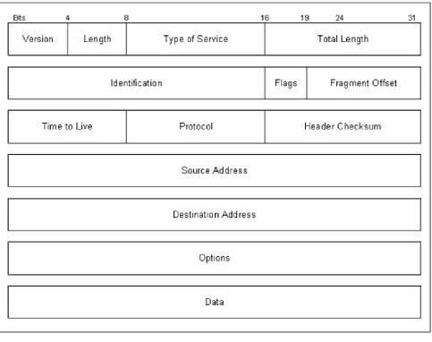
During an analysis session, or sniffer capture, it is necessary to differentiate between different types of packet captur es. The following describes the IP packet and the 14 fields therein, as illustrated in Figure 1.2.
• Version. The IP version currently used.
• IP Header Length (Length). The datagram header length in 32-bit words.
• Type -of-Service (ToS). How the upper-layer protocol (the layer immediately above, such as transport protocols like TCP and UDP) intends to handle the current datagram and assign a level of importance.
• Total Length. The length, in bytes, of the entire IP packet.
• Identification. An integer used to help piece together datagram fragments.
• Flag. A 3-bit field, where the first bit specifies whether the packet can be fragmented. The second bit indicates whether the packet is the last fragment in a series. The final bit is not used at this time.
• Fragment Offset. The location of the fragment’s data, relative to the opening data in the original datagram. This allows for proper reconstruction of the original datagram.
• Time-to-Live (TTL). A counter that decrements to zero to keep packets from endlessly looping. At the zero mark, the packet is dropped.
• Protocol. Indicates the upper-layer protocol receiving the incoming packets. • Header Checksum. Ensures the integrity of the IP header.
• Source Address/Destination Address. The sending and receiving nodes (station, server, and/or router).
• Data. Upper- layer information.
Key fields to note include the Source Address, Destination Address, Options, and Data.
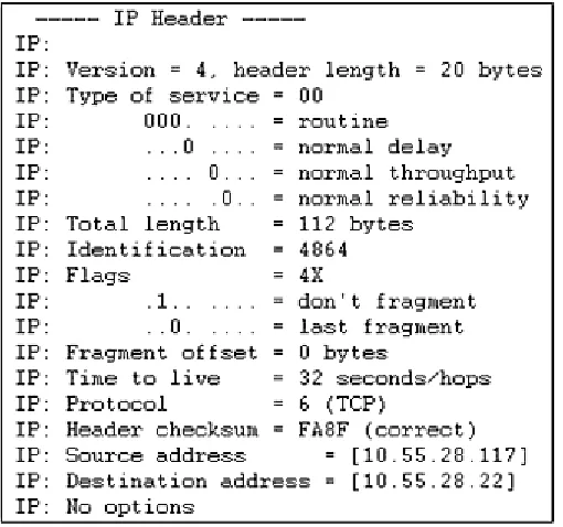
[image:23.596.75.324.164.406.2]Now let’s look at actual sniffer snapshots of IP Headers in Figures 1.3a and 1.3b to compare with the fields in the previous figure.
Figure 1.3a Extracted during the transmission of an Internet Control Message Protocol (ICMP) ping test (ICMP is explained later in this chapter).
Figure 1.3b Extracted during the transmission of a NetBIOS User Datagram Protocol (UDP) session request (these protocols are described later in this chapter and in Chapter 2).
[image:23.596.74.329.463.702.2]IP datagrams are the very basic, or fundamental, transfer unit of the Internet. An IP datagram is the unit of data commuted between IP modules. IP datagrams have headers with fields that provide routing information used by infrastructure equipment such as routers (see Figure 1.4).
Figure 1.4 An IP datagram.
Be aware that the data in a packet is not really a concern for the IP. Instead, IP is concerned with the control information as it pertains to the upper-layer protocol. This information is stored in the IP header, which tries to deliver the datagram to its destination on the local network or over the Internet. To understand this relationship, think of IP as the method and the datagram as the means.
The IP header is the primary field for gathering information, as well as for gaining control.
It is important to understand the methods a datagram uses to travel across networks. To sufficiently travel across the Internet, over physical media, we want some guarantee that each datagram travels in a physical frame. The process of a datagram traveling across media in a frame is called encapsulation.
Now, let’s take a look at an actual traveling datagram scenario to further explain these traveling datagram methods (see Figure 1.5). This example includes corporate connectivity between three branch offices, over the Internet, linking Ethernet, Token Ring, and FDDI (Fiber Distributed Data Interface) or fiber redundant Token Ring networks.
An ideal situation is one where an entire IP datagram fits into a frame; and the network it is traveling across supports that particular transfer size. But as we all know ideal situations are rare. One problem with our traveling datagram is that networks enforce a maximum transfer unit (MTU) size, or limit, on the size of transfer. To further confuse the issue, different types of networks enforce their own MTU; for example, Ethernet has an MTU of 1500, FDDI uses 4470 MTU, and so on. When datagrams traveling in frames cross network types with different specified size limits, routers must sometimes divide the datagram to accommodate a smaller MTU. This process is called fragmentation.
Routers provide the fragmentation process of datagrams, and as such, become vulnerable to passive and intrusive attacks.
IP Addresses, Classes, Subnet Masks
Communicating on the Internet would be almost impossible if a system of unique addressing were not used. To prevent the use of duplicate addresses, routing between nodes is based on addresses assigned from a pool of classes, or range of available addresses, from the InterNetwork Information Center (InterNIC). InterNIC assigns and controls all network addresses used over the Internet by assigning addresses in three classes (A, B, and C), which consist of 32-bit numbers. By default, the usable bits for Classes A, B, and C are 8, 16, and 24 respectively. Addresses from this pool have been assigned and utilized since the 1970s, and they include the ranges shown in Figure 1.6; an example of an IP address is shown in Figure 1.7.
Figure 1.7 IP address example with four octets.
The first octet (206) indicates a Class C (Internet-assigned) IP address range with the format Network.Network.Network.Host with a standard mask binary indicating 255.255.255.0. This means that we have 8 bits in the last octet for hosts. The 8 bits that make up the last, or fourth, octet are understood by infrastructure equipment such as routers and software in the following manner:
Bit: 1 2 3 4 5 6 7 8
Value: 128 64 32 16 8 4 2 1 = 255 (254 usable hosts) In this example of a full Class C, we only have 254 usable IP addresses for hosts; 0 and 255 cannot be used as host addresses because the network number is 0 and the broadcast address is 255.
With the abundant utilization of Class B address space and the flooding of requested Class C addresses, a Classless Interdomain Routing (CIR) system was introduced in the early 1990s. Basically, a route is no longer an IP address; a route is now an IP address and mask, allowing us to break a network into subnets and supernets. This also drastically reduces the size of Internet routing tables.
It is important to understand IP address masking and subnetting for performing a security analysis, penetration hacking, and spoofing. There’s more information on these topics later in this chapter.
Subnetting, VLSM, and Unraveling IP the Easy Way
Figure 1.8 Real- world IP network example.
Example 1
Let’s take a look at a real- world scenario of allocating IP addresses for a routed network (Figure 1.8). Given: 206.0.125.0 (NIC assigned Class C). In this scenario, we need to divide our Class C address block to accommodate three usable subnets (for offices A, B, and C) and two subnets for future growth. Each subnet or network must have at least 25 available node addresses. This process can be divided into five steps.
Step 1
Four host addresses will be required for each of the office’s router interfaces: Router 1 Ethernet 0, Router 2 Ethernet 0/Ethernet 1, and Router 3 Token Ring 0 (see Figure 1.9).
Step 2
Figure 1.9 Real- world network example interface requirement chart.
See Appendix A: ‘‘IP Reference Table and Subnetting Charts,” as well as an IP Subne tting Calculator found on the CD for quick calculations. It is important to understand this process when searching for all possible hosts on a network during a discovery analysis.
Figure 1.10 Class C subnet chart by number of subnets versus number of hosts per subnet.
• Bits in Subnet Mask: Keeping in mind the information given earlier, let’s further explore the subnet mask bit breakdown. When a bit is used, we indicate this with a 1:
3 Bits: 1 1 1
Value: 128 64 32 16 8 4 2 1 When a bit is not used, we indicate this with a 0:
3 Bits: 0 0 0 0 0
Value: 128 64 32 16 8 4 2 1 SUBNET MASK
3 Bits: 1 1 1 0 0 0 0 0
• Number of Subnets: Remember, in this scenario we need to divide our Class C address block to accommodate three usable subnets (for offices A, B, and C) and two subnets for future growth with at least 25 available node addresses per each of the five networks.
• To make this process as simple as possible, let’s start with the smaller number—that is, 5 for the required subnets or networks, as opposed to 25 for the available nodes needed per network. To solve for the required subnets in Figure 1.9), we’ll start with the following equation, where we’ll solve for n in 2n – 2, being sure to cover the required five subnets or networks.
• Let’s start with the power of 2 and work our way up: 22 – 2 = 2 23 – 2 = 6 24 – 2 = 14
• The (3rd power) in the equation indicates the number of bits in the subnet mask. Here we see that 23 – 2 = 6 subnets if we use these 3 bits. This will cover the required five subnets with an additional subnet (or network) left over.
• Number of Hosts per Subnet: Now let’s determine the number of bits left over for available host addresses. In this scenario, we will be using 3 bits in the mask for subnetting. How many are left over?
• Out of the given 32 bits that make up IP addresses, the default availability (for networks versus hosts), as previously explained, for Classes A, B, and C blocks are as follows:
Class A: 8 bits Class B: 16 bits Class C: 24 bits
Our scenario involves a Class C block assigned by InterNIC. If we subtract our default bit availability for Class C of 24 bits (as shown) from the standard 32 bits that make up IP addresses, we have 8 bits remaining for networks versus hosts for Class C blocks.
Next, we subtract our 3 bits used for subnetting from the total 8 bits remaining for network versus hosts, which gives us 5 bits left for actual host addressing:
3 Bits: 1 1 1 0 0 0 0 0 Value: 128 64 32 (16 8 4 2 1)
5 bits left
Let’s solve an equation to see if 5 bits are enough to cover the required available node addresses of at least 25 per subnet or network:
25 – 2 = 30
Placing the remaining 5 bits back into our equation gives us the available node addresses per subnet or network, 25 – 2 = 30 host addresses per six subnets or networks (remember, we have an additional subnet left over).
Step 3
Now that we have determined the subnet mask, in this case 255.255.255.224 (3 bits), we need to calculate the actual network numbers or range of IP addresses in each network.
An easy way to accomplish this is by setting the host bits to 0. Remember, we have 5 bits left for hosts:
3 Bits: 1 1 1 0 0 0 0 0 Value: 128 64 32 (16 8 4 2 1)
5 host bits
left
With the 5 host bits set to 0, we set the first 3 bits to 1 in every variation, then calculate the value (for a shortcut, take the first subnet value=32 and add it in succession to reveal all six subnets):
3 Bits: 0 0 1 0 0 0 0 0 Value: 128 64 32 (16 8 4 2 1) 32 = 32 3 Bits: 0 1 0 0 0 0 0 0 Value: 128 64 32 (16 8 4 2 1) 64 = 64 3 Bits: 0 1 1 0 0 0 0 0 Value: 128 64 32 (16 8 4 2 1)
64+ 32 = 96
3 Bits: 1 0 0 0 0 0 0 0 Value: 128 64 32 (16 8 4 2 1)
128 = 128
3 Bits: 1 0 1 0 0 0 0 0 Value: 128 64 32 (16 8 4 2 1)
128+ 32 = 160
3 Bits: 1 1 0 0 0 0 0 0 Value: 128 64 32 (16 8 4 2 1)
128+ 64 = 192
Now let’s take a look at the network numbers of our subnetted Class C block with mask 255.255.255.224:
Now that we have solved the network numbers, let’s resolve each network’s broadcast address by setting host bits to all 1s. The broadcast address is defined as the system that copies and delivers a single packet to all addresses on the network. All hosts attached to a network can be notified by sending a packet to a common address known as the broadcast address:
3 Bits: 0 0 1 1 1 1 1 1 Value: 128 64 32 (16 8 4 2 1) 32+ 16+ 8+ 4+ 2+ 1 = 63 3 Bits: 0 1 0 1 1 1 1 1 Value: 128 64 32 (16 8 4 2 1) 64 +16 +8 +4 +2 +1 = 95 3 Bits: 0 1 1 1 1 1 1 1 Value: 128 64 32 (16 8 4 2 1) 64+ 32+ 16+ 8+ 4+ 2+ 1 = 127 3 Bits: 1 0 0 1 1 1 1 1 Value: 128 64 32 (16 8 4 2 1) 128+ 16+ 8+ 4+ 2+ 1 = 159 3 Bits: 1 0 1 1 1 1 1 1 Value: 128 64 32 (16 8 4 2 1) 128+ 32+ 16+ 8+ 4+ 2+ 1 = 191 3 Bits: 1 1 0 1 1 1 1 1 Value: 128 64 32 (16 8 4 2 1) 128+ 64+ 16+ 8+ 4+ 2+ 1 = 223
Let’s take a look at the network broadcast addresses of our subnetted Class C block with mask 255.255.255.224:
206.0.125.63 206.0.125.95 206.0.125.127 206.0.125.159 206.0.125.191 206.0.125.223 Step 5
Figure 1.11 Available IP addresses for our networks.
Unraveling IP with Shortcuts
Let’s take a brief look at a shortcut for determining a network address, given an IP address.
Given: 206.0.139.81 255.255.255.224. To calculate the network address for this host, let’s map out the host octet (.81) and the subnet- masked octet (.224) by starting from the left, or largest, number: (.81) Bits: 1 1 1
Value: 128 64 32 16 8 4 2 1
64+ 16+ 1=81
(.224) Bits: 1 1 1 Value: 128 64 32 16 8 4 2 1
128+ 64+ 32 = 224
Now we can perform a mathematic “logical AND” to obtain the network address of this host (the value 64 is the only common bit):
(.81) Bits: 1 1 1 Value: 128 64 32 16 8 4 2 1 (.224) Bits: 1 1 1
Value: 128 64 32 16 8 4 2 1
64 =64
We simply put the 1s together horizontally, and record the common value (205.0.125.64).
Example 2
Given: 07.247.60.0 (InterNIC-assigned Class C) 255.255.255.0. In this scenario, we need to divide our Class C address block to accommodate 10 usable subnets. Each subnet or network must have at least 10 available node addresses. This example requires four steps to complete.
Step 1
• Number of Subnets: Remember, in this scenario we need to divide our Class C address block to accommodate 10 usable with at least 10 available node addresses per each of the 10 networks.
• Let’s start with the number 10 for the required subnets and the following equation, where we’ll solve for n in 2n – 2, being sure to cover the required 10 subnets or networks.
• We’ll begin with the power of 2 and work our way up: 22 – 2 = 2 23 – 2 = 6 24 – 2 = 14
• In this equation, the (4th power) indicates the number of bits in the subnet mask. Note that 24 – 2 = 14 subnets if we use these 4 bits. This will cover the required 10 subnets, and leave four additional subnets (or networks).
• SUBNET MASK
4 Bits: 1 1 1 1 0 0 0 0 Value: 128 64 32 16 8 4 2 1
Value: 128+ 64+ 32+ 16 =240 (mask = 255.255.255.240)
• Number of Hosts per Subnet: Now we’ll determine the number of bits left over for available host addresses. In this scenario, we will be using 4 bits in the mask for subnetting. How many are left over?
Remember, out of the given 32 bits that make up IP addresses, the default availability (for networks versus hosts), as previously explained, for Classes A, B, and C blocks is as follows:
Class A: 8 bits Class B: 16 bits Class C: 24 bits
• Our scenario involves a Class C block assigned by InterNIC. If we subtract our default bit availability for Class C of 24 bits (as shown) from the standard 32 bits that make up IP addresses, we have 8 bits remaining for networks versus hosts for Class C blocks.
• Next, we subtract the 4 bits used for subnetting from the total 8 bits remaining for network versus hosts, which gives us 4 bits left for actual host addressing:
4 Bits: 1 1 1 1 0 0 0 0 Value: 128 64 32 16 (8 4 2 1)
4 bits left
24 – 2 = 14
Placing the remaining 4 bits back into our equation gives us the available node addresses per subnet or network: 24 – 2 = 14 host addresses per 14 subnets or networks (remember, we have four additional subnets left over).
From these steps, we can divide our Class C block using 4 bits to give us 14 subnets with 14 host addresses each.
Step 2
Now that we have determined the subnet mask, in this case 255.255.255.240 (4 bits), we need to calculate the actual network numbers or range of IP addresses in each network. An easy way to accomplish this is by setting the host bits to 0. Remember, we have 4 bits left for hosts:
4 Bits: 1 1 1 1 0 0 0 0
Value: 128 64 32 16 (8 4 2 1)
4 host bits left
With the 4 host bits set to 0, we set the first 4 bits to 1 in every variation, then calculate the value: 4 Bits: 0 0 0 1 0 0 0 0
Value: 128 64 32 16 (8 4 2 1) 16 = 16 4 Bits: 0 0 1 0 0 0 0 0 Value: 128 64 32 16 (8 4 2 1)
32 = 32
and so on to reveal our 14 subnets or networks. Recall the shortcut in the first example; we can take our first value (=16) and add it in succession to equate to 14 networks:
First subnet = .16 Second subnet = .32 (16+16) Third subnet = .48 (32+16) 207.247.60.16 207.247.60.32 207.247.60.48 207.247.60.64 207.247.60.80 207.247.60.96 207.247.60.112 207.247.60.128 207.247.60.144 207.247.60.160 207.247.60.176 207.247.60.192
207.247.60.208 207.247.60.224
Step 3
Now that we have solved the network numbers, let’s resolve each network’s broadcast address. This step is easy. Remember, the broadcast address is the last address in a network before the next network address; therefore:
FIRST NETWORK SECOND NETWORK
207.247.60.16 (.31) 207.247.60.32 (.47) 207.247.60.48 (.63)
FIRST BROADCAST SECOND BROADCAST Step 4
So what are the available IP addresses for each network? The answer is right in the middle of step 3. Keep in mind, the available IP addresses for each network fall between the network and broadcast addresses:
FIRST NETWORK SECOND NETWORK
207.247.60.16 (.31) 207.247.60.32 (.47) 207.247.60.48
FIRST BROADCAST SECOND BROADCAST
(Network 1 addresses: .17 - .30) (Network 2 addresses: .33 - .46)
ARP/RARP Engineering: Introduction to Physical Hardware Address Mapping
Now that we have unearthed IP addresses and their 32-bit addresses, packet/datagram flow and subnetting, we need to discover how a host station or infrastructure equipment, such as a router, match an IP address to a physical hardware address. This section explains the mapping process that makes communication possible. Every interface, or network interface card (NIC), in a station, server, or infrastructure equipment has a unique physical address that is programmed by and bound internally by the manufacturer.
One goal of infrastructure software is to communicate using an assigned IP or Internet address, while hiding the unique physical address of the hardware. Underneath all of this is the address mapping of the assigned address to the actual physical hardware address. To map these addresses, programmers use the Address Resolution Protocol (ARP).
Basically, ARP is a packet that is broadcasted to all hosts attached to a physical network. This packet contains the IP address of the node or station with which the sender wants to communicate. Other hosts on the network ignore this packet after storing a copy of the sender’s IP/hardware address mapping. The target host, however, will reply with its hardware address, which will be returned to the sender, to be stored in its ARP response cache. In this way, communication between these two nodes can ensue (see Figure 1.12).
Figure 1.12 ARP resolution.
ARP Encapsulation and Header Formatting
It is important to know that ARP is not an Internet protocol; moreover, ARP does not leave the local logical network, and therefore does not need to be routed. Rather, ARP must be broadcasted, whereby it communicates with every host interface on the network, traveling from machine to machine encapsulated in Ethernet packets (in the data portion).
[image:36.596.75.476.290.583.2]ARP is broadcasted to reach every interface on the network. These hosts can store this information to be used later for potential masquerading. See Chapter 8 for more information on spoofing.
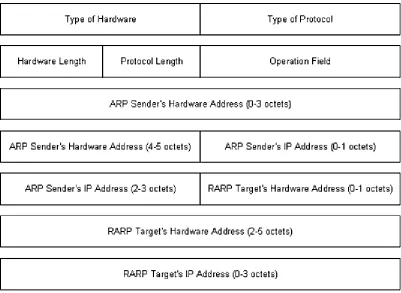
Figure 1.13 illustrates the encapsulation of an ARP packet including the Reverse Address Resolution Protocol (RARP) (which is discussed in the next section). The packet components are defined in the following list:
Figure 1.13 An ARP/RARP packet.
Type of Hardware. Specifies the target host’s hardware interface type (1 for Ethernet). Type of Protocol. The protocol type the sender has
supplied (0800 for an IP address). Hardware Length. The length of the hardware address. Protocol Length. The length of the protocol address. Operation Field. Specifies whether either an ARP
ARP Sender’s Hardware Address. Sender’s hardware address. ARP Sender’s IP Address. Sender’s IP address.
RARP Targets Hardware Address.
Target’s hardware address. RARP Targets IP Address. Target’s IP address.
Keep in mind that ARP packets do not have a defined header format. The length fields shown in Figure 1.13 enable ARP to be implemented with other technologies.
RARP Transactions, Encapsulation
The Reverse Address Resolution Protocol (RARP), to some degree, is the opposite of ARP. Basically, RARP allows a station to broadcast its hardware address, expecting a server daemon to respond with an available IP address for the station to use. Diskless machines use RARP to obtain IP addresses from RARP servers.
It is important to know that RARP messages, like ARP, are encapsulated in Ethernet frames (see Figure 1.14, Excerpt from Figure 1.13). Likewise, RARP is broadcast from machine to machine, communicating with every host interface on the network.
Figure 1.14 Excerpt from Figure 1.13. RARP Service
The RARP Daemon (RARPd) is a service that responds to RARP requests. Diskless systems typically use RARP at boot time to discover their 32-bit IP address, given their 48-bit hardware Ethernet address. The booting machine sends its Ethernet address, encapsulated in a frame as a RARP request message. The server running RARPd must have the machine’s name-to-IP-address entry, or it must be available from the Domain Name Server (DNS) with its name-to-Ethernet-address. With these sources available, the RARPd server maps this Ethernet address with the corresponding IP address.
RARP, with ARP spoofing, gives a hacker the ability to passively request an IP address and to passively partake in network communications, typically unnoticed by other nodes.
Transmission Control Protocol
TCP/IP is predominantly based on TCP functionality, which is based on IP, to make up the TCP/IP suite. These features describe a connection-oriented process of communication establishment.
There are many components that result in TCP’s reliable service delivery. Following are some of the main points:
• Streams. Data is systematized and transferred as a stream of bits, organized into 8-bit octets or bytes. As these bits are received, they are passed on in the same manner.
• Buffer Flow Control. As data is passed in streams, protocol software may divide the stream to fill specific buffer sizes. TCP manages this process, and assures avoidance of a buffer overflow. During this process, fast-sending stations may be stopped periodically to keep up with slow-receiving stations.
• Virtual Circuits. When one station requests communication with another, both stations inform their application programs, and agree to communicate. If the link or communications between these stations fail, both stations are made aware of the breakdown and inform their respective software applications. In this case, a coordinated retry is attempted.
• Full Duplex Connectivity. Stream transfer occurs in both directions, simultaneously, to reduce overall network traffic.
Figure 1.15 TCP windowing example. Sequencing and Windowing
TCP organizes and counts bytes in the data stream using a 32-bit sequence number. Every TCP packet contains a starting sequence number (first byte) and an acknowledgment number (last byte). A concept known as a sliding window is implemented to make stream transmissions more efficient. The sliding window uses bandwidth more effectively, because it will allow the transmission of multiple packets before an acknowledgment is required.
At any point, the receiver may indicate a window size of 0, in which case the sender will not send any more bytes until the window size is greater. A typical cause for this occurring is a buffer overflow.
TCP Packet Format and Header Snapshots
Keeping in mind that it is important to differentiate between captured packets—whether they are TCP, UDP, ARP, and so on—take a look at the TCP packet format in Figure 1.16, whose components are defined in the following list:
Figure 1.16 A TCP packet.
Source Port. Specifies the port at which the source processes send/receive TCP services.
Destination Port. Specifies the port at which the destination processes send/receive TCP services.
Sequence Number. Specifies the first byte of data or a reserved sequence number for a future process.
Acknowledgment Number.
The sequence number of the very next byte of data the sender should receive.
Data Offset. The number of 32-bit words in the header. Reserved. Held for future use.
Flags. Control information, such as SYN, ACK, and FIN bits, for connection establishment and termination.
Checksum. Specifies any damage to the header that occurred during transmission.
Urgent Pointer. The optional first urgent byte in a packet, which indicates the end of urgent data.
Options. TCP options, such as the maximum TCP segment size.
Data. Upper- layer information.
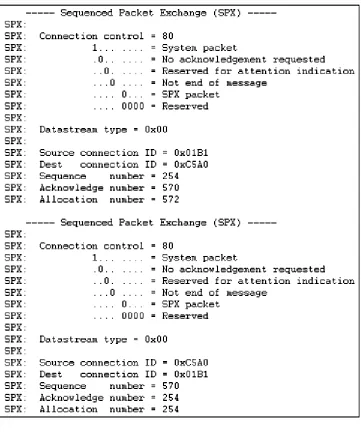
Now take a look at the snapshot of a TCP header, shown in Figure 1.17a, and compare it with the fields shown in Figure 1.17b.
Ports, Endpoints, Connection Establishment
TCP enables simultaneous communication between different application programs on a single machine. TCP uses port numbers to distinguish each of the receiving station’s destinations. A pair of endpoints identifies the connection between the two stations, as mentioned earlier. Colloquially, these endpoints are defined as the connection between the two stations’ applications as they communicate; they are defined by TCP as a pair of integers in this format: (host, port). The host is the station’s IP address, and port is the TCP port number on that station. An example of a station’s endpoint is:
206.0.125.81:1026 (host)(port)
An example of two stations’ endpoints during communication is:
STATION 1 STATION 2
206.0.125.81:1022 207.63.129.2:26 (host)(port) (host)(port)
This technology is very important in TCP, as it allows simultaneous communications by assigning separate ports for each station connection.
Figure 1.17a Extracted from an HTTP Internet Web server transmission.
Figure 1.17b Extracted from a sliding window sequence transmission.
User Datagram Protocol
The User Datagram Protocol (UDP) operates in a connectionless fashion; that is, it provides the same unreliable, datagram delivery service as IP. Unlike TCP, UDP does not send SYN/ACK bits to assure delivery and reliability of transmissions. Moreover, UDP does not include flow control or error recovery functionality. Consequently, UDP messages can be lost, duplicated, or arrive in the wrong order. And because UDP contains smaller headers, it expends less network throughput than TCP and so can arrive faster than the receiving station can process them.
UDP does not include flow control or error recovery, and can be easily duplicated.
UDP Formatting, Encapsulation, and Header Snapshots
UDP messages are called user datagrams. These datagrams are encapsulated in IP, including the UDP header and data, as it travels across the Internet. Basically, UDP adds a header to the data that a user sends, and passes it along to IP. The IP layer then adds a header to what it receives from UDP. Finally, the network interface layer inserts the datagram in a frame before sending it from one machine to another.
As just mentioned, UDP messages contain smaller headers and consume fewer overheads than TCP. The UDP datagram format is shown in Figure 1.18, and its components are defined in the following list.
Source/Destination Port. A 16-bit UDP port number used for datagram processing. Message Length. Specifies the number of octets in the UDP datagram. Checksum. An optional field to verify datagram delivery.
Data. The data handed down to the TCP protocol, including upper-layer headers.
Snapshots of a UDP header are given in Figure 1.19.
Figure 1.18 Illustration of a UDP datagram.
Multiplexing, Demultiplexing, and Port Connections
UDP provides multiplexing (the method for multiple signals to be transmitted concurrently into an input stream, across a single physical channe l) and demultiplexing (the actual separation of the streams that have been multiplexed into a common stream back into multiple output streams) between protocol and application software.
Figure 1.19 Extracted after the IP portion of a domain name resolution from a DNS request transmission (discussed in Chapter 5).
Internet Control Message Protocol
The Internet Control Message Protocol (ICMP) delivers message packets, reporting errors and other pertinent information to the sending station or source. Hosts and infrastructure equipment use this mechanism to communicate control and error information, as they pertain to IP packet processing. ICMP Format, Encapsulation, and Delivery
ICMP message encapsulation is a two- fold process. The messages are encapsulated in IP datagrams, which are encapsulated in frames, as they travel across the Internet. Basically, ICMP uses the same unreliable means of communications as a datagram. This means that ICMP error messages may be lost or duplicated.
The ICMP format includes a message type field, indicating the type of message; a code field that includes detailed information about the type; and a checksum field, which provides the same functionality as IP’s checksum (see Figure 1.20). When an ICMP message reports an error, it includes the header and data of the datagram that caused the specified problem. This helps the receiving station to understand which application and protocol sent the datagram. (The next section has more information on ICMP message types.)
Like UDP, ICMP does not include flow control or error recovery, and so can be easily duplicated.
Figure 1.21 ICMP message chart.
ICMP Messages, Subnet Mask Retrieval
There are many types of useful ICMP messages; Figure 1.21 contains a list of several, which are described in the following list.
• Echo Reply (Type 0)/Echo Request (Type 8). The basic mechanism for testing possible communication between two nodes. The receiving station, if available, is asked to reply to the ping. An example of a ping is as follows:
STEP 1: BEGIN ECHO REQUEST Ping 206.0.125.81 (at the command prompt) STEP 2: BEGIN ECHO REPLY
Reply from 206.0.125.81: bytes-32 time<10ms TTL=128 (from receiving station 206.0.125.81) Reply from 206.0.125.81: bytes-32 time<10ms TTL=128
Reply from 206.0.125.81: bytes-32 time<10ms TTL=128 Reply from 206.0.125.81: bytes-32 time<10ms TTL=128
Destination Unreachable (Ty pe 3). There are several issuances for this message type, including when a router or gateway does not know how to reach the destination, when a protocol or application is not active, when a datagram specifies an unstable route, or when a router must fragment the size of a datagram and cannot because the Don’t Fragment Flag is set. An example of a Type 3 message is as follows:
STEP 1: BEGIN ECHO REQUEST Ping 206.0.125.81 (at the command prompt) STEP 2: BEGIN ECHO REPLY
Destination host unreachable. Destination host unreachable. Destination host unreachable.
• Source Quench (Type 4). A basic form of flow control for datagram delivery. When datagrams arrive too quickly at a receiving station to process, the datagrams are discarded. During this process, for every datagram that has been dropped, an ICMP Type 4 message is passed along to the sending station. The Source Quench messages actually become requests, to slow down the rate at which datagrams are sent. On the flip side, Source Quench messages do not have a reverse effect, whereas the sending station will increase the rate of transmission.
• Route Redirect (Type 5). Routing information is exchanged periodically to accommodate network changes and to keep routing tables up to date. When a router identifies a host that is using a nonoptional route, the router sends an ICMP Type 5 message while forwarding the datagram to the destination network. As a result, routers can send Type 5 messages only to hosts directly connected to their networks.
• Datagram Time Exceeded (Type 11). A gateway or router will emit a Type 11 message if it is forced to drop a datagram because the TTL (Time-to-Live) field is set to 0. Basically, if the router detects the TTL=0 when intercepting a datagram, it is forced to discard that datagram and send an ICMP message Type 11.
• Datagram Parameter Problem (Type 12). Specifies a problem with the datagram header that is impeding further processing. The datagram will be discarded, and a Type 12 message will be transmitted.
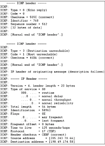
Figure 1.22 ICMP header sniffer capture.
Information Request (Type 15)/Information Reply (Type 16). As an alternative to RARP (described previously), stations use Type 15 and Type 16 to obtain an Internet address for a network to which they are attached. The sending station will emit the message, with the network portion of the Internet address, and wait for a response, with the host portion (its IP address) filled in.
• Address Mask Request (Type 17)/Address Mask Reply (Type 18). Similar to an Information Request/Reply, stations can send Type 17 and Type 18 messages to obtain the subnet mask of the network to which they are attached. Stations may submit this request to a known node, such as a gateway or router, or broadcast the request to the network.
in more detail in a subsequent chapter. ICMP Header Snapshots
Figure 1.22 on page 35 contains snapshots of an ICMP Header. The first was extracted after the IP portion of an ICMP ping test transmission; the second was extracted during an unreachable ping test.
Moving Forward
CHAPTER
2
NetWare and NetBIOS Technology
This chapter addresses, respectively, two topics important to the broader topic of communication protocols: NetWare and NetBIOS technology. NetWare is a network operating system developed by Novell in the early 1980s. NetBIOS is an application programming interface (API, a technology that enables an application on one station to communicate with an application on another station). IBM first introduced it for the local area network (LAN) environment. NetBIOS provides both connectionless and connection-oriented data transfer services. Both NetWare and NetBIOS were among the most popular network operating systems during the mid-to-late 1980s and the early 1990s.
NetWare: Introduction
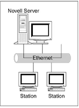
NetWare provides a variety of server daemon services and support, based on the client/server architecture. A client is a station that requests services, such as file access, from a server (see Figure 2.1). Internetwork Packet Exchange (IPX) was the original NetWare protocol used to route packets through an internetwork.
Internetwork Packet Exchange
[image:48.596.74.209.471.656.2]IPX is a connectionless datagram protocol, and, as such, is similar to unreliable datagram delivery offered by the Internet Protocol (discussed in Chapter 1).
Figure 2.1 Client/server diagram.
Because the host portion of an IP network address has no equivalence to a MAC address, IP nodes must use the Address Resolution Protocol (ARP) to determine the destination MAC address (see Chapter 1).
IPX Encapsulation, Format, Header Snapshots
To process upper- layer protocol information and data into frames, NetWare IPX supports several encapsulation schemes. Among the most popular encapsulation types are Novell Proprietary, 802.3, Ethernet Version 2, and Ethernet SNAP, which are defined in the following list:
Figure 2.2 IPX Address.
• Novell Proprietary. Novell’s initial encapsulation type, also known as Novel Ethernet 802.3 and 802.3 Raw.
• 802.3. The standard IEEE 802.3 format, also known as Novell 802.2. • Ethernet II. Includes a standard Ethernet Version 2 header.
• Ethernet SNAP. An extension of 802.3.
IPX network numbers play a primary role in the foundation for IPX internetwork packet exchange between network segments. Every segment is assigned a unique network address to which packets are routed for node destinations. For a protocol to identify itself with IPX and communicate with the network, it must request a socket number. Socket numbers ascertain the identity of processes within a station or node. IPX formatting is shown in Figure 2.3; its fields are defined as follows:
• Checksum. The default for this field is no checksum; however, it can be configurable to perform on the IPX section of the packet.
• Packet Length. The total length of the IPX packet.
• Transport Control. When a packet is transmitted and passes through a router, this field is incremented by 1. The limit for this field is 15 (15 hops or routers). The router that increments this field number to 16 will discard the packet.
• Packet Type. Services include:
(Type 0) Unknown packet type (Type 1) Routing information packet
(Type 4) IPX packet or used by the Service Advertisement Protocol (SAP; explained in the next section)
Figure 2.3 An IPX packet.
(Type 17) NetWare core protocol packet (Type 20) IPX NetBIOS broadcast
• Destination Network. The destinatio n network to which the destination node belongs. If the destination is local, this field is set to 0.
• Destination Node. The destination node address.
• Destination Socket. The destination node’s process socket address.
• Source Network. The source network to which the source node belongs. If the source is unknown, this field is set to 0.
• Source Node. The source node address.
• Source Socket. The source node’s process socket address that transmits the packet. • Data. The IPX data, often including the header of a higher- level protocol.
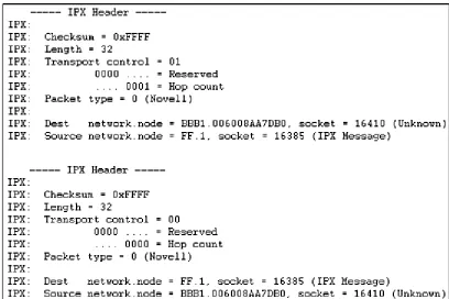
Keeping in mind the fields in Figure 2.3, now take a look at Figure 2.4 to compare the fields an actual IPX header captures during transmission.
Figure 2.5 SAP flow network diagram.
Service Advertisement Protocol
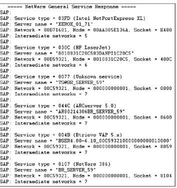
The Service Advertisement Protocol (SAP) is a method by which network resources, such as file servers, advertise their addresses and the services they provide. By default, these advertisements are sent every 60 seconds. A SAP identifier (hexadecimal number) indicates the provided services; for example, Type 0x0007 specifies a print server. Let’s take a look at a real world scenario of SAP in Figure 2.5.
In this scenario, the print and file server will advertise SAP messages every 60 seconds. The router will listen to SAPs, then build a table of the known advertised services with their network addresses. As the router table is created, it too will be sent out (propagated) to the network every 60 seconds. If a client (Station A) sends a query and requests a particular printer process from the print server, the router will respond with the network address of the requested service. At this point, the client (Station A) will be able to contact the service directly.
[image:51.596.74.285.46.297.2]Intercepting unfiltered SAP messages as they propagate the network relinquishes valuable network service and addressing information.
Figure 2.6 A SAP packet.
SAP Format, Header Snapshots, Filters
• Operation. The type of operation: a SAP request or response. • Source Type. The type of service provided:
Type 0x0004: File Server Type 0x0005: Job Server Type 0x0007: Print Server Type 0x0009: Archive Server Type 0x000A: Job Queue Type 0x0021: SNA Gateway Type 0x002D: Time Sync Type 0x002E: Dynamic SAP
Type 0x0047: Advertising Print Server Type 0x004B: Btrieve VAP
Type 0X004C: SQL VA Type 0x0077: Unknown Type 0x007A: NetWare VMS
Type 0x0098: NetWare Access Server Type 0x009A: Named Pipes Server Type 0x009E: NetWare-UNIX Type 0x0107: NetWare 386 Type 0x0111: