Ames Laboratory Conference Papers, Posters, and
Presentations
Ames Laboratory
1-2014
Developing an Integrated Computational
Environment for the Detailed Design of a Mixing
Impeller
Benjamin M. Sloan
Iowa State University, [email protected]
Sunil Suram
Iowa State UniversityKenneth M. Bryden
Iowa State University, [email protected]
Follow this and additional works at:
http://lib.dr.iastate.edu/ameslab_conf
Part of the
Mechanical Engineering Commons
This Conference Proceeding is brought to you for free and open access by the Ames Laboratory at Iowa State University Digital Repository. It has been accepted for inclusion in Ames Laboratory Conference Papers, Posters, and Presentations by an authorized administrator of Iowa State University Digital Repository. For more information, please [email protected].
Recommended Citation
Sloan, Benjamin M.; Suram, Sunil; and Bryden, Kenneth M., "Developing an Integrated Computational Environment for the Detailed Design of a Mixing Impeller" (2014).Ames Laboratory Conference Papers, Posters, and Presentations. 76.
Developing an Integrated Computational Environment for the Detailed
Design of a Mixing Impeller
Abstract
Digital manufacturing significantly reduces the expense and time required to produce custom products.
Utilizing this technology, a customized product can be quickly manufactured. But the timescale and expense
of the engineering design workflows used to develop these customized products have not been adapted from
the workflows used in mass production due to the development of high fidelity models. But with digital
manufacturing the economies of scale are eliminated such that producing many unique designs or many of the
same designs result in the same manufacturing cost. Developing a design workflow that utilizes the developed
and validated high fidelity models of the already produced design can reduce the amount of time and expense
developing a slightly varied customized design. Reduced order modeling enables this reuse and magnification
of existing high fidelity models by creating a computationally inexpensive representation of a model from high
fidelity data. This thesis explores the integration of reduced order modeling and detailed analysis into the
engineering design workflow developing a customized design using digital manufacturing. Specifically
detailed analysis is coupled with proper orthogonal decomposition to enable the exploration of the design
space while simultaneously shaping the model representing the design. This revised workflow is examined
using the design of a laboratory scale overhead mixing impeller. The case study presented here is compared
with the design of the Kar Dynamic Mixer developed by the Dow Chemical Company. The result of which is a
customized design for a refined set of operating conditions with improved performance.
Disciplines
Developing an Integrated Computational Environment for
the Detailed Design of a Mixing Impeller
Benjamin M. Sloan1, Sunil Suram2 and Kenneth M. Bryden3
Iowa State University, Ames, IA, 50011
Digital manufacturing significantly reduces the expense and time required to produce custom products. Utilizing this technology, a customized product can be quickly manufactured. But the timescale and expense of the engineering design workflows used to develop these customized products have not been adapted from the workflows used in mass production due to the development of high fidelity models. But with digital manufacturing the economies of scale are eliminated such that producing many unique designs or many of the same designs result in the same manufacturing cost. Developing a design workflow that utilizes the developed and validated high fidelity models of the already produced design can reduce the amount of time and expense developing a slightly varied customized design. Reduced order modeling enables this reuse and magnification of existing high fidelity models by creating a computationally inexpensive representation of a model from high fidelity data. This thesis explores the integration of reduced order modeling and detailed analysis into the engineering design workflow developing a customized design using digital manufacturing. Specifically detailed analysis is coupled with proper orthogonal decomposition to enable the exploration of the design space while simultaneously shaping the model representing the design. This revised workflow is examined using the design of a laboratory scale overhead mixing impeller. The case study presented here is compared with the design of the Kar Dynamic Mixer developed by the Dow Chemical Company. The result of which is a customized design for a refined set of operating conditions with improved performance.
I.
Introduction
igital manufacturing is enabling customized designs to be manufactured at little to no cost in a rapid time frame. This disruptive technology has attracted significant attention being referred to as “the new industrial revolution”. 1 However, the power of digital manufacturing has not been realized because the engineering design
workflows utilized to develop these customized products have not been adapted from manufacturing one product or millions. The high fidelity modeling and analysis techniques used in the engineering design process focus on developing the most effective design that covers the largest range of parameters thus justifying development costs of the design. As a result these one-off designs do not see the reduction in time and cost necessary to be feasibly developed. One area of interest is the custom design process where small changes are made to an already existing design, resulting in improved performance for a refined set of operating conditions. In this case, an established knowledge base from the high fidelity analysis of the design exists from its initial development from the engineering design process although this information is not utilized for the development of these custom designs. Instead the engineering design process is fully re-implemented for this customized design with the same time and expense creating and validating high fidelity models.
High fidelity computational modeling is increasingly being used in engineering design. Tools such as computational fluid dynamics (CFD) and molecular dynamics can provide significant insight into the critical details of an engineered product, process, or system. Noting the power of simulation, the National Science Foundation stated that high fidelity tools are critical to engineering science because they allow the exploration of ideas that
otherwise could not be developed without the use of simulation.2 However, the process of obtaining these insights is
time consuming. Building, validating and verifying detailed computational models can take weeks and even months. Following this, the multiple runs needed to support engineering design are equally time consuming. As a result modeling tools often have a limited role in engineering design.
The engineering design process can be thought of as consisting of three phases: conceptual design,
1 Graduate Research Assistant, Simulation, Modeling, and Decision Science, 1620 Howe Hall, Student Member
2 Graduate Research Assistant, Simulation, Modeling, and Decision Science, 1620 Howe Hall, Student Member
3 Program Director, Simulation, Modeling, and Decision Science, 1620 Howe Hall, Associate Fellow
preliminary design, and detailed design.3,4 During conceptual design engineers explore the design space through the
generation of concepts that then are filtered using the constraints defined for the problem. Following this preliminary design further refines these concepts to one design. During the detailed design phase the chosen design is optimized and finalized. High fidelity modeling offers the power to improve and support creative engineering design in the exploration of ideas, which occurs during the conceptual design and preliminary design phases. But because of the time and expense required to develop, execute, and process these high fidelity models they are typically used primarily during detailed design.
This paper examines the use of proper orthogonal decomposition (POD) as a mechanism to bring detailed computational modeling into the workflow of the conceptual and preliminary phases of engineering design efficiently and effectively exploring the design space for improved performance from a customized design. POD has been used to create reduced order models (ROM) that can rapidly reconstruct complex flow fields in time scales similar to digital manufacturing. For example it has been used reconstruct and analyze bat wing kinematics from
flight data, simplifying enabling the visual exploration of bat wing design and motion.5 By using POD the critical
parameters affecting performance can quickly be sorted from an abundance of data. POD creates ROMs from multiple sets of data (snapshots). In the case of high fidelity models these snapshots are individual runs of the model exploring a specific set of independent variables. Developing a ROM of a complex flow from computational or experimental data is similar to the exploration of concepts and designs during the conceptual and preliminary phases of engineering design. In both cases the goal is to understand the impacts of independent variables (design choices) and to explore the proposed design space. As the design space is explored and understood, some concepts and designs are chosen for closer examination and some are discarded. In many fluid or thermal system designs a high fidelity model of a flow field will be developed during the detailed modeling process. By moving that development of the high fidelity model into the conceptual and preliminary design phases, the model can provide snapshots of the design space enabling a better understanding of the design options. At the same time the model and the ROM can be refined as the design is refined. That is, the ROM for a design and the design can be developed and refined simultaneously as a part of the design exploration and refinement process.
This paper first discusses the integration of POD and high fidelity modeling into the design workflow developed to produce custom designs utilizing digital manufacturing. Following this, the proposed workflow is applied to the design of a mixing blade for lab-scale systems where rapid mixing is critical but difficult due to the inability to generate turbulence in small-scale systems. Finally, the mixing impeller design space is explored identifying customized geometries shown to have improved performance characteristics for a refined set of mixing conditions.
II.
Background
As noted earlier digital manufacturing has significant potential to improve the quality and reduce the cost of developing customized designs. However much of this potential is not being realized because using traditional engineering design workflows, digital manufacturing cannot overcome the economies of scale from mass production. Within the engineering design process used for these mass-produced designs significant time and expense are spent developing high fidelity computational models. The accuracy of these models is critical in accurately predicting the performance of the final design because a less than optimum design in a mass-produced product is significantly magnified. But for the development of customized products using digital manufacturing this level of fidelity loses its importance since small design changes can be made quickly at little cost. Such that the time spent in the detailed modeling phase of the design process is not as critical. However the development of a customized product is an evolution of a successful design for which these high fidelity models of the design have already been created and validated. But by shifting where and when high fidelity modeling is used in the design process could have far reaching implications and most importantly a reduction in time. One approach to bringing detailed modeling into the design process earlier is to significantly reduce the time needed to examine new design
options. Examples of this include speeding the reanalysis process,6 using simplified representations of the problem,7
reduced order models that address a single critical aspect of the design, 8 or orthogonal decomposition to rebuild a
complex aspect such as the flow field. 9 Although faster solutions address many of the issues, fully utilizing faster
more detailed models earlier in the design process requires that the modeling workflow and the design workflow be explicitly coupled.
A. Digital Manufacturing
interchangeably with additive manufacturing, 3D printing and rapid prototyping. Adding to this confusion, there are many different types of digital manufacturing: fused deposition modeling, electron beam, metal laser sintering,
selective laser melting, stereolithography, laminated object and digital light processing.10 Additionally, these
different technologies are also developed for using certain materials such as thermoplastics, rubber, metal alloys, and photopolymers. Digital manufacturing was initially developed to reduce the time spent manufacturing
prototypes during the preliminary phases of design.11 But as the quality that these machines produced improved and
the products are no longer limited to rough prototypes but now include finished products. One area that has seen rapid expansion in the use of digital manufacturing has been the medical community producing customized devices such as dental implants,12 orthopedic limbs13 and hearing aids10 that fit each patients physiology. Furthering this
digital manufacturing has been used to produce biological products such as ears14 or skin.15 The need for customized
products for individual users needs is well established from the research and advances in the medical community. But while the desire for customized products is well established, the workflows used to develop them do not translate effectively to other areas due to the time and expense spent developing these designs for specific conditions.
B. Engineering Design Workflows
Research into engineering workflows has primarily focused on processes that utilize mass production manufacturing technologies. These frameworks are often divided into the conceptual, preliminary, and detailed phases. Two areas of particular interest within engineering design that impact workflow are (1) developing tools that address the management, organization, communication, and remembrance of information during the design process; and (2) developing tools that reduce the computational time while increasing the range of options explored during the design process. In many ways these two issues interrelated. As high fidelity modeling tools are adapted to address conceptual and preliminary design, analysts will be able to create large amounts of data that may or may not provide meaningful guidance. Several researchers have recently developed software tools for the management and organization of the information produced during the design process. These knowledge management systems try to capture information as the design progresses and enable designers, engineers, and other collaborators to view the same information. For example web based knowledge management systems have been proposed as a means to overcome the disparity in engineering design knowledge due to physical distance and differing skills and roles
between actors while using multidisciplinary optimization.16 Automation of the identification of design
characteristics and information has been implemented by recognizing part shapes contained within a design and
associating the corresponding design information for the part.17 A software environment has been developed that
captures the workflow of the current design and then enables users to apply the same workflow to the design of a similar part or product in the future.18 Each of these tools addressed a goal to organize the complex flow of
information during the engineering design process but did not actively enable collaborators to develop improved design decisions by imporving the technical quality of information produced.
In the same way many researchers have sought to integrate software tools that support computational modeling into various parts of the design workflow. Nagel et al. integrated functional and process modeling during the conceptual design phase for two types intelligent ground vehicle robots, one that disposed of explosive devices and the other that autonomously moved through challenging terrains.19 This integration of functional and process
modeling then determined the workflow for the remainder of the design process of two similar technologies with significantly different design goals. Many have chosen to integrate software tools for engineering design into a web based interface resulting in one unified piece of software accessible and usable by all collaborators and the ability to
easily implement high performance computing without having to have onsite access to the compute power. 20-26 A
collection of tools has been developed within these unified systems or as stand-alone pieces of software that generate and swiftly analyze designs during conceptual design phase. The capabilities of these tools have included
algorithms that make design decisions based upon previous experiences,27,28 automatic mesh generation for the
design of concepts,29 graphs that quickly present pertinent information based upon user generated concepts,30 and
structural analysis of generated concepts.31 This has included quickly analyzing designs for characteristics such as
lifetime,32,33 reliability,34 complexity,35 and cost.36,37
Several researchers have examined how to examine more information during the preliminary design phase while performing faster analysis to support a quicker down select process. Thompson integrated CFD into preliminary design by developing a CFD solver that used a velocity transportation boundary condition as opposed to
the common mesh motion solvers.38 A distributed computing environment was then used in concert with this
modified solver that resulted in timesaving applicable to preliminary design. Another approach that has been examined is initiating automatic volume and surface meshing during the preliminary phase that then eliminates time
automatically eliminating unsuccessful designs.40 Azamotov et al. developed a design tool that quickly generated
aircraft shapes pulling from a pool of common characteristics based upon the designer’s specifications.41 The
software then could analyze the different components of the aircraft or the system as whole for parameters such as weight, size, and performance.
C. Proper Orthogonal Decomposition
Reduced order models are commonly used to reduce the compute and wall clock time needed to find a new
result rather perform another set of detailed computations.42 For example, ROMs have been used to reduce the time
needed to compute a flow field by one to two orders of magnitude over computational fluid dynamics.43-45 There are
various types of reduced order models; these include reduced basis method,46 balanced truncation,47 boundary
element,48 and goal-oriented.49 While each of these has advantages and disadvantages, proper orthogonal
decomposition has been found to be particularly effective at the reproduction of detailed flow fields. The technique
has been used in modeling the thermal properties to improve the design of data centers50 and lithium ion batteries.51
POD was used in the design of a car intake port reducing the number of considered variables that were critical to the ports performance.52
This section provides a brief overview of POD, for a more detailed discussion the reader is referred to
Kirby.53 POD is used to find a set of optimal truncated orthogonal basis functions u
ifrom a training set of snapshot
solutions. The snapshot solutions M are typically obtained from numerical simulations spanning the design space of
interest. To find the optimal set of truncated basis functions needed for the reduced-order model, first the set of snapshot solutions, M in number, are centered by computing and subtracting the mean of the data set from each
snapshot. These mean-subtracted snapshots are concatenated into a single ensemble matrix xN,M where N is the size
of each snapshot vector. The basis functions are computed from the covariance of this ensemble matrix using the SVD technique. Any solution within this design space can then be computed using the basis functions as show in
Eq. 1, where D is the dimension of the truncated vector space.
xsol= aiu i i=1
D
∑
(1)Where the ai is the coefficient that is used to compute the orthogonal decomposition approximation for a
given set of basis functions, which are computed by projecting the basis functions onto the original ensemble matrix. Once the basis functions and coefficients are known any design with the design space can be evaluated. For evaluating designs already in the initial design space the coefficients are used directly. However to evaluate designs not in the design space, a linear interpolation of coefficients is performed as shown in Eq. 2.
1
* *
1
(
)
(
)
(2)
(
)
k k k
k
q q q
k k
q q
a
a
a
a
q
q
+ +−
=
+
−
−
Where q* satisfying qk
<
q*<
q
k+1 is the design parameter that is being evaluated anda
*
is the set of new coefficients. A cosine similarity index is used to find the design vectors qk and
q
k+1 that are closest to theparameter q*.
As a design is developed using conventional design workflow more and more analysis is conducted, as the design is refined toward a finished product. That is, as a design moves from the conceptual phase to the preliminary phase and finally to the detailed phase with this progression the number of different analysis methods increases along with the level of refinement for each method. Proper orthogonal decomposition works in a similar way for
creating reduced order models; as more snapshots are added to the ROM the higher the accuracy the ROM outputs.54
The snapshots that are used to construct the ROM are taken from the analysis methods used during the design process. The snapshots are defined by a set of parameters that describe the flow field from the simulation. The ROM then uses the parameters to define the design space such that when queried it understands what flow fields result from specific operating conditions. Initially, only a handful of information is available about the design space from the methods of analysis used during the early design phases, leading to a coarse definition of the design space. But as more and more analysis is conducted on the design, the results from the ROM drastically increase with accuracy.
III.
Proposed Design Workflow
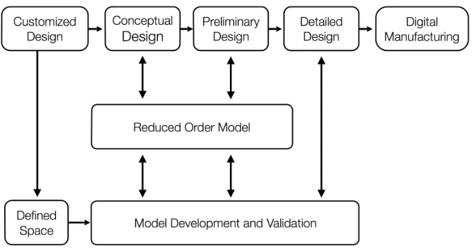
made. Altered workflow can be seen in Fig. 1. The design process begins with the goal of a customized design and the knowledge from previous design processes building the known design space. Two workflows are then simultaneously worked through; the first with a linear progression of concept refinement and the other developing the model depicting the design space. These two processes are coupled together using reduced order modeling such that the information is quickly shared between the workflows. Beginning in the conceptual phase a small number of snapshots are generated to provide the model with more information about the performance characteristics that this customized design will look to fulfill. The results from this group of snapshots are inaccurate for detailed design selection is critical in providing the ROM with a basis of the extremes for the design case. This information for the boundaries of the design space then informs the refinement of the design on the path toward detailed design. More snapshots are then generated as more cases are considered improving the accuracy of the reduced order model. At this point the ROM has obtained enough information about the design space the accurate predictions can begin to be made. The results from the use of the ROM in this phase can fully inform the designers for the final characteristics of the design such as geometry, and operational parameters such as rotational velocity or viscosity of the working fluid. From this information designers can choose a final design based on a set of already known characteristics, which the reduced order model has informed them of. Often in conventional workflow costly redesigns occur that require collaborators to return to the conceptual or preliminary design phases restarting a majority of the process again. The inclusion of reduced order models allow these stakeholders to make far-reaching design changes and know the results of these changes almost instantly.
IV.
Design Application
To implement this proposed design workflow, a case study was needed that could be adaptable for this research. The case study needed to have an already developed and manufactured design using conventional engineering design workflows. An existing design used in this research is the impeller.55 The design uses novel
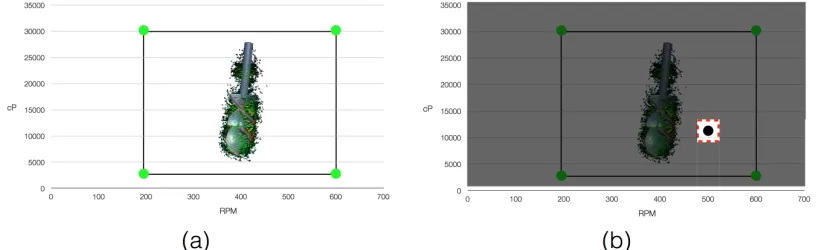
[image:7.612.140.484.325.506.2]mixing blade placements and impeller sizes to reduce the amount of time need to mix substances within a laboratory. These impellers though mixed fluids in significantly less time and at a reduced amount of power compared to other commercially available mixing blades. Both experimental and computational models were created under a variety of mixing conditions and impeller geometries. The result of which resulted in a large data set from which snapshots were taken that constructed the ROM. The geometry of the impeller developed was shown to be effective in a large operational range seen in Fig 2a. But for this research the focus was shifted towards a customized design for a subset of mixing conditions, Fig. 2b, which resulted in improved performance utilizing the proposed design workflow. It was found that different blade configurations resulted in varying mixing results
depending on the fluid.56 Different geometric ratios of the mixing impeller were identified as having the largest
effect on the resultant mixing times. The one being the diameter of the impeller over the diameter of the fluid vessel (D/T). From Yu et al. it was found that a D/T ratio of around 0.6 results in the best performance characteristics for the entire range of operating conditions. These operating parameters or input conditions can be seen in Table 1 where a range of working fluid viscosities, the rotations per minute of the impeller, and these varying D/T ratios resulted in different flow fields and thus mixing times. The high fidelity models that were developed for the original design of the impeller were adapted for this research providing the design space to search for this customized design. The exploration of this design space using ROMs allows for the design of the mixing impeller to be tailored for a refined set of mixing conditions (RPM and viscosity) resulting in an increase in performance.
Previously in the design of the mixing impeller different geometries and correspondingly meshes were developed to accurately simulate impeller performance. Due to these varying mixing impeller geometries the meshes used to conduct these simulations correspondingly varied in size. In the past ROMs have been used to predict limited geometry changes of designs that could be defined by a single variable57 or an equation to describe a curve58
but the geometries in this research were too complicated to be defined by either method. Proper orthogonal decomposition requires that ever snapshot inputted have exactly the same number of nodes in the mesh. To overcome this the information from the original simulations was interpolated onto these new modified meshes. The L2 norm of the flow field between the original and new mesh was 0.5%.
V.
Discussion of Results
The process of integrating detailed analysis into the conceptual and preliminary design phases began with validating ROMs against simulation and experimental data to determine their accuracy. Without an acceptable accuracy there is little chance that designers would want quick yet inaccurate simulations as opposed to time consuming accurate simulations. The outputs of a ROM are based upon its predictions for a queried set of parameters. In this research the parameters used were the rotations per minute of the mixing impeller and the viscosity of the working fluid which previously been shown to have the largest effect on the mixing times of the mixing impeller from the experimental research by Yu et al.56 The outputs of the ROM can be any property of the
[image:8.612.96.506.200.325.2]CFD simulations used to construct the ROM and for this research velocities in the x, y, and z directions along with magnitude are investigated and used for comparison. The total time each fluid took to be mixed under each scenario of viscosity, RPM and D/T ratio was inputted to the ROM. Using time the design space could now be used to search for an improved design that resulted in a lower mixing time given these other defining parameters.
Table 1. Operating conditions ranges of the mixing impeller for the case study.
Minimum Maximum
Viscosity (cP) 5,000 30,000
RPM 200 600
D/T 0.33 0.85
These parameters are chosen to inform the ROM for under what conditions does a snapshot’s flow field result. The Dow Chemical Company provided a collection of simulated mixing results for a wide range of mixing conditions within the designs operational range. Using these snapshots a ROM was constructed using the five most extreme operating conditions that defined the design space. It was important to be able to explore the design space fully and understand how many snapshots were needed for an accurate prediction. It was important to investigate areas within the flow field and compare the velocity profiles of varying planes for the ROMs of different sizes and the test case. The speed at which these results were obtained was a matter of seconds allowing the design space to quickly and accurately searched.
Mixing time was the most important since the goal of the designs was to reduce mixing times over other mixing impellers. For this research mixing time is t95, which is the time required for the solution to become 95%
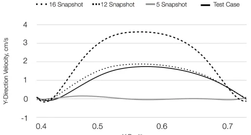
[image:9.612.179.443.337.474.2]mixed. The snapshots defined by the mixing time and D/T. These two parameters were chosen because the purpose of this research was to search the design space for geometries that further reduced mixing time. The construction of the ROM begins as the other with a few snapshots defining the design space with more snapshots added to improve the amount of knowledge about the design space. A progression in a reduction in the L2 norm, Table 2, occurs moving from 98% with five snapshots to 3% with sixteen snapshots. It is interesting to note that the reduction in L2 norm between five and twelve snapshots is minimal but in Fig. 3 and Fig. 4 it is seen that the y-velocity profile does change between the two with the snapshot ROM having similar profile to the test case but over shooting the magnitude. Using the mixing impeller as a case study different input and output parameters were investigated used to define and accurately predict results. With this information the design space was then searched for a customized design that would show improved performance for a refined set of operating conditions. The improved performance would be a further reduction in mixing time and the customized design would be a D/T ratio that differed from the
Fig. 3. Y-velocity profile of a reduced order model using mixing time for a varied geometry vs. the test case.
[image:9.612.178.436.526.665.2]known optimum for the entire design space. The ROM enables the researchers to quickly explore the design space. Due to this speed a large number of designs were considered. One design was found that accomplished this goal. A D/T ratio of 0.57 was identified to have 7-8% improvement in mixing time for RPMs under 300 and working fluid viscosities under 10,000 cp. So for the small subset of the design space an improved customized geometry was identified and confirmed using high fidelity modeling. Using this design it could quickly be made using digital manufacturing for an instant performance improvement. The power that coupling reduced order modeling and digital manufacturing is illustrated in this research by how simple it was identifying a design in an inexpensive and reduced timeframe.
VI.
Conclusion
This research developed a new method that amplified the power of digital manufacturing. Using this design workflow developed to take advantage of the benefits of digital manufacturing, customized products can be manufactured at little to no cost in a reduced timeframe. This level of customization enables designers to develop products for a refined set of operating conditions that result in improved performance characteristics. The customization of a design for this refined set of parameters builds upon on already established designs such that a collection of high fidelity models already exist from the established design development. While manufacturing technologies have seen rapid advancement in capabilities, the design process workflows used to develop these products have not followed a similar path of advancement. As a result, the disparity in timescales between the design process and manufacturing continues to expand. The design workflow developed and implemented in this research overcomes these disparate timescales through the utilization of reduced order modeling. ROMs couple the information developed in the three phases of design along with the ever-improving model of the designs performance within its design space. Additionally, in this implemented design workflow much of the high fidelity modeling is shifted earlier in the design process from the detailed phase and into the conceptual and preliminary phases. The result of which is an improved model of the design space focusing on these customized conditions. ROMs are a powerful tool that allows designers to explore the design space at timescales orders of magnitude less that that of high fidelity modeling. One aspect that had previously limited the power of ROMs was their ability to accurately predict the flow fields from complex geometry changes. The development of the universal mesh in this research overcomes this hurdle allowing for a new dimension of the design to be explored and not limited to operating conditions such as rotational velocity or fluid viscosity. A design case study using the Kar Dynamic Mixer was then used to implement the proposed design workflow. The ROM accurately predicted the flow fields for a variety of mixing conditions under various geometries. Because the mixing impeller had been previously been developed, a large amount of high fidelity models already existed limiting the amount of additional high fidelity simulations needed to develop the customized design. This reuse of these expensive and time-consuming high fidelity models amplifies their value. These models are then used to construct the ROM defining the design space for which collaborators can query for this customized design. The ease at which the design space was explored allowed for varying geometries to be investigated for certain mixing conditions. One example was found the for a customized geometry for a refined set of mixing conditions resulted in a 7-8% reduction in mixing time, a critical indicator of impeller performance.
Table 2. The L2 norm resultant of the number of snapshots used to construct reduced order models using mixing time for the mixing impeller for varied D/T ratios.
Number of Snapshots L2 Norm
5 98.1 %
12 90.2%
[image:10.612.80.523.219.269.2]References
1Berman, B. “3-D Printing: The New Industrial Revolution,” Business Horizons, Vol. 55, No. 2, 2012, pp.
155-162.
2Oden, J. T., Belytschko, T., Fish, J., Hughes, T. J. R., Johnson, C., Keyes, D., et al. “Simulation Based
Engineering Science Revolutionizing Engineering Science through Simulation,” National Science Foundation, 2006.
3Ertas, A., and Jones, J. C., The Engineering Design Process. Wiley, New York, 1993, pp. 3.
4Pahl, G., Beitz, W., Feldhusen, J., and Grote, K. H., Engineering Design: A Systematic Approach. 3rd ed. Edited
by Wallace, K., and Blessing, L., Springer, Berlin, 2007, pp. 130.
5Pivkin, I. V., Swartz, S., and Laidlaw, D. H., “Visualization and Interpretation of the Proper Orthogonal
Decomposition of Bat Wing Kinematics,” Thesis, Brown Univ, Providence, RI, 2006.
6McCorkle, D. S., Bryden, K. M., and Carmichael, C.G., “A New Methodology for Evolutionary Optimization of
Energy Systems,” Computer Methods in Applied Mechanics and Engineering, Vol. 192, No. 44, 2003, pp.
5021-5036.
7Meng, Q., Wang, C., Chen, Y., and Chen, J., “A Simplified CFD Model for Air-Lift Artificial
Upwelling,” Ocean Engineering, Vol. 72, 2013, pp. 267-276.
8Bourguet, R., Braza, M., and Dervieux, A., “Reduced-Order Modeling of Transonic Flows Around an Airfoil
Submitted to Small Deformations,” Journal of Computational Physics, Vol. 230, No. 1, 2011, pp. 159-184.
9Muld, T. W., Efraimsson, G., and Henningson, D. S., “Flow Structures Around a High-Speed Train Extracted
Using Proper Orthogonal Decomposition and Dynamic Mode Decomposition,” Computational Fluids
,"
Vol. 57,2012, pp. 87-97.
10Gibson, I., Rosen, D.W., and Stucker, B., Additive Manufacturing Technologies: Rapid Prototyping to Direct
Digital Manufacturing. Springer, Berlin, 2010, pp. 365.
11Horn, T. J., and Harrysson, O. L. A., “Overview of Current Additive Manufacturing Technologies and Selected
Applications,” Science Progress, Vol. 95, No. 3, 2012, pp. 255-282.
12Khalyfa, A., Vogt, S., Weisser, J., Grimm, G., Rechtenbach, A., Meyer, W., and Schnabelrauch, M.,
“Development of a New Calcium Phosphate Powder-Binder System for the 3D Printing of Patient Specific
Implants,” Journal of Material Science: Materials in Medicine, Vol. 18, No. 5, 2007, pp. 909-916.
13Melican, M. C., Zimmerman, M. C., Dhillon, M. S., Ponnambalam, A. R., Curodeau, A., and Parsons, J. R.,
“Three‐Dimensional Printing and Porous Metallic Surfaces: A New Orthopedic Application,” Journal of Biomedical
Materials Research, Vol. 55, No. 2, 2000, pp. 194-202.
14Liu, Y., Zhang, L., Zhou, G., Li, Q., Liu, W., Yu, Z., and Cao, Y., “In Vitro Engineering of Human Ear-Shaped
Cartilage Assisted with CAD/CAM Technology,” Biomaterials, Vol. 31, No. 8, 2010, pp. 176-183.
15Melchels, F. P., Domingos, M. A., Klein, T. J., Malda, J., Bartolo, P. J., and Hutmacher, D. W., “Additive
Manufacturing of Tissues and Organs,” Progress in Polymer Science, Vol. 37, No. .8, 2012, pp. 1079-1104.
16Li, L., and Liu, J., “An Efficient and Flexible Web Services-based Multidisciplinary Design Optimisation
Framework for Complex Engineering Systems,” Enterprise Information Systems, Vol. 6, No. 3, 2012, pp. 345-371.
17Catalano, C., E., Camossi, E., Ferrandes, R., Cheutet, V., and Sevilmis, N., “A Product Design Ontology for
Enhancing Shape Processing in Design Workflows,” Journal of Intelligent Manufacturing, Vol. 20, No. 5, 2009, pp.
553-567.
18Roldán, M. L., Gonnet, S., and Leone, H., “TracED: A Tool for Capturing and Tracing Engineering Design
Processes,” Advances in Engineering Software, Vol. 41, No. 9, 2010, pp. 1087-1109.
19Nagel, R. L., Hutcheson, R., McAdams, D. A., and Stone, R., “Process and Event Modelling for Conceptual
Design. Journal of Engineering Design, Vol. 22, No. 3, 2011, pp. 145-164.
20Yu, J., Cha, J., Lu, Y., Xu, W., and Sobolewski, M., “A CAE-Integrated Distributed Collaborative Design
System for Finite Element Analysis of Complex Product Based on SOOA,” Advances in Engineering Software, Vol.
41, No. 4, 2010, pp. 590-603.
21Alexopoulos, K., Makris, S., Xanthakis, V., and Chryssolouris, G. “A Web-Services Oriented Workflow
Management System for Integrated Digital Production Engineering,” CIRP Journal of Manufacturing Science and Technology, Vol. 4 No. 3, 2011, pp. 290-295.
22Weng, W. C., “Web-Based Post-Processing Visualization System for Finite Element Analysis,” Advances in
Engineering Software, Vol. 42, No .6, 2011, pp. 398-407.
23Lwin, T., Anh, N., Lee, J. W., and Kim, S., “A Distributed Web-Based Framework for Helicopter Rotor Blade
24McIntosh, P., Subic, A., Lee, K. W., Clifton, P., Trivailo, P., and Leary, M., “An Adaptable Virtual
Engineering Platform for Distributed Design Based on Open Source Game Technology,” Advances in Engineering
Software, Vol. 43, No. 1, 2012, pp. 71-86.
25Ari, I., and Muhtaroglu, N., "Design and Implementation of a Cloud Computing Service for Finite Element
Analysis," Advances in Engineering Software, Vol. 60-61, 2012, pp. 122-135.
26Valilai, O. F., Houshmand, M., “A Collaborative and Integrated Platform to Support Distributed Manufacturing
System using a Service-Oriented Approach Based on Cloud Computing Paradigm,” Robotics and Computer
Integrated Manufacturing, Vol. 29, No .1, 2013, pp. 110-127.
27Kurtoglu, T., Swantner, T., and Campbell, M. I., “Automating the Conceptual Design Process: From Black Box
to Component Selection,” Artificial Intelligence for Engineering Design, Analysis and Manufacturing, Vol. 24, No.
1, 2010, pp. 553-572.
28Chen, Y., Liu, Z. L., and Xie, Y. B., “A Knowledge-Based Framework for Creative Conceptual Design of
Multi-Disciplinary Systems,” Computer Aided Design Vol. 44, No. 2, 2012, pp. 146-153.
29Iványi, P., A New Conceptual Design Tool for Cable-Membrane Structures,” Advances in Engineering
Software, Vol. 57, 2013, pp. 33-39.
30Pyl, L., Sitters, C. W. M., and De Wilde, W. P., “Design and Optimization of Roof Trusses Using
Morphological Indicators,” Advances in Engineering Software, Vol. 62-63, 2013, pp. 9-19.
31Svoboda, L., Novák, J., Kurilla, L., and Zeman, J., “A Framework for Integrated Design of Algorithmic
Architectural Forms,” Advances in Engeering Software, 2013, (In Press).
32Anand,"A.,"and"Wani"M."F.,""Product"Life8Cycle"Modeling"and"Evaluation"at"the"Conceptual"Design"Stage:"A"
Digraph"and"Matrix"Approach,""Journal(of(Mechanical(Design,"Vol."132,"2010,"pp."091010.
33Bohm, M. R., Haapala, K. R., Poppa, K., Stone, R. B., and Tumer, I. Y., “Integrating Life Cycle Assessment
into the Conceptual Phase of Design Using a Design Repository,” Journal of Mechanical Design, Vol. 132, 2010,
pp. 0910051-091005110.
34Liu, Y., Huang, H. Z., and Ling, D., “Reliability Prediction for Evolutionary Product in the Conceptual Design
Phase Using Neural Network-Based Fuzzy Synthetic Assessment,” International Journal of System Science, Vol.
44, No .3, 2012, pp. 545-555.
35Caprace, J. D., and Rigo, P., “A Real-Time Assessment of the Ship Design Complexity,” Computer Aided
Design, Vol. 44, No. 3, 2012, pp. 203-208.
36Cheng, M. Y., Tsai, H.C., and Sudjono, E., “Conceptual Cost Estimates Using Evolutionary Fuzzy Hybrid
Neural Network for Projects in Construction Industry,” Expert Systems with Applications, Vol. 37, No. 6, 2010, pp.
4224-4231.
37Lin, T., Lee, J.W., and Bohez, E. L. J., “New Integrated Model to Estimate the Manufacturing Cost and
Production System Performance at the Conceptual Design Stage of Helicopter Blade Assembly,” International
Journal of Production Research, Vol.50, No.24, 2012, pp. 7210-7228.
38Thompson, E., “Incorporation of Computational Fluid Dynamics into Flight Vehicle Preliminary
Design,” Ph.D. Dissertation, Univ. of Dayton, Dayton, OH, 2012.
39Tomac, M., and Eller, D., “From Geometry to CFD Grids—An Automated Approach for Conceptual Design,”
Progress in Aerospace Science, Vol. 47, No. 8, 2011, pp. 589-96.
40Tenne, Y., “A Computational Intelligence Algorithm for Simulation-Driven Optimization Problems,” Advances
in Engineering Software, Vol. 47, No. 1, 2012, pp. 62-71.
41Azamatov, A., Lee, J. W., and Byun, Y. H., "Comprehensive Aircraft Configuration Design Tool for Integrated
Product and Process Development," Advances in Engineering Software, No. 42, Vol. 1, 2011, pp. 35-49.
42Fang, F., Pain, C. C., Navon, I. M., Gorman, G. J., Piggott, M. D., Allison, P. A., et al., “A POD Reduced
Order Unstructured Mesh Ocean-Modelling Method for Moderate Reynolds Number Flows,” Ocean Modeling, Vol. 28, No. 1, 2009, pp. 127-136.
43Alonso, D., Velazquez, A., and Vega. J. M., "A Method to Generate Computationally Efficient Reduced Order
Models," Computer Methods in Applied Mechanics and Engineering, Vol.198, No. 33, 2009, pp. 2683-2691.
44Bache, E., Alonso, D., Velazquez, A., and Vega, J. M., “A Computationally Efficient Reduced Order Model to
Generate Multi-Parameter Fluid-Thermal Databases,” International Journal of Thermal Sciences, Vol. 52, 2012, pp.
145-153.
45Walton, S., Hassan, O., and Morgan, K., “Reduced Order Modelling for Unsteady Fluid Flow using Orthogonal
Decomposition and Radial Basis Functions,” Applied Mathematical Modeling, Vol. 37, No. 20-21, 2013, pp.
8930-8945.
46Knezevic, D. J., Ngoc-Cuong, N., and Patera, A. T., “Reduced Basis Approximation and a Posteriori Error
Science, Vol. 21, No. 7, 2011, 1415-1442.
47Ma, Z., Ahuja, S., Rowley, C. W., “Reduced-Order Models for Control of Fluids using the Eigensystem
Realization Algorithm,” Theoretical Computational Fluid Dynamics, Vol. 25, No. 1-4, 2011, pp. 233-47.
48Noorian, M. A., Firouz‐Abadi, R. D., and Haddadpour, H., “A Reduced Order Model for Liquid Sloshing in
Tanks with Flexible Baffles Using Boundary Element Method,” International Journal of Numerical Methods in
Engineering, Vol. 89, No. 13, 2012, pp. 1652-1664.
49Carlberg, K., and Farhat, C., “A Low‐Cost, Goal‐Oriented Compact Proper Orthogonal Decomposition’s Basis
for Model Reduction of Static Systems,” International Journal of Numerical Methods in Engineering Vol. 863,
2011, pp. 381-402.
50Samadiani, E., and Joshi, Y., “Reduced Order Thermal Modeling of Data Centers via Proper Orthogonal
Decomposition: A Review,” International Journal of Numerical Methods for Heat and Fluid Flow, Vol. 20, No .5,
2010, pp. 529-550.
51Suhr, B., and Rubeša, J., “Model Order Reduction via Proper Orthogonal Decomposition for a Lithium-ion
Cell,” COMPEL: The International Journal for Computation and Mathematics in Electrical and Electronic
Engineering, Vol. 32, No. 5, 2013, pp. 1735-1748.
52Xiao, M., Breitkopf, P., Coelho, R. F., Knopf-Lenoir, C., and Villon, P., “Enhanced POD Projection Basis with
Application to Shape Optimization of Car Engine Intake Port,” Structural and Multidisciplinary Optimization, Vol.
46, No. 1, 2012, pp. 129-36
53Kirby, M., Geometric Data Analysis, John Wiley and Sons, New York, 2001, pp. 69.
54Brenner, T. A., Fontenot, R. L., Cizmas, P. G. A., O’Brien, T. J., and Breault, R. W., “A Reduced-Order Model
for Heat Transfer in Multiphase Flow and Practical Aspects of the Proper Orthogonal Decomposition,” Computers
and Chemical Engineering, Vol. 43, 2012, pp. 68-80.
55Kar, K. K., Somasi, M., and Cope, R. F., Rotatable mixing device and dynamic mixing method. U.S. Patent
7,946,753. 24 May 2011.
56Yu, Z., Cope, RF., Kar, K. K., Even, R. C., and Guillaudeu, S. J., “Mixing Performance of the Novel Kar
Dynamic Mixer Impeller in Small Laboratory-Scale Systems,” Industrial and Engineering Chemistry Research, Vol.
51, No. 46, 2012, pp. 15282-15292.
57McCorkle, D. S., and Bryden, K. M., “An Exploratory Framework for Combining CFD Analysis and
Evolutionary Optimization into a Single Integrated Computational Environment,” ASME 2011 International Design
Engineering Technical Conference and Computers and Information in Engineering Conference, Washington, D. C.,
2011 August 28-31, pp. 1589-98.
58Suram, S., McCorkle, D. S., and Bryden, K. M., “Proper Orthogonal Decomposition-Based Reduced Order
Model of a Hydraulic Mixing Nozzle,” Proceedings of the 12th AIAA/ISSMO Multidisciplinary Analysis and