SF/SD 8035
System
200/410
Service Manual
1.l1li
1.
~
Basic Four
®The information contained herein is proprietary to and considered a trade secret of Management Assistance Inc.
All rights reserved. No part of this publication may be reproduced,
recorded or stored in a retrieval system, or transmitted, in any form or by any means, whether electronic, mechanical, photographic, or otherwi$e, without prior written permission of the Basic Four Information Systems
Division of Management Assistance Inc.
All Rights Reserved
BFISD 8035
Copyright © 1981 by Management Assistance Inc.
All specifications are subject to change without notice.
Basic Four and MAl are registered trademarks of Management Assistance Inc.
i'TlrJlea Irl lrle unnea \:)laIeS OT AmeriCa
CHAPTER 1
1.0 1 . 1 1 .1. 1 1 .1.2 1.1.3 1.1.4 1.1.5 1.2 1.3 1.3.1 1.3.2 1.3.3 1.3.4
CHAPTER 2
2.0 2.1 2.2 2.2.1 2.2.2 2.2.3 2.2.3.1 2.2.3.2 2.2.3.3 2.2.4 2.3 2.3.1 2.3.2 2.3.2.1 2.3.2.2 2.3.3 2.3.3.1 2.3.3.2 2.3.3.3 2.3.3.4 2.3.3.5 2.3.3.6
2.3.4 2.3.5 2.3.5.1 2.3.5.2 2.3.6 2.3.7
TABLE OF CONTENTS
Page
INTRODUCTION
P u rp 0 s e . . . . . I ! . . . 1-1
Physical Description (Table 1-1) . . . . . . 1-1
Processor (Model 1340/1345) . . . . . . . . 1-2
Disc Drive (Model 2400) . . . . . . . . 1-4
Video Display Terminal (Model 7250) . . . . . 1-5
Magnetic Tape Cartridge Drive (Model 6400) . . . 1-5
Matrix Printer (Model 3200) . . . . . . . . . 1-6
Operational Specifications (Table 1-2) . . . 1-7
Options . . . . . . . . . . 1-11
9-Track, 800 BPI, Reel-to-Reel Magnetic Tape Drive . 1-11
4 or 8 Channel Terminal Controller . . . . . . . 1-12
Binary Synchronous Communications Controller . . . 1-13
Parallel (Local) Printer Controller . . . . . 1-13
INSTALLATION
Introduction . . . 2-1
Unpacking Procedure . . . . . . . . . . 2-5
Preinstallation Checks . . . . . . . . 2-5
AC Power Requirements . . . . ! • • • • • 2-5
Power Receptacl es . . . . . . . . . 2-6
Environmental Requirements . . . . . . . 2-8
Temperature . . . . . . . . . . 2-8
Humidity . . . . . . . 2-8
Static . . . 2-8
Space Requirements . . . . . . . . . 2-9
System Installation . . . 2-9
Tools . . . . . . . . . 2-9
Releasing Disc Drive Locking Devices . . . . . . 2-9
Head Actuator Lock . . . . . . 2-11
Spindle Lock . . . 2-11
Switch Settings . . . . . . . . . . . . 2-11
Accessory PCB . . . 2-13
4- or 8-Way Controller PCB . . . 2-13
Memory PCB's . . . . . . 2-13
Disc Drive Interface PCB (P/N 24201A) . . . . . . . 2-13
Disc Drive PLOX PCB (P/N 24142) . . . 2-13
Video Display Termina1(s) . . . 2-15 Inter-Power Supply Resistance Check . . . 2-15
Power Supply Output Check . . . 2-17
CPU/Memory Power Supply . . . . . 2-17
Disc Drive Power Supply . . . 2-21
Cable Interconnection . . . . . . . 2-22
System Power-Up Check . . . 2-24
iv
CHAPTER 2
2.3.8 2.3.8.1 2.3.8.2 2.4 2.5 2.6 2.6.1 2.6.2 2.6.3 2.6.4 2.6.5 2.6.6 2.6.7 2.6.8
CHAPTER 3
3.0 3.1 3.1.1 3.1.2 3.1.3 3.1.4 3.1.5 3.2 3.2.1 3.2.2 3.2.3 3.2.4 3.2.5 3.2.6 3.2.6.1 3.2.6.2
3.3
CHAPTER 4
4.0 4.1 4.2 4.2.1
TABLE
OF
CONTENTS (continued)Page
INSTALLATION (continued)
Adjustments . . . . . . . . . . 2-24
Track Fo llowing Adj us tment . . . . . . 2 - 24
Tach Gain Adjustment . . . . . . . . . . . 2-26
System Check-Out . . . . . . . 2-28
System Controls and Indicators . . . . . 2-28
Operating Procedures . . . 2-30
Disc System Load . . . . . . . . 2-30
Alternate Disc Load . . . 2-31
Alternate Tape Load (From System Tape) . . . 2-31
Writing Prototype Sectors 1 thru 15 . . . . . 2-31
Formatting Disc . . . . . . . . . 2-31
Installing Operating System From Tape . . . 2-32
Updating System Software . . . . . . . 2-32
Creating Backup Tape . . . . . . . . 2-32
THEORY OF OPERATION
Introduction . . . . . . . . . . . . . . 3-1
Functional Description . . . . . . . 3-1
Processor (Model 1340/1345) . . . . . . . . . 3-1
Video Display Terminal (Model 7250) . . . 3-3
Disc Drive (Model 2400) . . . . . . . . . . . 3-3
Magnetic Tape Cartridge Drive (Model 6400) . . . 3-3
Matrix Printer (Model 3200) . . . 3-4
Processor Functional Description . . . 3-4
Central Processing Unit (Model 1340/1345) . . . 3-6
Main Memory . . . . . . . . 3-7
Disc Drive Controller . . . . . . . . 3-10
Magnetic Tape Cartridge Controller . . . 3-11
Acces sory PCB . . . . . . . . \. . . 3-13
Bus Structure . . . 3-14
Input/Output Channel Busses . . ~ . . . . . . . 3-14
Direct Memory Access (DMA) Channel Busses . . . 3-17 Software . . . . . . . . 3-17
MAINTENANCE
Introduction
.
. .
.
. .
Preventive MaintenanceCorrective Maintenance . . .
Special Tools and Test Equipment
. . . 4-1
CHAPTER 4
4.2.2 4.2.3 4.2.3.1 4.2.3.2 4.2.3.3 4.2.3.4
CHAPTER 5
5.0 5.1 5. 1. 1 5.2
CHAPTER 6
6.0
TABLE OF CONTENTS (continued)
Page
MAINTENANCE (continued)
Troubl eshooting Procedure . . . . . . . . . . . . 4- 2 Diagnostic Tests . . . 4-3
CPU and VDT Boot Checker Diagnostic . . 4-3
Machine Language Diagnostics . . . 4-3
Basic All Purpose Service System (BASS) Diagnostics . . 4-5 System Power-Up Check . . . 4-6
REMOVAL/REPLACEMENT PROCEDURES
Introduction . . . . . . . . 5-1 Model 2400 Disc Drive . . . 5-1 Removal/Replacement . . . . . . . . 5-1 Spare Parts List . . . . . . . . 5-3
REFERENCE DATA
Reference Data . . . 6-1
Figure
1-1 2-1 2-2 2-3 2-4 2-5 2-6 2-7
2-8 2-9 2-10 2-11 2-12 2-13 2-14 2-15 3-1 3-2 3-3 3-4 3-5 3-6 3-7 3-8 3-9
LIST OF ILLUSTRATIONS
Page
System 200/410 Typical Configuration . . . . · . . . . 1-3 · . . . . 2-7 Processor/Disc Drive 110 VAC Outlet Wiring . . . .
Peripheral 110 VAC Outlet Wiring . . . . Typical System Floor Plan . . . .
. . . . . 2-7
Disc Drive Components, Top View ... . . . Processor Card Cage Locations and PDU . . . . Baud Rate Switch Settings . . . . . . . Bytes/Sector Disc Drive Sectors/Track Switch Settings,
· . . . . 2-10 · . . . . 2-12 2-14 • • . . • 2 -15
PLOX PCB . . . . . . . . . . 2-16
Processor/Disc Drive Cabinet, Major Assemblies . . . 2-18 System Cables . . . . . . 2-19
Disc Drive Power Supply Connector Pin Designations . 2-21
Cable to Connector Orientation . . . . . . . . . . 2-24
Track Following Adjustment Waveform . . . 2-25
CPU PCB Sense Switch Settings . . . . . . . . . . 2-27
Tach Gain Adjustment Waveform . . . 2-28
Processor Front Panel Switches/Indicators . . . 2-30
System 200/410 Functional Block Diagram . . . . . . . . 3-2
Processor, Functional Block Diagram . . . . . . . 3-5
Memory Refresh Cycle Timing Diagram . . . . . . . . . 3-7
Memory Write Cycle Timing Diagram .. . . 3-9
Memory Read Cycle Timing Diagram . . . 3-9
Simplified Firmware Flowchart, Disc Drive Controller . . 3-12
I/O Character Data Transfer Timing Diagram . . . 3-16
Block-of-Character I/O Timing Diagram . . . . . . 3-16
Table
1-1 1-2 2-1 2-2 2-3 2-4 2-5 2-6 2-7 2-8 3-1 3-2 4-1 4-2
LIST OF TABLES
Physical Specifications . . . .
Operational Specifications . . . . . . . . .
Installation Summary/Checklist . . . .
Installation Specifications . . . . . . . . .
Inter-Power Supply Resistance Check . . . . . .
No-Load Power Supply Voltages . . . . . . . . .
Loaded Power Supply Voltages . . . .
Disc Drive Power Supply Voltages . . . .
Interface Cable Installation . . .
Processor/Disc Drive Controls and Indicators . . . .
64K Main Memory (2-32K Memory PCB's) Address Bit Functions
Control Bus Commands . . . .
Preventive Maintenance Summary Recommended BASS Diagnostics
Page
1-2 1-7 2-1 2-2 2-17 2-20 2-21 2-22 2-23 2-29 3-8 3-15 4-1 4-5
CHAPTER 1
INTRODUCTION
1.0 PURPOSE
This Service Manual is intended to aid the Service Representative in the installation
and maintenance of the Basic Four System 200/410 computer systems.
The System 200 and 410 are very similar in structure and operation, therefore, the
information contained in this Manual applies to both Systems unless specified
otherwise.
Detailed information for the Video Display Terminal, Printer, Disc Drive, and
Magnetic Tape Cartridge Drive (MTCD) will not be included in this Manual. For more
detailed information refer to the respective Service Manuals:
BFC Document Number
8019
8012
8005
8015
Equipment
Video Display Terminal Service Manual, Model 7250
Matrix Printer Service Manual, Model 3200
Disc Drive Service Manual, Model 2400
Magnetic Tape Cartridge Drive Service Manual, Model 6400
Additional technical information on the CPU may be found in the "Model 1300 Central
Processing Unit Technical Manual", BFC Document Number SM 1020.
These Service Manuals will be referenced within this document when applicable.
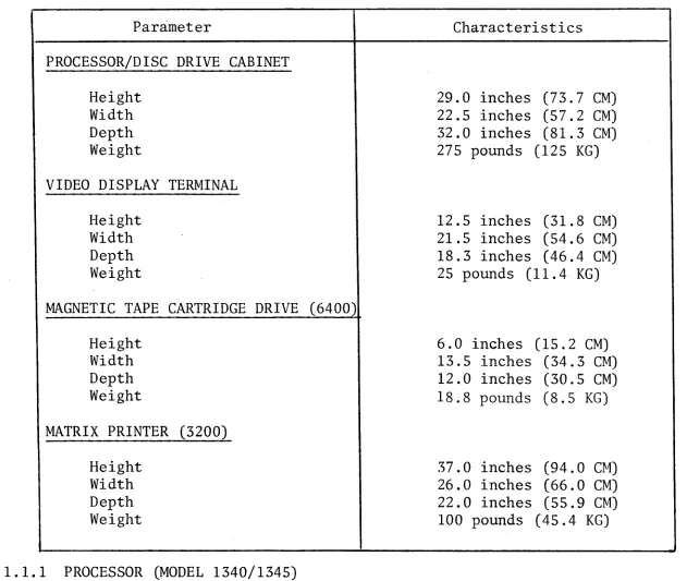
1.1 PHYSICAL DESCRIPTION (TABLE 1-1)
The System 200/410 consists of a Processor, Fixed Media Disc Drive, Video Display
Terminal(s), Printer(s), and Magnetic Tape Cartridge Drive (MTCD). Optional equipment
presently available include: 9 track reel-to-reel tape drive, various high speed
printers, binary synchronous communications, and additional video display terminals.
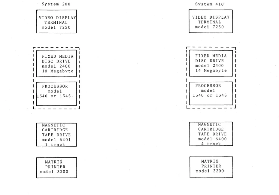
Both systems can be expanded by the addition of Printers and Video Display
Terminals (VDT) as well as increased Disc Drive and Main Memory capacity. Figure
1-1 illustrates the typical configuration for a System 200/410 computer.
TABLE 1-1. PHYSICAL SPECIFICATIONS
Parameter Characteristics
PROCESSOR/DISC DRIVE CABINET
Height Width Depth Weight
VIDEO DISPLAY TERMINAL
Height Width Depth Weight
MAGNETIC TAPE CARTRIDGE DRIVE (6400)
Height Width Depth Weight
MATRIX PRINTER (3200)
Height Width Depth Weight
1.1.1 PROCESSOR (MODEL 1340/1345)
29.0 inches (73.7 CM) 22.5 inches (57.2 CM) 32.0 inches (81.3 CM) 275 pounds (125 KG)
12.5 inches (31.8 CM) 21.5 inches (54.6 CM) 18.3 inches (46.4 CM) 25 pounds (11.4 KG)
6.0 inches (15.2 CM) 13.5 inches (34.3 CM) 12.0 inches (30.5 CM) 18.8 pounds (8.5 KG)
37.0 inches (94.0 CM) 26.0 inches (66.0 CM) 22.0 inches (55.9 CM) 100 pounds (45.4 KG)
The Processor is made up of a card cage and backplane which contains (at minimum)
the following PCBs:
1 - Central Processing Unit (CPU)
1 - 2 Channel Serial I/O (Accessory PCB)
1 or 2 Dynamic Semiconductor Memory
[image:10.816.87.718.213.746.2]f-I I (.N
System 200
VIDEO DISPLAY TERMINAL
model 7250
. - - - : - 1
I _ I
I FIXED MEDIA I
I DISC DRIVE
I model 2400
I
10 MegabyteII--_ _ - . _ _ ~
I .--_ _ _ _ _ _ ""'11
PROCESSOR
model 1340 or
1345-L _ _ _ _ _ _ _ _ J
MAGNETIC CARTRIDGE TAPE DRIVE
model 6401
MATRIX PRINTER
model 3200
System
410-VIDEO DISPLAY TERMINAL
model 7250
r - - - ,
I I
I FIXED MEDIA I
I DISC DRIVE I
I model 2400 I
I 14 Megabyte I
I I
I I
PROCESSOR I
model I
1340 or 1345
I
J
I
I
I
L _ _ _ _ _ _ _ _
J
MAGNETIC CARTRIDGE TAPE DRIVE
model-6400 4 track
MATRIX PRINTER
model 3200
[image:11.1057.65.994.59.708.2]1 - Magnetic Tape Cartridge Drive (MTCD) Controller
1 - CPU Power Supply
1 - Memory Power Supply
In addition, the Processor consists of a Power Distribution Unit (PDU), front panel
PCB, and battery.
The following optional PCBs may be present ln the Processor card cage.
1 - 4 or 8 Channel Serial I/O
1 - Binary Synchronous Communications Controller
1 or 2 High Speed Parallel Printer Controller
1 - 9 track Reel-to-Reel Magnetic Tape Drive Controller
The Processor is housed ln the lower half of the Processor/Disc Drive Cabinet
(see Figure 2-8).
Four, two position switches, located on the CPU PCB allow the selection of a
particular memory device (disc or tape) to be loaded into main memory.
Operator controls and indicators are mounted on the Processor/Disc Drive Cabinet
front door. The function of these controls and indicators are explained ln
Chapter 2.
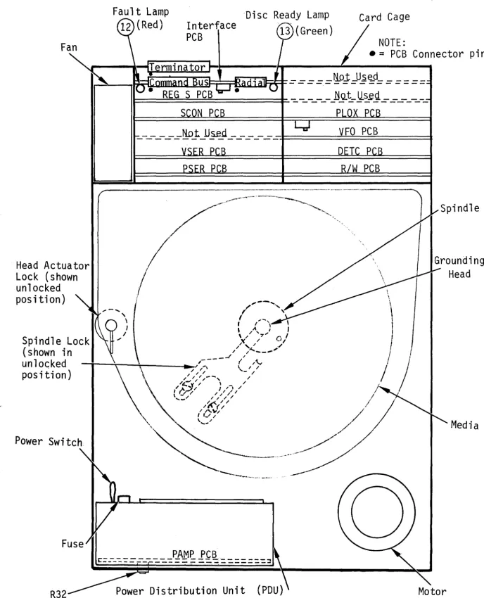
1.1.2 DISC DRIVE (MODEL 2400)
The Disc Drive Unit is located ln the upper portion of the Processor/Disc Drive
Cabinet (see Figure 2-8). The Disc Drive is a fixed media type, i.e., the discs
are not removable. The four (4) discs and head actuator are mounted on a metal
platform sealed ln a plastic housing. This sealed unit (referred to as the Deck
Plate Assembly) may only be opened at the factory when maintenance is necessary.
The Disc Drive card cage, which contains n1ne (9) PCBs, is mounted to the Deck
Plate Assembly. Access to these PCBs 1S gained by lifting off the Processor/Disc
Drive cabinet top cover.
The DC power is supplied from a physically separate power supply located behind
the Processor in the lower portion of the Processor/Disc Drive Cabinet (see Figure
2-8). The Disc Drive power supply AC input must be connected to the Processor PDU
to insure proper power on/off sequencing.
The Disc Drive 1S connected to a Disc Drive Controller PCB (located 1n the
Processor card cage) via two ribbon cables.
1.1.3 VIDEO DISPLAY TERMINAL (MODEL 7250)
The Video Display Terminal (VDT) is comprised of a standard typewriter keyboard,
10-key numeric keyboard, Cathode Ray Tube (CRT) display, and supplementary
electronic circuitry contained in a single enclosure.
Data communication between the VDT and Processor 1S by fUll-duplex asynchronous
communication lines which are directly connected V1a a cable or via telephone lines.
When directly connected, the VDT can be located up to 1,000 feet away from the
Processor.
1.1.4 MAGNETIC TAPE CARTRIDGE DRIVE (MODEL 6400)
The Magnetic Tape Cartridge Drive (MTCD) consists of a drive motor, four track
read/write/erase head, four (4) separate printed circuit boards, one (1) interconnect
board, and a power supply which are contained in a single enclosure. The MTCD
utilizes Basic Four Model 6903 tape cartridges with 1/4 inch wide tape.
The MTCD is connected to a Magnetic Tape Cartridge Drive Controller PCB (located In
the Processor card cage) by a single ribbon cable.
1.1.5 MATRIX PRINTER (MODEL 3200)
The Matrix Printer consists of a paper feed mechanism, print head mechanism,
internal control electronics, and a power supply which are contained in a single
enclosure. The Printer will accept forms up to 15 inches wide.
The Matrix Printer is supplied in two versions: Parallel interface (local
operation), and Serial interf~ce (remote operation). Both versions can operate
at speeds of 80, 120, or 160 characters per second. The Parallel interface
version is connected to a Printer Controller PCB located in the Processor card
cage. Interconnection is made via a ribbon cable. The Serial interface version
is directly connected to the Accessory PCB (or optional 4- or 8-Way Terminal
Controller) via a cable (1,000 feet maximum length) or connected by telephone lines
via modems.
Matrix Printer operator controls include: On/Off Line switch, Power switch, Test
switch, and Top of Forms switch.
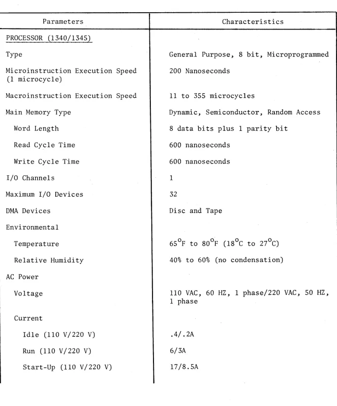
1.2 OPERATIONAL SPECIFICATIONS (TABLE 1-2)
TABLE 1-2. OPERATIONAL SPECIFICATIONS
Parameters Characteristics
PROCESSOR (1340/1345)
Type
Microinstruction Execution Speed (1 microcycle)
Macroinstruction Execution Speed
Main Memory Type
Word Length
Read Cycle Time
Write Cycle Time
I/O Channels
Maximum I/O Devices
DMA Devices
Environmental
Temperature
Relative Humidity
AC Power
Voltage
Current
Idle (110 V/220 V)
Run (110 V/220 V)
Start-Up (110 V/220 V)
General Purpose, 8 bit, Microprogrammed
200 Nanoseconds
11 to 355 microcycles
Dynamic, Semiconductor, Random Access
8 data bits plus 1 parity bit
600 nanoseconds
600 nanoseconds
1
32
Disc and Tape
40% to 60% (no condensation)
110 VAC, 60 HZ, 1 phase/220 VAC, 50 HZ, 1 phase
.4/.2A
6/3A
l7/8.5A
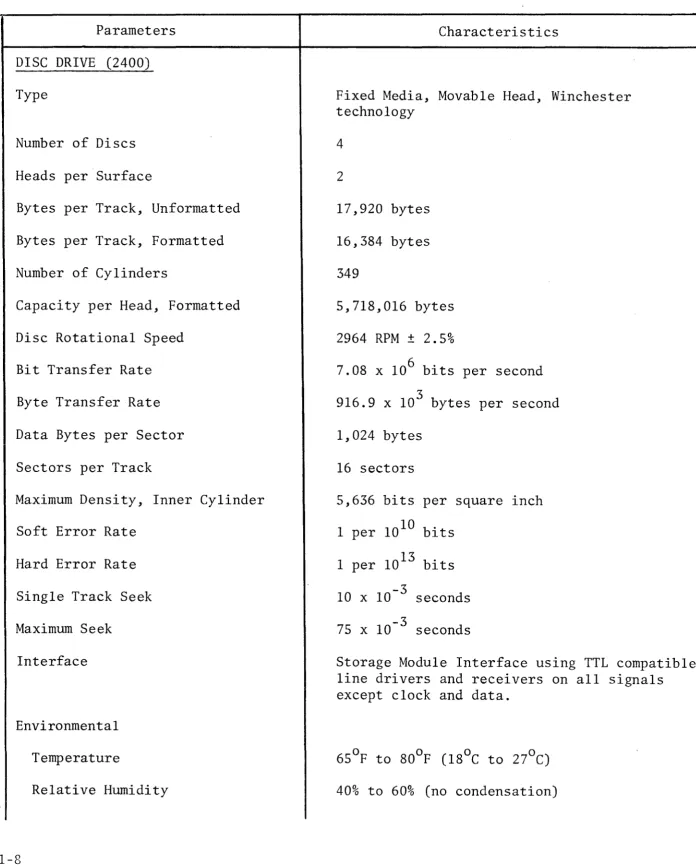
[image:15.816.69.730.143.940.2]TABLE 1-2. OPERATIONAL SPECIFICATIONS (continued)
Parameters Characteristics
DISC DRIVE (2400)
Type
Number of Discs
Heads per Surface
Bytes per Track, Unformatted
Bytes per Track, Formatted
Number of Cylinders
Capacity per Head, Formatted
Disc Rotational Speed
Bit Transfer Rate
Byte Transfer Rate
Data Bytes per Sector
Sectors per Track
Maximum Density, Inner Cylinder
Soft Error Rate
Hard Error Rate
Single Track Seek
Maximum Seek
Interface
Environmental
Temperature
Relative Humidity
1-8
Fixed Media, Movable Head, Winchester technology
4
2
17,920 bytes
16,384 bytes
349
5,718,016 bytes
2964 RPM ± 2.5%
7.08 x 106 bits per second
3
916.9 x 10 bytes per second
1,024 bytes
16 sectors
5,636 bits per square inch
1 per 1010 bits
1 per 1013 bits
10 x 10-3 seconds
75 x 10-3 seconds
Storage Module Interface using TTL compatible line drivers and receivers on all signals except clock and data.
[image:16.818.70.766.112.979.2]TABLE 1-2. OPERATIONAL SPECIFICATIONS (continued)
Parameters Characteristics
DISC DRIVE (2400)
AC Power Requirements
DC Power Requirements
+5.0 VDC
-5.2 VDC
+15.0 VDC
-15.0 VDC
MAGNETIC TAPE CARTRIDGE DRIVE (6400)
Type
Head
Recording Density
Tape Spe'd
Data Transfer Rate
Interface
Tape Cartridge
Tape Length
Tape Width
Storage Capacity
Environmental
Temperature
Relative Humidity
110 VAC, 60 HZ, 1 phase 220 VAC, 50 HZ, 1 phase
6.5A
4.0A
4.0A
4.0A
Magnetic Tape, Cartridge
1 or 4 track, dual gap (read/write/erase)
6400 bits per inch (4 track version)
30 inches per second (Read/Write)
90 inches per second (Fast Forward, Reverse, Search, and Rewind)
3
24 x 10 bytes per second (nominal)
TTL compatible, line drivers and receivers
300 feet (91.4 M)
0.25 inch (0.64 CM)
11.5 x 106 bytes (unformatted) (4 track version)
40% to 60% (no condensation)
TABLE 1-2. OPERATIONAL SPECIFICATIONS (continued)
Parameters Characteristics
MAGNETIC TAPE CARTRIDGE DRIVE (6400)
AC Power Requirements
DC Power Requirements
+24 VDC
-24 VDC
+5 VDC
MATRIX PRINTER (3200)
Type
Printer Speed
Form Thickness
Form Width
Line Feed Rate
Vertical Slew Rate
Interface
Environmental
Temperature
Relative Humidity
AC Power Requirements
1-10
110 VAC, 60 HZ, 1 phase, 1.SA 220 VAC, 50 HZ, 1 phase, 0.7SA
1.SA (typical), 3.4A (maximum)
1.9A (typical), 3.SA (maximum)
1.4A (typical), 2.6A (maximum)
9 x 7 dot matrix, impact
SO, 120, or 160 characters per second
0.040 inch (maximum)
4 inches to 15 inches (10.2 eM to 3S.l CM)
'-3
60 x 10 seconds per line feed
3.5 inches per second
Serial, RS-232C, f11ll duplex, asynchronous Parallel, TTL compatible line drivers and recelvers
40% to 60% (no condensation)
TABLE 1-2. OPERATIONAL SPECIFICATIONS (continued)
Parameters Characteristics
VIDEO DISPLAY TERMINAL (7250)
Type Cathode Ray Tube, electro-mechanical keyboard
Usable Screen Area
Screen Size
Horizontal Resolution
Keyboard
Character Format
Character Size
Interface
Data Transmission Speed
Environmental
Temperature
Relative Humidity
AC Power Requirements
1.3 OPTIONS
6.7 x 90 inches (17.02 x 228.6 CM)
12.0 inches (diagonal)
Center - 900 TV lines at 40 feet Corners - 750 TV lines at 40 feet
Standard typewriter (upper case letters only) Standard 10 key adding machine
Special control keys
5 x 7 dot matrix
0.119 inch high x 0.082 inch wide
Serial, RS-232C, full duplex, asynchronous
9600 or 2400 baud (standard)
40% to 60% (no condensation)
110 VAC, 60 HZ, 1 phase, 1.lA 220 VAC, 50 HZ, 1 phase, .55A
The following paragraphs briefly describe the options presently available for the
System 200/410.
1.3.1 9-TRACK, 800 BPI, REEL-TO-REEL MAGNETIC TAPE DRIVE
The Reel-to-Reel Magnetic Tape Drive provides a means of storing large quantities
of data. These tape units can be used in applications where the shorter data
access time of the disc memory 1S not needed.
The Reel-to-Reel Magnetic Tape Drive requlres a special Tape Drive I/O Controller
located in the Processor card cage. The following is a list of specifications
for the Reel-to-Reel Tape Drive.
•
Recording Mode•
Data Density•
Tape Velocity•
Data Transfer Rate•
Rewind Velocity•
Compatibility• Tape
• Reel Size
9-track, NRZI
800 bits per inch
12.5 inches per second
2,500 to 10,000 characters per second
50 inches per second
9-track (ASCII) or 7-track industry compatible format
Computer grade, 0.5 inch wide, 1.5 mil thick
7 inch diameter, IBM hub
1.3.2 4 OR 8 CHANNEL TERMINAL CONTROLLER
The 4 or
B
Channel Terminal Controller option allows up to four (4) or eight (8)serial type VDTs and/or printers to be tied to the System. The 4 or 8 Channel
Terminal Controller is located in the Processor card cage. Each channel utilizes
the standard RS-232C interface. The following lists the specifications for the 4
or 8 Channel Terminal Controller.
•
Data Format•
Bit Rate•
Sync Codes•
VRC/LRC/CRC•
Line Modes• Line Control
• I/O Bus Modes
• Interrupts
• Modern Interface
• Power Requirements
5, 6, 7, or 8 bits
9600 baud (maximum)
Programmable
Programmable
Synchronous, full or half uuplex, independent
transmit, and receive circv~ts
Auto-answer and line turn-around r
Programmed or concurrent data transfer
Data service, line conditions, and synchronization
RS-232C
+5 V, 1.BA
1.3.3 BINARY SYNCHRONOUS COMMUNICATIONS CONTROLLER
The Binary Synchronous Communications Controller (BSC) 1S a modem interface that
allows BSC over full and half duplex data links. The BSC Controller allows data
transmission rates from 200 to 20,000 baud. The BSC Controller 1S a single plug-in
board mounted in the processor card cage (see Figure 2-5). The BSC Controller has a
single channel which utilizes an 8 bit character encoded in EBCDIC (transparent or
non-transparent) character code assignments. All data is transmitted as a serial
bit stream. Automatic answer is a standard feature. The following lists the
specifications for the BSC Controller.
•
Modem Rates 20,000 bits/second max 1 mum•
Modem Interface RS-232C half and full duplex•
Transmission Codes EBCDIC or Transparent EBCDIC.,
Data Link Discipline IBM Binary Synchronous Communication•
Synchronization Modem supplied clock1.3.4 PARALLEL (LOCAL) PRINTER CONTROLLER
This option allows an additional high or medium speed Parallel Interface Printer to
be tied to the System 200/410. Parallel Printers cannot be located more than
30 feet from the Processor as cable lengths must be restricted.
The Parallel Printer Controller is located in the Processor card cage (see Figure
2-5). The Controller provides two separate interfaces, although only one may be
on-line with the system. One interface (connector P2) is used with Basic Four's
High Speed Printers (e.g., Model 3600), the other interface (connector P3) is used
with Basic Four's Medium Speed Printers (e.g., Model 3100, 3200, 3510). The
following lists the specifications for the Parallel Printer Controller.
• Number of Columns (characters)
per Print Line
Medium Speed Printer
High Speed Printer
Up to 132 characters per line of print
Up to 132 characters per line of print
• Maximum Output Data Rate
Medium Speed Printer
High Speed Printer
• Input Power Requirements
• Environmental
Temperature
Relative Humidity
• Circuit Types
132 characters per second (150 or 300 lines per minute)
300 or 600 lines per minute
+5 VDC, 1.SA from CPU (supplied via connector PIon circuit board)
40% to 60% (no condensation)
CHAPTER 2
INSTALLATION
2.0 INTRODUCTION
A summary/checklist of the major System 200/410 installation tasks are arranged in
the proper order of performance as shown in Table 2~1. Reference the section listed
in the table for details regarding each task. A summary of installation
specifications is contained in Table 2-2.
TABLE 2-1. INSTALLATION Sllf''!MARY /CHECKLIST
Step # Description of Task Reference Section
1 Unpack shipping containers, check inventory and damage 2.1
2 Verify customer AC power 2.2.1, 2.2.2
3 Verify customer environment 2.2.3, 2.2.4
4 Release Disc Drive locking devices 2.3.2
5 Verify system switch settings 2.3.3
6 Check inter-power supply resistances 2.3.4
7 Check DC power supply outputs 2.3.5
8 Install/verify cables 2.3.6
9 Perform system power-up check 4.2.3.4
10 Adjust/verify Disc Drive 2.3.8
11 Verify System configuration 2.4
12 Run diagnostics 4.2.3
TABLE 2-2. INSTALLATION SPECIFICATIONS
Parameters Characteristics
PROCESSOR/DISC DRIVE CABINET
Dimensions
Width Depth Height Weight
Service Clearances
Front Rear Sides
Electrical
Voltage Frequency Current
Environment
Temperature Humidity
Cable Lengths
Power Signal
VIDEO DISPLAY TERMINAL (VDT)
Dimensions
Width Depth Height Weight
Service Clearances
Front Rear Sides
Electrical
Voltage Frequency Current
22.4 inches (56.9 CM) 32.0 inches (Sl.3 CM) 29.0 inches (73.7 CM) 275 pounds (124.7 KG)
36.0 inches (91.4 CM) 30.0 inches (76.2 CM) lS.0 inches (45.7 CM)
115/230 VAC 60/50 HZ 10.5/5.25A*
65°F to SOoF (lSoC to 27°C) 40% to 60% (no condensation)
9 feet (2. 7 M) N/A
lS.3 inches (46.4 CM) 21.5 inches (54.6 CM) 12.5 inches (3l.S CM) 25 pounds (11.3 KG)
36.0 inches (91.4 CM) 12.0 inches (30.5 CM) 6.0 inches (15.2 CM)
TABLE 2-2. INSTALLATION SPECIFICATIONS (continued)
Parameters Characteristics
VIDEO DISPLAY TERMINAL (VDT)
Environment
Temperature Humidity
Cable Lengths
Power Signal
MATRIX PRINTER
Dimensions
Width Depth
Height (with stand) Weight
Service Clearances
Pront Rear Sides
Electrical
Voltage Frequency Current
Environment
Temperature Humidity
Cable Lengths
Power Signal
650p to SOop (lSoC to 27°C) 40% to 60% (no condensation)
S feet (2.4 M)
1000 feet maximum (304.S M)
26.0 inches (66.0 CM) 22.0 inches (55.9 CM) 37.0 inches (94.0 CM) 100 pounds (45.4 KG)
36.0 inches (91.4 CM) 30.0 inches (76.2 CM) lS.O inches (45.7 CM)
115/230 VAC 60/50 HZ 1.7S/,SSA
6SOp to Soop (lSoC to 27°C) 40% to 60% (no condensation,
S feet (2.4 M)
·1000 feet max. (304.S M) (serial interface only)
15 feet (4.6 M)
(parallel interface only)
TABLE 2-2. INSTALLATION SPECIFICATIONS (continued)
Parameters Characteristics
MAGNETIC TAPE CARTRIDGE DRIVE
Dimensions
Width Depth Height Weight
Electrical
Voltage Frequency Current
Environment
Temperature Humidity
Cable Lengths
Power Signal
WORK TABLE/DESK (OPTIONAL)
Dimensions
Width Depth Height Weight
200/410 SYSTEM
Electrical
Voltage Frequency Current Power
Heat Output
13.5 inches (34.3 CM) 12.0 inches (30.5 CM) 6.0 inches (15.2 CM) 16 pounds (7.3 KG)
115/230 VAC 60/50 HZ 1.5/0.75A
65°F to 80°F (18°C to 27°C) 40% to 60% (no condensation)
10 feet (3.1 CM) 6 feet (1. 8 eM)
36.0 inches (91.4 CM) 32.0 inches (81.3 CM) 29.0 inches (73.7 CM) 103 pounds (46.7 KG)
115/230 VAC 60/50 HZ
14.85/7.425A 1708 VA
2.1 UNPACKING PROCEDURE
The following is the recommended procedure to unpack the System 200/410 Processor
and peripherals from their shipping containers. All packages should be opened
immediately upon arrival and inventoried for completeness.
• Prior to opening the shipping containers, carefully inspect them for slgns
of damage that may have occurred in shipment. Any damage must be noted on
the carrier's shipping form. NOTIFY the Marketing Office of any shortage
or damage immediately so that corrective action can be taken.
• Carefully remove the Processor, Printer(s), MTCD, VDT(s), and cables from
their respective shipping containers. Save all shipping containers and
packing materials in the event that reshipment of the equipment lS required at a later date.
• Insure that the System is complete. Compare the items sent with the
Shipping List. If it is found that the system is incomplete, make a list
of the missing items and report it to your Marketing Office.
• Visually inspect all items for shipping damage. Pay particular attention
to inspect the cables and connectors for pinched wires and/or poor electrical
connections. Report any damaged parts to your Marketing Office.
• Remove the Processor/Disc Drive Cabinet top cover and remove the layer of
foam on the top of the Disc Drive. For reshipment, replace the layer of
foam on the top of the Disc Drive.
2.2 PREINSTALLATION CHECKS
2.2.1 AC POWER REQUIREMENTS
It is important that the System 200/410 receive proper ac power. Therefore, prlor
to selecting a location to install the system, check that:
• The ac power outlet(s) are the proper voltage (110 volts ac, 60 Hertz or
220 volts ac, 50 Hertz as applicable) and near enough to the equipment so that power extension cables are not necessary.
• The ac line is not subject to voltage variations greater than 10% or
frequency variations greater than 0.2%.
• The ac line is not shared by devices that cause large transients
(examples: air conditioners, heaters, welding equipment, and other
equipment with large motors) .
• The AC line can meet the following system current requirement:
Component
Processor/Disc Drive (single line)
Voltage
110 VAC
220·VAC
Current
lsA continuous
30A power-up surge for 15 seconds
7.sA continuous
lsA power-up for 15 seconds
Video Display Terminal 110 VAC 1.lA
Matrix Printer
Magnetic Tape Cartridge Drive
220 VAC 0.s6A
110 VAC s.OA
220 VAC 2.sA
110 VAC 1.sA
220 VAC .7sA
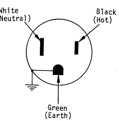
2.2.2 POWER RECEPTACLES
The 110 volts ac Processor/Disc Drive Cabinet requIres a Hubble 4710 power receptacle
(or equivalent twist-lock type receptacle) on a dedicated circuit breaker. The
Hubble 4710 power receptacle (or equivalent) must be wired as shown in Figure 2-1.
The VDT, Printer, and MTCD requIre a standard 2 pole, 3 wire ac out\et. The VDT,
Printer and MTCD may share a single circuit breaker of' the proper current rating.
White
(Neutral
).-~~Black
(Hot)
Green
(Earth)
Figure 2-1. Processor/Disc Drive 110 VAC Outlet Wiring
White
(Neutral)
Green
(Earth)
Figure 2-2. Peripheral 110 VAC Outlet Wiring
[image:29.816.241.503.170.435.2] [image:29.816.302.541.605.847.2]2.2.3 ENVIRONMENTAL REQUIREMENTS
2.2.3.1 Temperature
It is recommended that the System 200/410 be operated in a room where the ambient
temperature is between 650F to 800F (18oC to 27oC). The exhaust heat of the
System 200/410 is 5,808 BTU/Hour.
2.2.3.2 Humidity
It is recommended that the System 200/410 be operated in a room where the relative
humidity is maintained between 40% to 60% (non-condensating). High humidity can
cause printer paper handling problems. Low humidity can cause excessive static
charge build-up.
2.2.3.3 Static
It is recommended that static-free carpet be installed, or that the existing
carpeting be specially treated for this condition, or the system be installed
in an area without carpeting.
Static problems can be minimized by the installation of carpet containing Brunslon
fiber (avoid wool carpet). In cases of existing carpet, if it is not non-static,
it should be treated by spraying with a non-static fluid. The carpets should be
cleaned before spraying. The following is a list of some of the brands of non-static
fluids that are available:
AS/20 Anti-Static Agent
Wallerstein Company 6301 Lincoln
Morton Grove, Illinois
Bigelow Anti-Shock Spray
Bigelow-Sanford Inc. 140 Madison Avenue
New York City, New York
Carbona Stop-Shock
2.2.4 SPACE REQUIREMENTS
Consult with the customer to select a suitable location for the System 200/410.
There are no strict requirements as to where the computer may be installed, with
the exception of ac power (refer to Section 2.2.1). However, the following guidelines
will aid in selecting the most ideal location from both a maintenance and customer
usability point of view.
• Avoid areas where the operator will face into direct sunlight while
operating the VDT.
• Select an area that 1S central to the areas providing input to the computer.
• Select an area that allows the computer components to be spaced far enough
apart to allow access for maintenance (refer to Table 2-2).
A typical arrangement of the System 200/410 components is shown in Figure 2-3.
2.3 SYSTEM INSTALLATION
2.3.1 TOOLS
The following tools are required to perform the installation procedures contained
1n this document.
1 - Digital Multimeter, 3~ digit
1 - 10 Foot Measuring Tape
2 - Common Screwdriver
1 - Oscilloscope, Dual Trace
1 - Adjusting Tool, Slotted
2 - Disc Drive PCB Extender (MM2590l0)
2.3.2 RELEASING DISC DRIVE LOCKING DEVICES
NOTE
Prior to applying power to the Processor/Disc Drive Cabinet, it is important that these locking devices are released.
N
I I--'
o
~
Processor/
Disc Drive
~~1811~
I
MTcnl
I~
,--36"
REAR
I
Table
VDT
Printer
~181~ ~181~
120"
FRONT
Sca 1 e: 1/4" = 6"
2.3.2.1 Head Actuator Lock
Release the Disc Drive Head Actuator Lock (see Figure 2-4) by first remov1ng the
Processor/Disc Drive Cabinet top cover, then rotating the Head Actuator Lock
clockwise until the locking arm rests against the disc housing.
2.3.2.2 Spindle Lock
Release and reposition the Disc Drive Spindle Lock mechanism, located on the
. underside of the Disc Drive (see Figure 2-4), by loosening the two mounting screws
and sliding the locking plate outward until the grounding head rests centered on
the spindle. Retighten the two mounting screws.
2.3.3 SWITCH SETTINGS
Each serial device (VDT and Remote Printer) 1S assigned a terminal number as
specified by the operating system software. The remote printer(s) is always the
last teTminal.
Example: A System 410 with 4 VDT's and 1 remote printer is configured as follows:
VDT's are terminals 0 thru 3 and the remote printer is terminal 4.
The following lists the PCB-Connector for each terminal.
PCB-Connector Serial Device Assignment
Accessory PCB - J2 Terminal 0
Accessory PCB - J4 Terminal 1
4- or 8-Way PCB - J0 Terminal 2
4- or 8-Way PCB - Jl Terminal 3
4- or 8-Way PCB - J2 Terminal 4
4- or 8-Way PCB - J3 Terminal 5
8-Way PCB - J4 Terminal 6
8-Way PCB - J5 Terminal 7
8-Way PCB - J6 Terminal 8
8-Way PCB - J7 Terminal 9
Head Actua tor
Lock (shown
unlocked
position)
Spindle Lock
(shown in
unlocked
position)
Power Switch
R32
Fault Lamp
12
(Red)
Interface
PCB
Disc
Card Cage
NOTE:
.=
PCB Connector pin
1~L...,.~~~iiiai~~~~alIi~
=
=-
= =
=~oJ
_
U~~d=
==
= = =I=========::::::::::::============t=-
-=---
J~ Q..~ .!J.~d.
-= -= _-___ -_
P P
_~-~~-=~~~~d-=~-=~~_±=======V=F=O=P=C=B======~
DET
- - - _ . _ - - _ ..
_._
...._._--_._----_._----_._---PAMP PCB.
L=:_ -:. -=
= ..:-_-_ -:..
-=..:::=
= :;: ::. -
~::::.::
=
=::::. ~Grounding
Head
Media
Power Distribution Unit
Motor
Note: See Table 2-8 for description of numbered cal10uts (12 and 13)
[image:34.822.63.751.41.890.2]Prior to system power-up, verify that system switches are set on the following PCBs.
2.3.3.1 Accessory PCB
• Verify that the Processor Accessory PCB (see Figure 2-5) switch SWI (VDT
port baud rate) is set to the 9600 baud position (see Figure 2-6).
• Verify that the Processor Accessory PCB SW2 is set to the correct baud rate
for the device assigned (2400 for Serial Printer, 9600 for VDT) (see
Figure 2~6).
2.3.3.2 4- or 8-Way Controller PCB
Systems containing multiple VDTs and Serial Printers require a 4- or 8-Way Controller
PCB (see Figure 2-5). Set the baud rate switch for each channel to equal the
corresponding VDT or Serial Printer's specified baud rate. Switch settings are
shown in Figure 2-6.
2.3.3.3 Memory PCB's
Verify that the memory select switch (Sl) on each of the two memory PCB's is set so
that a contiguous block of memory is addressed beginning at location O. A chart 1S
printed on each memory module listing the switch settings.
2.3.3.4 Disc Drive Interface PCB (P/N 2420lA)
One, eight position switch controls the device address, read-only mode, and
diagnostic. Verify that the switch is set as follows; switch position 1 thru 3 = ON,
4 thru 7
=
OFF, 8=
ON. See Figure 2-4 for the location of the Interface PCB withinthe Disc Drive card cage. Remove the Processor/Disc Drive Cabinet top cover to gain
access to the Disc Drive card cage.
2.3.3.5 Disc Drive PLOX PCB (P/N 24142)
Three, eight position switches located on the Disc Drive PLOX PCB control the
bytes/sector (1118) and sectors/track (16). Verify that the switches are set as
shown in Figure 2-7. Remove the Processor/Disc Drive Cabinet top cover to gain
access to the Disc Drive card cage.
N
I
t--'
~
Power Distribution
unit/ (PDU)
Fan Power
Switch
Breaker
I !!e
Di sc Dri
ve
Power
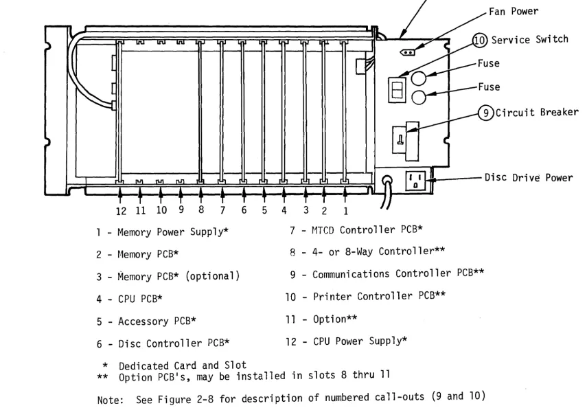
1 - Memory Power Supply*
2 - t·1emory PCB*
3 - Memory PCB* (optional)
4 - CPU PCB*
5 - Accessory PCB*
6 - Disc Controller PCB*
7 - MTCD Controller PCB*
8 - 4- or 8-Way Controller**
9 - Communications Controller PCB**
10 - Printer Controller PCB**
11 - Option**
12 - CPU Power Supp1y*
* Dedicated Card and Slot
** Option PCB's, may be installed in slots 8 thru 11
Note:
See Figure 2-8 for description of numbered call-outs (9 and 10)
[image:36.1067.79.935.67.661.2]~Off On~
To select a particular baud rate, set the corresponding
switch position to ON. Set
all other switch positions
to OFF. (switch shown is set
to 9600 baud)
Figure 2-6. Baud Rate Switch Settings
2.3.3.6 Video Display Terminal(s)
1
2
3
4
5
6
7
8
~ 9600 Baud
~4800 Baud
~ 2400 Baud
~1200 Baud
~600 Baud
~300 Bau.d
~150 Baud
~ 110 Baud
• Verify that the baud rate switch, located on the VDT rear panel 1S set to
9600 baud.
• Verify that the duplex switch, located on the VDT rear panel, 1S set to
F (full-duplex).
2.3.4 INTER-POWER SUPPLY RESISTANCE CHECK
To ensure that the Processor power supplies are· not short circuited, perform the following
procedure prior to applying power to the system.
2-16
A
B
c
I I
12
~
=
3 •
.
~
6.-=
7 •
8 •~
On Off
~I I I I
PLOX 24142
I I I I
1. Remove the Processor/Disc Drive Cabinet rear panel and extract all PCB's, except memory power supply and CPU power supply, from the card cage
backplane connectors. See Figure 2-5 to identify the location of each PCB.
2. With a multimeter, set to the R x 1 resistance range, check that short circuits do not exist between any of the power supply outputs as shown in Table 2-3. Test all possible combinations at the test points indicated in Table 2-3.
TABLE 2-3. INTER-POWER SUPPLY RESISTANCE CHECK
Test Point Signal
CPU PIS - TP3 +5V
CPU PIS - TPI +12V
CPU PIS - TP2 -15V
CPU PIS - TP4 Ground
Memory PIS - TP5 +5V Bkup
Memory PIS - TP4 +12V Bkup
Memory PIS - TP3 -5V Bkup
2.3.5 POWER SUPPLY OUTPUT CHECK
The Processor Service Switch and Circuit Breaker must be in the OFF position whenever a PCB or cable is inserted or extracted from a connector, otherwise hardware damage and/or program errors may result.
2.3.5.1 CPU/Memory Power Supply
1. Connect both battery wires to the battery; white wire to minus (-), black
wire to plus (+). The location of the battery within the Processor/Disc
Drive Cabinet is shown in Figure 2-8.
2. Install CPU PCB (P/N 903044) in card cage slot #4 (see Figure 2-5).
3. Connect the two front panel cables (10 conductor ribbon cable PIN 901662) as shown ln Figure 2-9.
4. Set Disc Drive Power Switch to the OFF position (see Figure 2-4).
N
,
t-'
(X)
Oisc Orive power
OistributiOn Unit (POU)
PY'ocessor
Card Cage
U1SC UY'i'le
Processor power Distribution
PCB
unit (PDU)
Figure 2-8. processor/Disc Drive Cabinet, Major Assemblies
DisC Drive
Card Cage
N
,
I--' toMinimum Configuration
Optional
• =
NOTE:
PCB Connector pin
1Front
Panel
Mem
PIS
903034
Memory
Memory
CPU
903044
AccessorYJ
903046
JitJ2=~t1TCD Cont.
903030
r:---,
'4/8Way Cont-I
1 1P2
I I
I
I~~iiit-:Conq
r"
~96
:901416
I
j
0,
-
-
-
-
-
--
-
--
--
-
-
...-
"~ ...
P3 ' - - - ... ....
CPU
PIS
903038
I i
a-,
- -- - - -, ... ,
I - - .,.., ... '-..A.'
tlfl J' I
"4>'~~
- ~~,
"P31 r-... ~
.1 I ~ , , '
,
...
... \
\ \
- - - \ \ - - - '"'7i
I ' - - -\ ,- - - - 7' )
I \ , I
f-
----
I _____ -{ I,-, 1_....,
II I , I I i I
LP
~ ra-:l ~ e": :..-P!
i n t~rJ/
Figure 2-9. System Cables
VDT
Disc Drive
r~agnet
i c Tape
Cartridge
Drive
5. Insert Processor/Disc Drive Cabinet line cord into designated wall outlet (refer to Section 2.2.1).
6. Set Processor Circuit Breaker to the ON position.
7. Set Processor Service Switch to the ON position.
8. Set Processor Front Panel Power Switch to the ON position.
9. Using a multimeter, set to the 20 volts dc range, verify measurements 1 thru 6 as listed in Table 2-4. Measure all voltages between Ground
(Memory Power Supply - TPI or CPU Power Supply - TP4).
TABLE 2-4. NO-LOAD POWER SUPPLY VOLTAGES
Measurement Test Point Location Voltage
1 CPU PIS - TP3 +4.75 V to +5.25 V
2 CPU PIS - TPI +11.4 V to +12.6 V
3 CPU PIS - TP2 -14.25 V to -15.75 V
4 MEMORY PIS - TP5 +4.75 V to +5.75 V (Bkup)
... -.-,,..,...--.. ~-,~-., ... -~-,-. --... ,,----"", ~--.. ,,~~ _ ... " ,,,. -... -.-.. ~- ... '--'-... __ ..
_--_._--5 MEMORY PIS - TP4 -4.75 V to -5.25 V (Bkup)
6 MEMORY PIS - TP3 +11.4 V to +12.6 V (Bkup)
10. Set Processor Front Panel Power Switch to OFF.
11. Verify presence of Back-up (Bkup) voltages, measurements 4 thru 6 as listed in Table 2-4.
12. Verify absence (i.e., 0 volts dc) of unprotected voltages, measurements 1 thru 3 as listed in Table 2-4.
13. Set Processor Service Switch to the OFF position.
14. Set Processor Circuit Breaker to the OFF position.
15. Install all PCB's in Processor card cage (see Figure 2-5).
16. Set Processor Circuit Breaker to the ON position.
17. Set Processor Service Switch to the ON position.
18. Set Processor Front Panel Power Switch to the ON position.
19. Using a multimeter, set to the 20 volts dc range, verify measurements 1 thru 6 as listed in Table 2-5. Measure all voltages between Ground
TABLE 2-5. LOADED POWER SUPPLY VOLTAGES
Measurement Test Point Location Voltage
1 CPU PIS - TP3 +4.75 V to +5.25 V
2 CPU PIS - TPI +11.4 V to +12.6 V
3 CPU PIS - TP2 -13.5 V to -16.5 V
-4 MEMORY PIS - TP5 +4.75 V to +5.25 V
5 MEMORY PIS - TP4 -4.75 V to -5.25 V
6 MEMORY PIS - TP3 +11.4 V to +12.6 V
2.3.5.2 Disc Drive Power Supply
1. The Disc Drive Power Supply is located directly behind the Processor/Disc Drive Cabinet front door (see Figure 2-8). The Disc Drive Power Supply.
is mounted on hinges that allow it to sWlng out.
2. Open the Processor/Disc Drive Cabinet front door, loosen the two
fasteners secllring the Disc Drive Power Supply, and swing the Power Supply out.
3. Remove connectors P30l and P303 from the Disc Drive Power Supply (see
Figure 2-10).
J301 J303
1 3 5 1 3 5 7
e
e e
e
e
e e
I I IT
e
e
e
e
e
e e
2 4 6 2 4 6 8
Figure 2-10. Disc Drive Power Supply Connector Pin Designations
4. Set the Disc Drive Power Switch to the ON position.
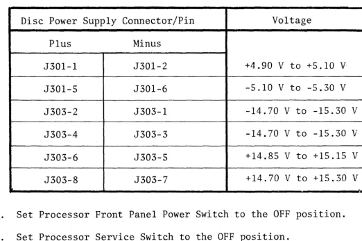
5. Using a multimeter, verify the dc voltages at the Disc Drive supply
connector pins listed in Table 2-6. The pin number designations on J30l
and J303 are shown in Figure 2-10.
[image:43.820.137.678.106.342.2]TABLE 2-6. DISC DRIVE POWER SUPPLY VOLTAGES
Disc Power Supply Connector/Pin Voltage
Plus Minus
J30l-l J30l-2 +4.90 V to +5.10 V
J30l-S J30l-6 -5.10 V to -5.30 V
J303-2 J303-l -14.70 V to -15.30 V
J303-4 J303-3 -14.70 V to -15.30 V
J303-6 J303-S +14.85 V to +15.15 V
J303-8 J303-7 +14.70 V to +15.30 V
6. Set Processor Front Panel Power Switch to the OFF position.
7. Set Processor Service Switch to the OFF position.
8. Set Processor Circuit Breaker to the OFF position.
9. Reconnect Disc Drive de power connectors P30l and P303 to the Disc Drive Power Supply.
2.3.6 CABLE INTERCONNECTION
Install/VerifY,system interface cables as described in the following procedure:
2-22
1. Position the System 200/410 components in the desired locations (refer to
Section 2.3).
2. Install all cables as listed in Table 2-7. The location of connectors
within the system are identified in Figure 2-9.
It is important that cables and connectors are properly identified and connected pin-to-pin prior to applying power to the Processor and associated peripherals, otherwise, hardware damage and/.or program errors may result.
[image:44.826.126.648.104.451.2]
1---,
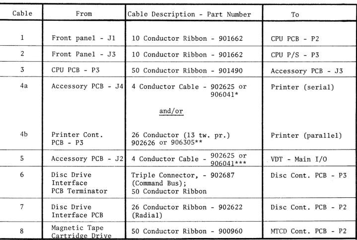
TABLE 2-7. INTERFACE CABLE INSTALLATION
Cable From Cable Description - Part Number To
1
2
3
4a
4b
5
6
7
8
NOTE:
*
**
***
Front panel - Jl 10 Conductor Ribbon - 901662 CPU PCB - P2
Front Panel - J3 10 Conductor Ribbon - 901662 CPU PIS - P3
CPU PCB - P3 50 Conductor Ribbon - 901490 Accessory PCB - J3
Accessory PCB - J4 4 Conductor Cable - 902625 or Printer (serial) 906041*
and/or
Printer Cont. 26 Conductor (13 two pr.) Printer (parallel)
PCB - P3 902626 or 906305**
Accessory PCB - J2 4 Conductor Cable - 902625 or . VDT - Main I/O 906041***
Disc Drive Triple Connector, - 902687 Disc Cont. PCB - P3
Interface (Command Bus);
PCB Terminator 50 Conductor Ribbon
Disc Drive 26 Conductor Ribbon - 902622 Disc Cont. PCB - P2
Interface PCB (Radial)
Magnetic Tape 50 Conductor Ribbon - 900960 MTCD Cont. PCB - P2
Cartridge Drive
Figure 2-9 identifies the location of connectors listed above.
Use with single Serial (remote) Printer
Use with Parallel (local) Printer
Additional VDT's/Serial Printer use 4- or 8-Way Controller PCB.
Connect Serial Printer to last terminal port (refer to Section 2.3.3).
[image:45.816.53.772.120.603.2]Contrasting stripe
Figure 2-11. Cable to Connector Orientation
2.3.7 SYSTEM POWER-UP CHECK
Perform the System Power-Up Check as described in Chapter 4, Section 4.2.3.4. The
System Power-Up Check presents a logical approach to verifying that the system 1S
operating properly and identifying common equipment problems encountered during
installation.
2.3.8 ADJUSTMENTS
2.3.8.1 Track Following Adjustment
It is recommended that Disc Drive Track Following circuitry be checked as outlined
1n this procedure when the system is installed. First, perform Track Following
Adjustment, then Tach Gain Adjustment (refer to Section 2.3.8.2).
2-24
CAUTION
Adjustment to the Track following circuitry
[image:46.824.138.680.65.430.2]1. Connect Oscilloscope Channel A to test point 16 on PSER PCB.
2. Install Disc Drive PCB extender (MM#2590l0) to Disc Drive VSER PCB (see
Figure 2-4).
3. Connect Oscilloscope Channel B to VSER PCB, connector pin R2.
4. Set Oscilloscope Trigger Source to Channel A, minus (-) slope.
5. Set Processor Front Panel Power switch to ON.
6. Observe that Disc Ready lamp (see Figure 2-4) IS illuminated.
7. Observe Oscilloscope Channel A and verify peaks Band C (see Figure 2-12)
are of equal amplitude.
8. If peaks Band C are not of equal amplitude, adjust R32 on PAMP PCB only if a Zero Recovery Tape is readily available.
9. Observe O£cilloscope Channel B and verify that zero volts ±0.5 volts level is present.
10. If R32 on PAMP PCB was adjusted, perform the following operations:
a. Zero Recovery Procedure
b. Write Prototype Sectors 1 thru IS (refer to Section 2.6.4)
c. Format Disc (refer to Section 2.6.5)
d. Install System Software (refer to Section 2.6.6)
B
C
~ J r \
~
V ,
J
~
~
\
,
[
L
~
,
/
A
~Figure 2-12. Track Following Adjustment Waveform
Equal
Amplitude
[image:47.832.197.693.608.907.2]2.3.8.2 Tach Gain Adjustment
It is recommended that the Disc Drive Tach Gain be adjusted when the system is
installed. The Tach Gain is adjusted such, that the average time to complete a
seek between cylinders 000 and 105 is between 31.0 and 31.3 milliseconds. Perform
the Tach Gain Adjustment after first performing Track Following Adjustment (refer
to Section 2.3.8.1). The Tach Gain is adjusted as follows:
1. Set Processor Front Panel Power Switch to OFF.
2. Remove Processor/Disc Drive Cabinet top cover.
3. Install PCB extenders to Disc Drive Servo Control (SCON) and Velocity Servo
(VSER) PCB's.
4. Connect Oscilloscope Channel A to VSER PCB connector pln R46 (READY).
5. Connect Oscilloscope Channel B to SCON PCB connector pln L26 (positive position error voltage).
6. Set Oscilloscope controls as follows:
Volts/division
=
1Time/division
=
5 millisecondsTrigger source
=
Channel ASlope
=
Minus (-) Trigger mode = AUTOVertical mode
=
ALTERNATE7. For System 200 without lister-compiler (32K memory) enter and run the
Cylinder 000 to 105 Seek (machine level) program as follows. For systems
with lister-compiler skip Step 7 and go to Step 8.
a. On terminal 0, set VDT mode switch (rear panel) to half (H) duplex.
b. Set CPU PCB sense switches for VDT Bootstrap Load (see Figure 2-13).
c. Press VDT CLEAR key.
d. Press and release Processor Front Panel Load switch.
e. Enter the following hexadecimal numbers:
020004870040EF0039C73ll7l70261FAEF001205
97000061039700693A2739476lE4, then, Motor Bar'IV
f. Enter: 0200, then motor bar IV. Observe that the disc heads are
alternating between Cylinders 000 and 105.
1
~on
CPU PCB
SENSE SWITCH FUNCTION
off~
Figure 2-13. CPU PCB Sense Switch Settings
8. For System 200 with lister-compiler (>40K memory) and System 410 computers, enter and run the Cylinder 000 and 105 Seek (BASIC) program as follows:
a. Set CPU PCB Sense switch for Fixed Media Disc System Load (see Figure 2-13).
b. Press and release Processor Front Panel Load switch.
c. Enter the following:
10 LET X
=
4 (for 25 MB disc)or
10 LET X
=
8 (for 50 MB disc)or
10 LET X
=
12 (for 75 MB disc)20 DIM A$ (1024)
30 GET 0, 1, A$
40 GET 0, X
*
16*
105, A$ 50 GOTO 30RUN
d. Observe that the disc heads are alternating between Cylinders 000 and 105.
[image:49.824.68.744.39.966.2]9. Observe Oscilloscope Channel A (READY), if necessary adjust potentiometer R54 (located on VSER PCB) such that READY is false (high) for 31.0 to 31.3 milliseconds (see Figure 2-14).
10. Observe Oscilloscope Channels A and B and verify that POS POSITION ERROR VOLTAGE (Channel B) is less than 3 volts peak-to-peak when READY is true
(low) (see Figure 2-14).
Channel B
o
vol ts
(POS POSITION
ERROR)
~1.0
I31.3
to
msec
I:'
r
"
1'""'\r
r
I
v
V
l)
V
VFigure 2-14. Tach Gain Adjustment Waveform
~
Le
t
4
ss than
+ 1.5Vwhen
READY
;s true
Channel A
_0 volts
{READY)
2.4 SYSTEM CHECK-OUT
Before running diagnostics, lnsure that the system is configured properly. System
configuration is verified by running utility Program *Z. This program will list the
VDT's, Printers, etc., that the operating system software is programmed to manage.
System Check-Out is accomplished by performing the diagnostic programs listed in
Chapter 4, Section 4.2.3.
2.5 SYSTEM CONTROLS AND INDICATORS
A functional summary of the Processor/Disc Drive Cabinet controls and indicators
is shown in Table 2-8. The VDT, MTCD, and Printer controls and indicators are
[image:50.822.104.766.218.573.2]TABLE 2-8. PROCESSOR/DISC DRIVE CONTROLS AND INDICATORS
'---,---~~---~---~
Reference1
(Figure 2-15)
2
(Figure 2-15)
3
(Figure 2-15)
4
(Figure 2-15)
5
..
(Figure 2-15)
6
(Figure 2-15)
7
(Figure 2-15)
8
(Figure 2-15)
9
(Figure 2-5)
10
(Figure 2-5)
Name
POWER
DISC READY
LOAD
TEST
CLEAR
RUN
HALT
RESERVE
CIRCUIT BREAKER
SERVICE SWITCH
Description
This momentary latching switch/indicator controls the application of AC power to the Disc Drive, CPU Power Supply, and fans.
The lamp, when illuminated, indicates AC power is applied.
This lamp, when illuminated, indicates that both the Disc Drive and Disc Controller PCB are in a ready state.
This momentary switch/indicator when pressed and released, transfers the
operating system software from either disc or tape (as specified by the sense switches) to main (RAM) memory.
This momentary switch/indicator is wired in parallel with sense switch 3. Pressing the TEST switch corresponds to sense switch 3 being in the ON state.
This momentary switch/indicator when pressed, will issue a front panel interrupt command to the CPU.
This lamp, when illuminated, indicates the CPU is in the RUN state.
This lamp, when illuminated, indicates the CPU is in the HALT state.
This lamp, when illuminated, indicates the
~1emory Power Supply voltages are present.
This Circuit Breaker/Switch controls the application of AC power to the Processor PDU.
This switch controls the application of AC power to the Hemory Power Supply and connects the battery to the charger and inverter.
TABLE 2-8. PROCESSOR/DISC DRIVE CONTROLS AND INDICATORS (continued)
Reference
11
(Figure 2-4)
12
(Figure 2-4)
13
(Figure 2-4)
Name
POWER
FAULT
READY
Description
This switch controls the application of AC power to the Disc Drive Power Supply, motor, and card cage fan.
This red colored LED, when illuminated, indicates the Disc Drive logic detected a fault. The nature of the fault is specified by the status bits (refer to Model 2400 Disc Drive Service Manual) .
This green colored LED, when illuminated, indicates the Disc Drive is in a ready state, i.e., heads at cylinder 0 (after initial
power up) or at specified cylinder (during normal operation), no fault detected, and motor at speed.
Figure 2-15. Processor Front Panel Switches/Indicators
2.6 OPERATING PROCEDURES
2.6.1 DISC SYSTEM LOAD
1. Set CPU sense switches for Disc System Load (see Figure 2-13).
2. Press and release Processor Front Panel Load switch.
[image:52.830.46.767.100.709.2]2.6.2 ALTERNATE DISC LOAD
i. Set CPU sense switches for Normal Disc Load (see Figure 2-13).*
2. Press and hold Processor Front Panel Test switch.
3. Press and release Processor Front Panel Load switch.
4. Release Test switch after: "ALT/LOAD INITIALIZATION" 1S displayed on the VDT.
5. Press "CR" (carriage return) key in response to: "MAKE ENTRY TO OVERRIDE DEFAULT".
*Optionally set CPU sense switches for Alternate Disc Load (see Figure 2-13) and skip Steps 2 and 4.
2.6.3 ALTERNATE TAPE LOAD (FROM SYSTEM TAPE)
1. Insert System Tape Cartridge into Tape Drive; allow tape to rewind.
2. Set CPU sense switches for Alternate Tape Load (see Figure 2-13).
3. Press and release Processor Front Panel Load switch.
4. Enter "CR" (carriage return) key in response to: "MAKE ENTRY TO OVERRIDE DEFAULT".
2.6.4 WRITING PROTOTYPE SECTORS 1 THRU 15
1. Ensure that the bootstrap is present on the disc (track 0) and sectors 1 thru 15 have been formatted.
2. Perform Alternate Tape Load (refer to Section 2.6.3).
3. Enter "*SRCFL" followed by "CR" (carriage return) in response to: "ENTER PROGRAM NAME".
2.6.5 FORMATTING DISC
1. Make sure that the bootstrap is present on disc sectors 0 thru 15.
2. If necessary, create a backup tape, as the reformatting process will destroy all data except track O.
3. Insert system tape in tape drive.
4. Perform Alternate Tape Load (refer to Section 2.6.3).
5. Enter "BBIITC" followed by "