.c
5C
-
....
CORPORATE SYSTEMS CENTER
•
730 North Poslorio Avenue
Sunnyvole, (olifomio 94086
(408) 737-7312
.c
5C
-
....
CORPORATE SYSTEMS CENTER
•
730 North Poslorio Avenue
Sunnyvole, (olifomio 94086
CORPORATE SYSTEMS CENTER
•
730 North Postorio Avenue
Sunnyvale, California 94086 CORPORATE SYSTEMS CENTER
•
730 North Postorio Avenue
Contents
. f
The History of Disk Drives ...•... 1 Interface Standards ...•...2
ST-506/ST-412 Interface 2
MFM and RLLEncoding 2
ESDI Interface 3
SCSI Interface 3
IDE Interface 4
SMD Interface 4
IPI Interface 4
QIC-36 Interface 5
QIC-02 Interface 5
SA-400 Interface 5
The Future 5
Basic Drive Operation ...•...•...•...6
Controller Setup & Jumpering 8
Base I/O Address 8
Base BIOS Address 8
DMAChannel 8
Controller Interrupt 8
Floppy Address 9
ATip for C& T and OPTI Motherboards 9
Drive Setup and Jumpering •...•.... 11
DSO or DS1 Confusion 11
IDE Drive Jumpering 11
Drive Cabling ...•...•...•... 13
Twisted Cables 13
Single Drives (MFM, RLL or ESDI) ·.. 13
Multi Drive MFM and RLLCabling 13
Multi Drive ESDI Cabling 14
IDE Drive Cabling 14
SCSI Drive Cabling 14
Low-Level Formatting 15
What is DEBUG? 15
What is CSCFMT? 15
Choosing a Drive Type 16
Contents
. f
The History of Disk Drives ...•... 1 Interface Standards ...•...2
ST-506/ST-412 Interface 2
MFM and RLLEncoding 2
ESDI Interface 3
SCSI Interface 3
IDE Interface 4
SMD Interface 4
IPI Interface 4
QIC-36 Interface 5
QIC-02 Interface 5
SA-400 Interface 5
The Future 5
Basic Drive Operation ...•...•...•...6
Controller Setup & Jumpering 8
Base I/O Address 8
Base BIOS Address 8
DMAChannel 8
Controller Interrupt 8
Floppy Address 9
ATip for C& T and OPTI Motherboards 9
Drive Setup and Jumpering •...•.... 11
DSO or DS1 Confusion 11
IDE Drive Jumpering 11
Drive Cabling ...•...•...•... 13
Twisted Cables 13
Single Drives (MFM, RLL or ESDI) ·.. 13
Multi Drive MFM and RLLCabling 13
Multi Drive ESDI Cabling 14
IDE Drive Cabling 14
SCSI Drive Cabling 14
Low-Level Formatting 15
What is DEBUG? 15
What is CSCFMT? 15
RLL and ESDI Drive Types 16
IDE Drive Types 17
SCSI Drive Types 17
Formatting MFM Drives 17
Table Overrides 17
Formatting RLL Drives 17
Formatting ESDI Drives ~ 18
Formatting SCSI Drives 19
Formatting IDE Driv,es 19
DOS Partitioning ...•...•...•...•...••...••...•.•.•....21
Old DOS Limitations 21
The 32MB Barrier ~ 21
The 1024 Cylinder Barrier 21
Partition Compatiblity 22
DOS Format 22
Novell Compsurf ...•...•...•...23 Choosing a Hard Drive and Controller ...•...24 Fine Tuning ...•...25
CSCTEST 25
Use 4:1 Interleave With: · 26
Use 3:1 Interleave With: 26
Use 2:1 Interleave With: 26
Use 1:1 Interleave With: 26
Buffers and FASTOPEN 27
Cache Programs 27
Hardware Compatibility Problems 29
SCSI Arbitration on Bus Scan 29
SCSI Command Set 29
I/O Channel Ready Timing 29
16-Bit Memory Transfers 29
ESDI Defect Tables 30
Common Installation Problems 31
Handle Hard Drives Like Eggs 31
Reversed Cables! 31
Shadow RAM Problems 31
CMOS Setup 31
Hardware Conflicts 31
Defect Locking 32
Extended Setup 32
SCSI Parity Jumpers 32
RLL and ESDI Drive Types 16
IDE Drive Types 17
SCSI Drive Types 17
Formatting MFM Drives 17
Table Overrides 17
Formatting RLL Drives 17
Formatting ESDI Drives ~ 18
Formatting SCSI Drives 19
Formatting IDE Driv,es 19
DOS Partitioning ...•...•...•...•...••...••...•.•.•....21
Old DOS Limitations 21
The 32MB Barrier ~ 21
The 1024 Cylinder Barrier 21
Partition Compatiblity 22
DOS Format 22
Novell Compsurf ...•...•...•...23 Choosing a Hard Drive and Controller ...•...24 Fine Tuning ...•...25
CSCTEST 25
Use 4:1 Interleave With: · 26
Use 3:1 Interleave With: 26
Use 2:1 Interleave With: 26
Use 1:1 Interleave With: 26
Buffers and FASTOPEN 27
Cache Programs 27
Hardware Compatibility Problems 29
SCSI Arbitration on Bus Scan 29
SCSI Command Set 29
I/O Channel Ready Timing 29
16-Bit Memory Transfers 29
ESDI Defect Tables 30
Common Installation Problems 31
Handle Hard Drives Like Eggs 31
Reversed Cables! 31
Shadow RAM Problems 31
CMOS Setup 31
Hardware Conflicts 31
Defect Locking 32
Extended Setup 32
Troubleshooting 33
Introduction 33
Installation Troubleshooting 33
ST412/506 Interface Drives 33
17XX Error Messages 33
SCSI Interface Drives 34
SCSI Error Messages 35
Your Drive Does Not Power Up 35
Format Troubleshooting 35
Errors Encountered in Low-level Format 35
2-Digit Error Codes 35
Formatting Takes AnUnreasonably Long Time 36 System Hangs When You Enter The DEBUG Address 36 Drive Fails Recal or Test Drive Ready Error in
Disk Manager, SpeedStor, or Diags 36
I/O Errors in Disk Manager, SpeedStor, or Diags 36
Errors Encountered in FDISK or Partitioning 37
Errors Encountered In High-level Format 37
"Invalid drive specification" error message 37
"Track 0 bad, disk unusable" error message 38 "Insert Diskette For Drive C:" in an XT system 38 Trouble Getting The Full Capacity Of The Drive 38 "Disk boot failure" error message when booting from the hard drive 39
Unable to access any partition beyond the C: partition 39
Unable to access the second physical drive 40
Bad sectors reported in CHKDSK 40
Macintosh Drive Installation u • • • • • • • • • • • • • • • • • • • • • • • • • • • • • • • • • • • • • • • • • • • • • • • • • • • • • • • • • • • • • • • • • • • • •41
Hard Drive List ...•...•...•...••...43
Landing Zone 43
Write Precomp 43
CDC, Imprimis or Seagate? 44
Miniscribe or Maxtor Colorado? 44
Hard Drive Parameters ...•...45
ALPS 45
AMPEX 45
AREAL 45
ATASI 45
BASF 46
BRAN'D TECHNOLOGY 46
BULL 46
C. ITOH (also see Ye-Data) 46
CARDIFF 46
Troubleshooting 33
Introduction 33
Installation Troubleshooting 33
ST412/506 Interface Drives 33
17XX Error Messages 33
SCSI Interface Drives 34
SCSI Error Messages 35
Your Drive Does Not Power Up 35
Format Troubleshooting 35
Errors Encountered in Low-level Format 35
2-Digit Error Codes 35
Formatting Takes AnUnreasonably Long Time 36 System Hangs When You Enter The DEBUG Address 36 Drive Fails Recal or Test Drive Ready Error in
Disk Manager, SpeedStor, or Diags 36
I/O Errors in Disk Manager, SpeedStor, or Diags 36
Errors Encountered in FDISK or Partitioning 37
Errors Encountered In High-level Format 37
"Invalid drive specification" error message 37
"Track 0 bad, disk unusable" error message 38 "Insert Diskette For Drive C:" in an XT system 38 Trouble Getting The Full Capacity Of The Drive 38 "Disk boot failure" error message when booting from the hard drive 39
Unable to access any partition beyond the C: partition 39
Unable to access the second physical drive 40
Bad sectors reported in CHKDSK 40
Macintosh Drive Installation u • • • • • • • • • • • • • • • • • • • • • • • • • • • • • • • • • • • • • • • • • • • • • • • • • • • • • • • • • • • • • • • • • • • • •41
Hard Drive List ...•...•...•...••...43
Landing Zone 43
Write Precomp 43
CDC, Imprimis or Seagate? 44
Miniscribe or Maxtor Colorado? 44
Hard Drive Parameters ...•...45
ALPS 45
AMPEX 45
AREAL 45
ATASI 45
BASF 46
BRAN'D TECHNOLOGY 46
BULL 46
C. ITOH (also see Ye-Data) 46
CENTURY DATA 51
CMI 52
CMS ENHANCEMENTS ~52
COGITO 53
CONNER 53
CORE INTERNATIONAL 54
CSC ~ 55
DATA TECH MEMORIES 55
DISCTRON (also see Otari) 55
DISK TECHNOLOGIES 56
DMA 56 ELCOH 56 EMULEX 56 EPSON 56 ESPERT 56 FUJI 57 FUJITSU 57 HEWLETT-PACKARD 59 HITACHI 59 IBM 60 IMI 61 JCT 61 KALOK ·61 KYOCERA 96 LANSTOR 62 LAPINE 62 MAXTOR 62
MAXTOR COLORADO (also see Miniscribe) 64
MEGADRIVE 64
MEMOREX 65
MICROPOLIS 65
MICROSCIENCE 68
MINISCRIBE (also see Maxtor Colorado) 69
MITSUBISHI 72
MMI 72
NCR 72
NEC 73
NEI 74
NEWBURY DATA 74
NPL 74
OKIDATA 75
OLIVETTI 75
OPrIMA 75
ORCA TECHNOLOGY 75
OTARI (also see Disctron) 75
PACIFICMAGTRON 76
CENTURY DATA 51
CMI 52
CMS ENHANCEMENTS ~52
COGITO 53
CONNER 53
CORE INTERNATIONAL 54
CSC ~ 55
DATA TECH MEMORIES 55
DISCTRON (also see Otari) 55
DISK TECHNOLOGIES 56
DMA 56 ELCOH 56 EMULEX 56 EPSON 56 ESPERT 56 FUJI 57 FUJITSU 57 HEWLETT-PACKARD 59 HITACHI 59 IBM 60 IMI 61 JCT 61 KALOK ·61 KYOCERA 96 LANSTOR 62 LAPINE 62 MAXTOR 62
MAXTOR COLORADO (also see Miniscribe) 64
MEGADRIVE 64
MEMOREX 65
MICROPOLIS 65
MICROSCIENCE 68
MINISCRIBE (also see Maxtor Colorado) 69
MITSUBISHI 72
MMI 72
NCR 72
NEC 73
NEI 74
NEWBURY DATA 74
NPL 74
OKIDATA 75
OLIVETTI 75
OPrIMA 75
ORCA TECHNOLOGY 75
OTARI (also see Disctron) 75
PRAIRIETEK 76
PRIAM (also see Vertex) 76
PROCOM 78
PTI 78
QUANTUM 79
QUME 80
RICOH ~ 80
RMS 80
RODIME 81
SEAGATE 83
SHUGART 88
SIEMENS 89
'STORAGE DIMENSIONS 89
SYQUEST 90
TANDON 91
TANDY 92
TEAC 92
TEXAS INSTRUMENTS 92
TOKICO ...•... 92
TOSHIBA 92
TULIN 94
VERTEX (also see Priam) 94
WESTERN DIGITAL 94
XEBEC 95
YE-DATA (also see C. Itoh) ~ · 96
Controller Information .•...97
Adaptec Controllers 97
2070A 97
2372A 97
2320 97
2322 97
CCAT Controllers 98
IDE Card PIN 6620000440 98
Conner Peripherals Controllers 98
IDE Card PIN 02090-002 ~ 98
CSC 98
Fastcache 32 98
DTC Controllers 99
3280 99 3290 99 5150 99 6280A 99 6280-15TX 99 6290E 99
Everex Controllers 99
PRAIRIETEK 76
PRIAM (also see Vertex) 76
PROCOM 78
PTI 78
QUANTUM 79
QUME 80
RICOH ~ 80
RMS 80
RODIME 81
SEAGATE 83
SHUGART 88
SIEMENS 89
'STORAGE DIMENSIONS 89
SYQUEST 90
TANDON 91
TANDY 92
TEAC 92
TEXAS INSTRUMENTS 92
TOKICO ...•... 92
TOSHIBA 92
TULIN 94
VERTEX (also see Priam) 94
WESTERN DIGITAL 94
XEBEC 95
YE-DATA (also see C. Itoh) ~ · 96
Controller Information .•...97
Adaptec Controllers 97
2070A 97
2372A 97
2320 97
2322 97
CCAT Controllers 98
IDE Card PIN 6620000440 98
Conner Peripherals Controllers 98
IDE Card PIN 02090-002 ~ 98
CSC 98
Fastcache 32 98
DTC Controllers 99
3280 99 3290 99 5150 99 6280A 99 6280-15TX 99 6290E 99
Future Domain Controllers 100 ~.'
TMC-885 100 ~
NCL Controllers 100
NDC5125 100
Seagate Controllers 100
ST-01/02 100
SMS/OMTI Controllers 100
510 100 822 100 5520 100 5527 101 8120 101 8240 101 8630 101 8640 101
Wangtec Controllers 101
EV-831 101
Western Digi.tal Controllers 102
WD 1002A-FOX F001/003 102
WD 1002A-FOX F002/004 102
WD1003-WAH 102
WD1003-WA2 102
WD 1003V-MMl/MM2 102
WD 1003V-SR1/SR2 102
WD1006V-MM1/MM2 102
WD 1006V-SR1/SR2 103
WD1007V-SE1/SE2 103
WD 1007A-WAH 103
7000 FASST 103
WDXT-GEN2 · 103
ESDI Pinouts 104
Connector Pinouts ...•.•...•..•...•.•...•..•...•...•...••.•.•.•••..••••....••..••••.••••....•.••....• 104
IDE Interface Pinout 104
ESDI Pinouts 105
IBM I/O Channel Pinout 105
SCSI Pinout 107
ST-506 107
SA-400 Pinout 108
QIC-36 Pinout 109
Drive Jumpers ...••....•...•...•...•...•...•...•...•...•••. 11 0
Atasi 3085 110
CDC Wren III Series 110
esc
Wren III Series (SCSI Jumpers) 111CDC Wren III Series (ESDI & SCSI) 112
Future Domain Controllers 100 ~.'
TMC-885 100 ~
NCL Controllers 100
NDC5125 100
Seagate Controllers 100
ST-01/02 100
SMS/OMTI Controllers 100
510 100 822 100 5520 100 5527 101 8120 101 8240 101 8630 101 8640 101
Wangtec Controllers 101
EV-831 101
Western Digi.tal Controllers 102
WD 1002A-FOX F001/003 102
WD 1002A-FOX F002/004 102
WD1003-WAH 102
WD1003-WA2 102
WD 1003V-MMl/MM2 102
WD 1003V-SR1/SR2 102
WD1006V-MM1/MM2 102
WD 1006V-SR1/SR2 103
WD1007V-SE1/SE2 103
WD 1007A-WAH 103
7000 FASST 103
WDXT-GEN2 · 103
ESDI Pinouts 104
Connector Pinouts ...•.•...•..•...•.•...•..•...•...•...••.•.•.•••..••••....••..••••.••••....•.••....• 104
IDE Interface Pinout 104
ESDI Pinouts 105
IBM I/O Channel Pinout 105
SCSI Pinout 107
ST-506 107
SA-400 Pinout 108
QIC-36 Pinout 109
Drive Jumpers ...••....•...•...•...•...•...•...•...•...•••. 11 0
Atasi 3085 110
CDC Wren III Series 110
esc
Wren III Series (SCSI Jumpers) 111Conner IDE Drives 113
Fujitsu 2244,2245, 2246 114
Fujitsu 226X Series 115
Hitachi DK514C 117
Hitachi DK515 123
Maxtor LXT-I00 129
Maxtor LXT-200A 129
Maxtor XT 1000/2000 Series 130
Maxtor 4000E Series 131
Maxtor XT 8000E Series 133
Micropolis 132X Series 135
Micropolis 135X Series 136
Micropolis 137X Series 136
Micropolis 155X Series 137
Micropolis 157X Series 137
Miniscribe 9380 E Drives 138
Miniscribe 9380S Drives 139
Priam 514, 519 140
Priam 617, 628, 638 140
Priam 717,728, 738 141
Seagate 5.25" MFM/RLL Drives 142
Seagate 3.5" MFM/RLL Drives 143
Seagate SCSI Drives 144
esc
Benchmark Tests 145About the Benchmarks 145
ESDI Drives 145
Maxtor EXT-8380E 145
Hitachi DK515C-78 146
Miniscribe 9380E 146
IDE Drives 146
Conner CP 3104 146
Maxtor LXT 200A 146
Quantum Q80A 147
ESDI Controllers 147
Adaptec 2322 147
DTC 6280-15TX. 147
Ultrastor U12F/32 147
SCSI Controllers 148
CSC Fast Cache 32 148
DTC 3280 148
Floppy Drives 149
Industry Standard Floppy Drives 149
Floppy Drive List 149
Conner IDE Drives 113
Fujitsu 2244,2245, 2246 114
Fujitsu 226X Series 115
Hitachi DK514C 117
Hitachi DK515 123
Maxtor LXT-I00 129
Maxtor LXT-200A 129
Maxtor XT 1000/2000 Series 130
Maxtor 4000E Series 131
Maxtor XT 8000E Series 133
Micropolis 132X Series 135
Micropolis 135X Series 136
Micropolis 137X Series 136
Micropolis 155X Series 137
Micropolis 157X Series 137
Miniscribe 9380 E Drives 138
Miniscribe 9380S Drives 139
Priam 514, 519 140
Priam 617, 628, 638 140
Priam 717,728, 738 141
Seagate 5.25" MFM/RLL Drives 142
Seagate 3.5" MFM/RLL Drives 143
Seagate SCSI Drives 144
esc
Benchmark Tests 145About the Benchmarks 145
ESDI Drives 145
Maxtor EXT-8380E 145
Hitachi DK515C-78 146
Miniscribe 9380E 146
IDE Drives 146
Conner CP 3104 146
Maxtor LXT 200A 146
Quantum Q80A 147
ESDI Controllers 147
Adaptec 2322 147
DTC 6280-15TX. 147
Ultrastor U12F/32 147
SCSI Controllers 148
CSC Fast Cache 32 148
DTC 3280 148
Floppy Drives 149
Industry Standard Floppy Drives 149
Optical Drive List 153 Tape Drives ...•..•....••...•...•.•...•.•...•.••.•...•... 158
Tape Drive Interfaces 158
Floppy Tape 158
Pertec 158
QIC-02 158
QIC-36 158
SCSI 158
Data Compression and Honest Capacity 158
Choosing a Tape Drive 159
Tape Drive Performance Ratings 159
Extended Length Tapes 160
Technical Support ...•..•...•...•...•...•....•...•...•...•..••..•.•.••...•...•...•... 162 Notes ....•...•..•...•.•...•...•....•...164
Optical Drive List 153
Tape Drives ...•..•....••...•...•.•...•.•...•.••.•...•... 158
Tape Drive Interfaces 158
Floppy Tape 158
Pertec 158
QIC-02 158
QIC-36 158
SCSI 158
Data Compression and Honest Capacity 158
Choosing a Tape Drive 159
Tape Drive Performance Ratings 159
Extended Length Tapes 160
The History of Disk Drives
The magnetic recording technology used in today's disk drives can be traced back to around 500BC when the mineral magnetite was discovered. Magnetite is a naturally magnetic material first used in compasses. Electro-magnetism was put to little use until the 1800's. It was in this era that magnetic technology was pioneered by experimental geniuses like Hans Orested and Michael Faraday who discovered the principal of electromagnetic induction.
The first practical magnetic recording device was the telagraphone built by Vladimir Poulsen in 1900. The telagraphone was a crude audio recorder that wasn't put to much use until World War I. As World War I approached, the German war effort assumed leadership in magnetic recording technology. The German firm AEG was the first to use plastic strips for magnetic recording. This same technology is used in today's high resolution audio and digital tape drives.
In 1955, realizing that magnetic recording density was limited by the number oflinear stripes (tracks) on the tape, two brilliant engineers, Charles Ginburg and Ray Dolby at Ampex Corporation developed the helical scan recording system. This ingenious system uses a spinning magnetic head that packs recording tracks diagonally onto the tape. This packing technique provides an extremely high recording-density. Helical scan recording in now used in every video recorder and digital audio tape drive.
The revolution in disk based magnetic recording technology was pioneered mainly by IBM in the 60's and 70's. The "diskette" was produced by IBM in 1970 as a time saving device to replace punched cards and paper tapes. These original diskettes stored only a few kilobytes. Improvements in mechanical alignment and media have boosted the capacity of standard diskettes to 2.88MB. Floptical drives will soon be available with 40MB capacity in a standard3.5"form factor. With over .10 million floppy drives manufactured annually, the diskette is now the standard medium for information interchange.
Winchester hard disk drives were developed simultaneously by IBM and others in the early 70's. Seagate Technology was the first company to mass produce an affordable hard disk drive (the ST506). Hard drives are now the most common device for large capacity data storage.
Magnetic recording technology has now begun to give way to optical technologies. In the past few years, optical recording techniques similar to those used in consumer audio CD's have developed to the point where optical drives are becoming practical. As the cost and performance of these drives improve, the CD-ROM is sure to replace the floppy disk as the new standard medium for information interchange. Low cost writable optical drives are on the horizon.
The History of Disk Drives
The magnetic recording technology used in today's disk drives can be traced back to around 500BC when the mineral magnetite was discovered. Magnetite is a naturally magnetic material first used in compasses. Electro-magnetism was put to little use until the 1800's. It was in this era that magnetic technology was pioneered by experimental geniuses like Hans Orested and Michael Faraday who discovered the principal of electromagnetic induction.
The first practical magnetic recording device was the telagraphone built by Vladimir Poulsen in 1900. The telagraphone was a crude audio recorder that wasn't put to much use until World War I. As World War I approached, the German war effort assumed leadership in magnetic recording technology. The German firm AEG was the first to use plastic strips for magnetic recording. This same technology is used in today's high resolution audio and digital tape drives.
In 1955, realizing that magnetic recording density was limited by the number oflinear stripes (tracks) on the tape, two brilliant engineers, Charles Ginburg and Ray Dolby at Ampex Corporation developed the helical scan recording system. This ingenious system uses a spinning magnetic head that packs recording tracks diagonally onto the tape. This packing technique provides an extremely high recording-density. Helical scan recording in now used in every video recorder and digital audio tape drive.
The revolution in disk based magnetic recording technology was pioneered mainly by IBM in the 60's and 70's. The "diskette" was produced by IBM in 1970 as a time saving device to replace punched cards and paper tapes. These original diskettes stored only a few kilobytes. Improvements in mechanical alignment and media have boosted the capacity of standard diskettes to 2.88MB. Floptical drives will soon be available with 40MB capacity in a standard3.5"form factor. With over .10 million floppy drives manufactured annually, the diskette is now the standard medium for information interchange.
Winchester hard disk drives were developed simultaneously by IBM and others in the early 70's. Seagate Technology was the first company to mass produce an affordable hard disk drive (the ST506). Hard drives are now the most common device for large capacity data storage.
Interface Standards
'''-.--With every new developing technology comes the problem of standardization. The data storage industry has been influenced by standards from manufacturers and various groups including: ANSI CCIR NAB IBM IRIG Shugart Associates Seagate Technology
American National Standards Institute International Radio Consultive Committee National Association of Broadcasters
First in standards for drives and, computers Interrange Instrumentation Group
Pioneer in floppy disk drives Pioneer in hard disk drives
Some of the popular standards that have evolved are listed below:
ST-506/ST-412 Interface
Seagate Technology is the world's largest manufacturer of hard drives. Their first ST506 five megabyte full-height 5.25" disk drive was one of the first hard drives manufactured in volume. This drive used a 5 Mbitlsecond MFM encoded interface. The standard interface copied from this drive is still used in most low capacity MFM and RLL drives.
MFM and RLL Encodine
Modified Frequency Modulation (MFM) encoding was first patented by Ampex Corporation in 1963. MFM encoding is often called "double density" and is used to code data on floppy and hard drives. MFM is an attractive coding scheme mainly because it is simple to encode and decode. MFM is now the standard coding technique for floppy disk drives and some small capacity hard disk drives.
Run Length Limited (RLL) encoding is a group coding technique which provides an increase in data density over MFM encoding. RLL encoding eliminates high frequency flux transitions and permits an increased data density within a fixed recording bandwidth.
The most common RLL coding (RLL 2,7) provides a 50% improvement in recording density over MFM coding. For example, a drive which stores 10MB of data at 5Mbitlsec MFM data rate can be made to store 15MB of data using RLL encoding. The data transfer rate increases to 7.5MBit/sec using RLL 2,7, while the recording bandwidth stays at 5 Mhz.
Other RLL codiI).gs can provide even higher recording densities. RLL 3,9 (commonly called ARRL) provides a 100% improvement in recording density. Longer codes can
Interface Standards
'''-.--With every new developing technology comes the problem of standardization. The data storage industry has been influenced by standards from manufacturers and various groups including: ANSI CCIR NAB IBM IRIG Shugart Associates Seagate Technology
American National Standards Institute International Radio Consultive Committee National Association of Broadcasters
First in standards for drives and, computers Interrange Instrumentation Group
Pioneer in floppy disk drives Pioneer in hard disk drives
Some of the popular standards that have evolved are listed below:
ST-506/ST-412 Interface
Seagate Technology is the world's largest manufacturer of hard drives. Their first ST506 five megabyte full-height 5.25" disk drive was one of the first hard drives manufactured in volume. This drive used a 5 Mbitlsecond MFM encoded interface. The standard interface copied from this drive is still used in most low capacity MFM and RLL drives.
MFM and RLL Encodine
Modified Frequency Modulation (MFM) encoding was first patented by Ampex Corporation in 1963. MFM encoding is often called "double density" and is used to code data on floppy and hard drives. MFM is an attractive coding scheme mainly because it is simple to encode and decode. MFM is now the standard coding technique for floppy disk drives and some small capacity hard disk drives.
Run Length Limited (RLL) encoding is a group coding technique which provides an increase in data density over MFM encoding. RLL encoding eliminates high frequency flux transitions and permits an increased data density within a fixed recording bandwidth.
The most common RLL coding (RLL 2,7) provides a 50% improvement in recording density over MFM coding. For example, a drive which stores 10MB of data at 5Mbitlsec MFM data rate can be made to store 15MB of data using RLL encoding. The data transfer rate increases to 7.5MBit/sec using RLL 2,7, while the recording bandwidth stays at 5 Mhz.
provide even greater increases. Because RLL coding does not require an increased read! write channel bandwidth when compared to MFM encoding, RLL is now a popular coding technique used to increase capacity in many hard disk drives. Most modern ESDI, ST506-RLL and SCSI drives use ST506-RLL encoding.
Since RLL encoding provides higher data density in the same recording bandwidth, the data capture window is reduced. To accurately reproduce data in this smaller capture window, RLL encoding requires improved data separator and PLL circuitry. The rota-tional speed of the disk drive must also remain more constant. Simply put, there is less margin for error using RLL encoding. Because ofthis, only drives specifically designed for RLL encoding should be used with RLL controllers. Connecting an RLL controller to a drive designed for MFM applications can result in a loss of data integrity. Before RLL'ing a drive, check with the manufacturer to insure that the drive is RLL certified. Be very careful when using ARRL controllers.
ESDI Interface
The Enhanced Small Device Interface (ESDI) is basically an improved, high speed ST-506 interface. The combination of a 34-pin control cable and a 20-pin data cable from the ST-506 interface are retained, but the ESDI interface features improved actuator com-mands and data transfer rates.
The ESDI interface uses a data separator located on the disk drive itself. Older ST-506 designs used a data separator on the controller card instead. Moving the data separator to the drive improves compatibility and makes the ESDI interface independent of data rate. Providing the maximum data transfer rate of the controller is not exceeded, any speed ESDI drive can be connected to any controller. ESDI drives are commonly available with 10MHz, I5MHz, and 20MHz data rates.
SCSI Interface
The Small Computer Systems Interface (SCSI) is best known as the interface used for Apple Macintosh peripherals. Actually, SCSI has been used for quite some time in workstation applications and is rapidly gaining popularity in the PC marketplace.
SCSI is basically a high-speed bidirectional 8-bit parallel interface that has been standardized by ANSI. The SCSI bus allows addition of up to 7 devices using a daisy-chained cable. Unfortunately, though most manufacturers of SCSI peripherals adhere to the ANSI hardware specifications, SCSI software compatibility varies from manufacturer to manufacturer. A new ANSI standard, SCSI-II has been announced in an attempt to standardize the SCSI software interface.
Good termination and shielding allows the SCSI bus to operate at speeds in excess of 5MB/sec. Since most existing SCSI peripherals only sustain data rates of around I-2MB/ sec, the SCSI interface has the data bandwidth to handle higher speed drives in the future.
The proposed SCSI-II standard offers a wider bus and sustained transfer rates above provide even greater increases. Because RLL coding does not require an increased read! write channel bandwidth when compared to MFM encoding, RLL is now a popular coding technique used to increase capacity in many hard disk drives. Most modern ESDI, ST506-RLL and SCSI drives use ST506-RLL encoding.
Since RLL encoding provides higher data density in the same recording bandwidth, the data capture window is reduced. To accurately reproduce data in this smaller capture window, RLL encoding requires improved data separator and PLL circuitry. The rota-tional speed of the disk drive must also remain more constant. Simply put, there is less margin for error using RLL encoding. Because ofthis, only drives specifically designed for RLL encoding should be used with RLL controllers. Connecting an RLL controller to a drive designed for MFM applications can result in a loss of data integrity. Before RLL'ing a drive, check with the manufacturer to insure that the drive is RLL certified. Be very careful when using ARRL controllers.
ESDI Interface
The Enhanced Small Device Interface (ESDI) is basically an improved, high speed ST-506 interface. The combination of a 34-pin control cable and a 20-pin data cable from the ST-506 interface are retained, but the ESDI interface features improved actuator com-mands and data transfer rates.
The ESDI interface uses a data separator located on the disk drive itself. Older ST-506 designs used a data separator on the controller card instead. Moving the data separator to the drive improves compatibility and makes the ESDI interface independent of data rate. Providing the maximum data transfer rate of the controller is not exceeded, any speed ESDI drive can be connected to any controller. ESDI drives are commonly available with 10MHz, I5MHz, and 20MHz data rates.
SCSI Interface
The Small Computer Systems Interface (SCSI) is best known as the interface used for Apple Macintosh peripherals. Actually, SCSI has been used for quite some time in workstation applications and is rapidly gaining popularity in the PC marketplace.
SCSI is basically a high-speed bidirectional 8-bit parallel interface that has been standardized by ANSI. The SCSI bus allows addition of up to 7 devices using a daisy-chained cable. Unfortunately, though most manufacturers of SCSI peripherals adhere to the ANSI hardware specifications, SCSI software compatibility varies from manufacturer to manufacturer. A new ANSI standard, SCSI-II has been announced in an attempt to standardize the SCSI software interface.
Good termination and shielding allows the SCSI bus to operate at speeds in excess of 5MB/sec. Since most existing SCSI peripherals only sustain data rates of around I-2MB/ sec, the SCSI interface has the data bandwidth to handle higher speed drives in the future.
40MB/sec. This new version ofSCSI offers more than adequate throughput for any storage device that might appear in the near future.
The SCSI interface offers the flexibility and room for future expansion, but brings with it all the problems of a developing technology.
IDE Interface
With the emergence of IBM compatible PC's as a hardware standard, drive manufac-turers have recently started to integrate much of the IBM controller hardware onto their disk drives. These drives are called Intelligent Drive Electronics (IDE) drives. Drives with an 8-bit IDE interface are often called ''XT Interface" drives, and drives with a 16-bit interface are often called "AT Interface" drives. By imbedding an AT controller card into the drive, a significant manufacturing cost savings occurs. Many parts (including line drivers and even a microprocessor) may be eliminated.
Conner Peripherals and Compaq computers were among the first companies to ship IDE drives in volume. Since then, acceptance of the IDE interface based on their original design has grown.
Since the imbedded controller on an IDE. drive is optimized to run efficiently with the drive it is attached to, IDE interface drives often operate with improved performance over their comparable MFM or RLL counterparts. Sacrifices are made in MFMlRLL controller and drive design to insure compatibility with a large range ofdrives. Imbedded controllers are usually faster due to optimization.
It is clear that IDE drives will rapidly replace MFM and RLL drives in IBM-AT compatible applications in the near future. These drives may also displace the larger capacity ESDI drives in the future.
Although the IDE interface is somewhat standard, some IDE drives are incompatible with some paddle boards, mostly due to different buffering or decoding. See the pinout in the Connector Pinouts section for more information on IDE drives.
SMD Interface
The Storage Module Device (SMD) interface is the most popular interface for the 8" drives used in mainframe, minicomputer, and workstation applications. Variations include an improved data transfer rate (HSMD). SMD drives are gradually being replaced by SCSI in most applications.
!PI Interface
The Intelligent Peripheral Interface (IPI) is a mainframe disk drive interface stan-dard used mainly on 8" and 14" drives. It is popular in IBM workstation and minicomputer applications.
40MB/sec. This new version ofSCSI offers more than adequate throughput for any storage device that might appear in the near future.
The SCSI interface offers the flexibility and room for future expansion, but brings with it all the problems of a developing technology.
IDE Interface
With the emergence of IBM compatible PC's as a hardware standard, drive manufac-turers have recently started to integrate much of the IBM controller hardware onto their disk drives. These drives are called Intelligent Drive Electronics (IDE) drives. Drives with an 8-bit IDE interface are often called ''XT Interface" drives, and drives with a 16-bit interface are often called "AT Interface" drives. By imbedding an AT controller card into the drive, a significant manufacturing cost savings occurs. Many parts (including line drivers and even a microprocessor) may be eliminated.
Conner Peripherals and Compaq computers were among the first companies to ship IDE drives in volume. Since then, acceptance of the IDE interface based on their original design has grown.
Since the imbedded controller on an IDE. drive is optimized to run efficiently with the drive it is attached to, IDE interface drives often operate with improved performance over their comparable MFM or RLL counterparts. Sacrifices are made in MFMlRLL controller and drive design to insure compatibility with a large range ofdrives. Imbedded controllers are usually faster due to optimization.
It is clear that IDE drives will rapidly replace MFM and RLL drives in IBM-AT compatible applications in the near future. These drives may also displace the larger capacity ESDI drives in the future.
Although the IDE interface is somewhat standard, some IDE drives are incompatible with some paddle boards, mostly due to different buffering or decoding. See the pinout in the Connector Pinouts section for more information on IDE drives.
SMD Interface
The Storage Module Device (SMD) interface is the most popular interface for the 8" drives used in mainframe, minicomputer, and workstation applications. Variations include an improved data transfer rate (HSMD). SMD drives are gradually being replaced by SCSI in most applications.
!PI Interface
g1C-36 Interface
This 50-pin tape drive interface is now an industry standard thanks to companies like Wangtec and Archive that pioneered it. The pinout is listed in the Pinout Section. gIC-02 Interface·
This QIC-02 interface is a software standard for tape drives. Most PC based controllers use a QIC-02 command set.
SA-400 Interface
As with Seagate and the ST-506 Interface, the SA-400 interface is named after the originator ofthe first mass produced floppy disk drive. Shugart Associates manufactured the SA-400 in 1978 and the SA-400 was the first disk drive to gain wide acceptance. The interface used a simple 34-pin cable with 17 pins connected to ground for noise reduction and shielding.
This 34-pin interface was modified to create the ST-506 hard disk drive interface discussed earlier in this section. The pinout of the interface used in modern floppy disk drives is shown in the Pinout Section. Although additional functions have been added since the original SA-400 drive (mainly DISK_CHANGE, SPEED_SELECT, and DRIVE_READY), this pinout is still affectionately referred to as the SA-400 interface. The Future
Currently the most popular disk drive interface for small capacity hard drives is ST-506 RLL. In the future, ST-ST-506 sales will decrease and lower cost IDE drives will replace the RLL drives.
The most popular interface for high performance, large capacity drives in now ESDI. In the future, as SCSI software standards evolve, most of these ESDI drives will be replaced by SCSI.
In workstations and high-end PC applications, it seems clear that SCSI is the interface ofthe future. For example, all ofthe popular optical and DAT drives use the SCSI interface. We look forward to the time when small computer peripheral interfacing is simplified by the new SCSI standards.
g1C-36 Interface
This 50-pin tape drive interface is now an industry standard thanks to companies like Wangtec and Archive that pioneered it. The pinout is listed in the Pinout Section. gIC-02 Interface·
This QIC-02 interface is a software standard for tape drives. Most PC based controllers use a QIC-02 command set.
SA-400 Interface
As with Seagate and the ST-506 Interface, the SA-400 interface is named after the originator ofthe first mass produced floppy disk drive. Shugart Associates manufactured the SA-400 in 1978 and the SA-400 was the first disk drive to gain wide acceptance. The interface used a simple 34-pin cable with 17 pins connected to ground for noise reduction and shielding.
This 34-pin interface was modified to create the ST-506 hard disk drive interface discussed earlier in this section. The pinout of the interface used in modern floppy disk drives is shown in the Pinout Section. Although additional functions have been added since the original SA-400 drive (mainly DISK_CHANGE, SPEED_SELECT, and DRIVE_READY), this pinout is still affectionately referred to as the SA-400 interface. The Future
Currently the most popular disk drive interface for small capacity hard drives is ST-506 RLL. In the future, ST-ST-506 sales will decrease and lower cost IDE drives will replace the RLL drives.
The most popular interface for high performance, large capacity drives in now ESDI. In the future, as SCSI software standards evolve, most of these ESDI drives will be replaced by SCSI.
Basic Drive Operation
All hard drives perform three basic functions. They spin, seek, and transfer data. Disk drives use many types of spindle motors. The spindle motor used determines the spin-up time and heat dissipation in the drive. Some early drive designs were plagued with stiction or heat problems caused by inadequate spindle motors. Newer designs have resolved this problem by providing spindle motors with higher startup torques and lower power consumption.
All disk drives use either a stepper motor or a voice coil actuator to position the head carriage. Stepper motors are rotary actuators that rapidly move in small discrete steps (usually .8 to 4 degrees). Stepper motors provide a simple, reliable positioning system that is inexpensive to manufacture. The stepper motor shaft connects to a flexible metal band that converts the rotary shaft motion into linear motion of the head carriage. Stepper motors are ideal positioners for floppy disk drives and low cost hard drives. They are not used in high capacity hard drives because of their high mass which slows access times.
A voice coil actuator uses a permanent magnet and a voice coil similar to that used in
an audio speaker to move the head carriage. In order to keep the head carriage accurately ~ aligned with each track of data, a voice coil type drive uses a servo system.
Electronics on the drive, monitor a prerecorded servo pattern on the disk. As the heads move in and out ofalignment, a microprocessor on the drive monitors this changing pattern and calculates the movement necessary to keep the heads on track. This information is fed back to the voice coil actuator which forces the head carriage back into
alignment. .
Voice coil actuators permit more accurate track alignment than is possible with a stepper motor actuator. Accurate track alignment is particularly important in high capacity drives with higher track densities. Voice coil servo drives also offer faster access times than stepper motor drives. These drives use a number of servo feedback systems.
The most common type is called a dedicated servo. In a dedicated servo system, one side ofone disk is reserved exclusively for the servo pattern. For example, a dedicated servo drive which has four disks will have eight heads. Seven heads are used for reading and writing data, and one is used for servo information. Ifyou see an odd number ofheads listed in the drive table, or an access time under 28ms, you can be sure the drive uses a voice coil servo.
Another voice coil servo feedback technique is called an embedded servo. This scheme ~ uses a servo wedge recorded between each sector ofdata on each track to position the heads.
This is popular in many of the newer large capacity 3.5" drives because the mechanical
Basic Drive Operation
All hard drives perform three basic functions. They spin, seek, and transfer data. Disk drives use many types of spindle motors. The spindle motor used determines the spin-up time and heat dissipation in the drive. Some early drive designs were plagued with stiction or heat problems caused by inadequate spindle motors. Newer designs have resolved this problem by providing spindle motors with higher startup torques and lower power consumption.
All disk drives use either a stepper motor or a voice coil actuator to position the head carriage. Stepper motors are rotary actuators that rapidly move in small discrete steps (usually .8 to 4 degrees). Stepper motors provide a simple, reliable positioning system that is inexpensive to manufacture. The stepper motor shaft connects to a flexible metal band that converts the rotary shaft motion into linear motion of the head carriage. Stepper motors are ideal positioners for floppy disk drives and low cost hard drives. They are not used in high capacity hard drives because of their high mass which slows access times.
A voice coil actuator uses a permanent magnet and a voice coil similar to that used in
an audio speaker to move the head carriage. In order to keep the head carriage accurately ~ aligned with each track of data, a voice coil type drive uses a servo system.
Electronics on the drive, monitor a prerecorded servo pattern on the disk. As the heads move in and out ofalignment, a microprocessor on the drive monitors this changing pattern and calculates the movement necessary to keep the heads on track. This information is fed back to the voice coil actuator which forces the head carriage back into
alignment. .
Voice coil actuators permit more accurate track alignment than is possible with a stepper motor actuator. Accurate track alignment is particularly important in high capacity drives with higher track densities. Voice coil servo drives also offer faster access times than stepper motor drives. These drives use a number of servo feedback systems.
The most common type is called a dedicated servo. In a dedicated servo system, one side ofone disk is reserved exclusively for the servo pattern. For example, a dedicated servo drive which has four disks will have eight heads. Seven heads are used for reading and writing data, and one is used for servo information. Ifyou see an odd number ofheads listed in the drive table, or an access time under 28ms, you can be sure the drive uses a voice coil servo.
Another voice coil servo feedback technique is called an embedded servo. This scheme ~ uses a servo wedge recorded between each sector ofdata on each track to position the heads.
ReadlWrite systems are basically
identical for all hard drives. Asinglemagnetic head is used for both reading and writingdata to the drive. When recording
data to the drive, a clock signal is mixed with the data.When data is read back from the drive,
the output signal is run through a data separator
which separates the clock and data signals.In MFM and RLL drives, the data separator
is placed on the controller card. TheESDI interface places this data separator on the drive itself. Thus, ESDI controllers
operate with any speed ESDI drive (providing the maximum
data rate of the controller is not exceeded). alignment of one head relative to the others may change.
Data is stored in concentric rings aroundthe disk.
Figure 1 -Basic Drive Operation
ReadlWrite systems are basically
identical for all hard drives. Asinglemagnetic head is used for both reading and writingdata to the drive. When recording
data to the drive, a clock signal is mixed with the data.When data is read back from the drive,
the output signal is run through a data separator
which separates the clock and data signals.In MFM and RLL drives, the data separator
is placed on the controller card. TheESDI interface places this data separator on the drive itself. Thus, ESDI controllers
operate with any speed ESDI drive (providing the maximum
data rate of the controller is not exceeded). alignment of one head relative to the others may change.
Data is stored in concentric rings aroundthe disk.
Controller Setup
&
Jumpering
' , - - " ,Controller jumpering is the first step in installing a new drive and controller. To correctly jumper the controller, you will need the controller board manual, as well as documentation on the other boards installed in the system. Settings for some controllers are provided in the Controller Information section of this manual.
You will need to jumper the controller board for one or more of the following settings:
Base1/0 Address
The base I/O address of your controller can normally be left 'at the factory default setting unless you are installing two controller, boards in the' same system. If you are installing two boards, the first board must be set at the primary I/O address, and the second board can use any available I/O address. Be sure to check for conflicts with network boards, tape drive controllers, and video boards before selecting your secondary address.
Base BIOS Address
If your controller card has a ROM BIOS, you will need to select a starting address. When selecting a starting BIOS address, add the starting address of the card and the length of the required I/O space. Make sure that the address you select will not cause a ROM address conflict with any other boards (particularly VGA and network boards). Ifyou are unsure ofthe length ofthe BIOS ROM on the controller, use DEBUG to dump the third byte of the ROM. This corresponds to the length of the BIOS in 512 byte blocks.
Note:Not all motherboard BIOS ROMs will support controller card BIOS addresses over EOOOH. If you experience problems, try choosing a BIOS address between AOOO and DFFF.
DMAChannel
Most controller cards do not use third party DMA. Exceptions to this are some high performance SCSI and ESDI controllers. You may share a DMA channel with another device only if your software supports it. Make sure to set both DMAREQ and DMAACK jumpers identically.
Controller Interrupt
Most controller boards do not use interrupts in DOS applications, but a hardware interrupt is required for all Novell and most UNIX applications. Select any available interrupt, but be sure to define it correctly when running NETGEN.
Controller Setup
&
Jumpering
' , - - " ,Controller jumpering is the first step in installing a new drive and controller. To correctly jumper the controller, you will need the controller board manual, as well as documentation on the other boards installed in the system. Settings for some controllers are provided in the Controller Information section of this manual.
You will need to jumper the controller board for one or more of the following settings:
Base1/0 Address
The base I/O address of your controller can normally be left 'at the factory default setting unless you are installing two controller, boards in the' same system. If you are installing two boards, the first board must be set at the primary I/O address, and the second board can use any available I/O address. Be sure to check for conflicts with network boards, tape drive controllers, and video boards before selecting your secondary address.
Base BIOS Address
If your controller card has a ROM BIOS, you will need to select a starting address. When selecting a starting BIOS address, add the starting address of the card and the length of the required I/O space. Make sure that the address you select will not cause a ROM address conflict with any other boards (particularly VGA and network boards). Ifyou are unsure ofthe length ofthe BIOS ROM on the controller, use DEBUG to dump the third byte of the ROM. This corresponds to the length of the BIOS in 512 byte blocks.
Note:Not all motherboard BIOS ROMs will support controller card BIOS addresses over EOOOH. If you experience problems, try choosing a BIOS address between AOOO and DFFF.
DMAChannel
Most controller cards do not use third party DMA. Exceptions to this are some high performance SCSI and ESDI controllers. You may share a DMA channel with another device only if your software supports it. Make sure to set both DMAREQ and DMAACK jumpers identically.
Controller Interrupt
Floppy Address
A secondary floppy address must be selected for two floppy controllers to peacefully coexist in the same system. You will not be able to use the second floppy controller without a device driver installed in your CONFIG.SYS file. If your floppy controller is compatible with the original IBM-XT architecture, you can use DOS DRIVER.SYS to control your extended floppies.
DOS DRIVER.SYS parameters are listed below. Enter all necessary parameters on the DEVICE=DRIVER.SYS line in your CONFIG.SYS file. For example, if you have one hard disk installed and wish to use a 1.44MB floppy as your third (ie. D:) drive, add the following line to your CONFIG.SYS:
DEVICE=DRIVER.SYS1T:80 1H:2 IS:181F:7 IC
The following switches are supported by MS DOS 5.0:
IT:X X=number of tracks
IC indicates that disk change is supported by the drive /F:X X=drive form factor code:
0=360K 2=720K 1=1.2MB 7=1.44MB IH:X X=number of heads
IS:X X=number of sectors per track
More detailed information on CONFIG.SYS can be found in your DOS manual.
A Tip for C &: T and OPTI Motherboards
If you are using a motherboard based on the Chips & Technology 3 or 5 chip LSI chipset, or the newer OPTI chipset congratulations! The speed of your RAM and I/O channel can be altered to increase overall system performance by "fine tuning" your motherboard. You can select I/O clock speed and wait states by running the extended setup program that came with your motherboard and using the information in Table A. Be careful when setting I/O channel wait states on these motherboards. It is easy to outrun many controller boards by selecting SYSCLOCKl2 without wait states.
Once your controller is jumpered correctly, proceed to CMOS setup and then a low-level format. See the following section that corresponds to your drive type for setup and low-level formatting instructions.
Table A - Recommended C&T and OPTI Wait States
SYSCLOCK I/O Channel Read/Write 16-Bit Bus Wait States
N Wait States
Over 8MHz 1 wait state 2 wait states
8 MHz or less owait states 1 to 2 wait states Floppy Address
A secondary floppy address must be selected for two floppy controllers to peacefully coexist in the same system. You will not be able to use the second floppy controller without a device driver installed in your CONFIG.SYS file. If your floppy controller is compatible with the original IBM-XT architecture, you can use DOS DRIVER.SYS to control your extended floppies.
DOS DRIVER.SYS parameters are listed below. Enter all necessary parameters on the DEVICE=DRIVER.SYS line in your CONFIG.SYS file. For example, if you have one hard disk installed and wish to use a 1.44MB floppy as your third (ie. D:) drive, add the following line to your CONFIG.SYS:
DEVICE=DRIVER.SYS1T:80 1H:2 IS:181F:7 IC
The following switches are supported by MS DOS 5.0:
IT:X X=number of tracks
IC indicates that disk change is supported by the drive /F:X X=drive form factor code:
0=360K 2=720K 1=1.2MB 7=1.44MB IH:X X=number of heads
IS:X X=number of sectors per track
More detailed information on CONFIG.SYS can be found in your DOS manual.
A Tip for C &: T and OPTI Motherboards
If you are using a motherboard based on the Chips & Technology 3 or 5 chip LSI chipset, or the newer OPTI chipset congratulations! The speed of your RAM and I/O channel can be altered to increase overall system performance by "fine tuning" your motherboard. You can select I/O clock speed and wait states by running the extended setup program that came with your motherboard and using the information in Table A. Be careful when setting I/O channel wait states on these motherboards. It is easy to outrun many controller boards by selecting SYSCLOCKl2 without wait states.
Once your controller is jumpered correctly, proceed to CMOS setup and then a low-level format. See the following section that corresponds to your drive type for setup and low-level formatting instructions.
Table A - Recommended C&T and OPTI Wait States
SYSCLOCK I/O Channel Read/Write 16-Bit Bus Wait States
N Wait States
Over 8MHz 1 wait state 2 wait states
Note: SYSCLOCK is the CPU clock frequency of your motherboard. Use extended setup to choose between SYSCLOCK, SYSCLOCK, or SYSCLOCK to adjust your
2 3 4
bus clock frequency.
For example, a system clock of 25MHz and an extended setting of SYSCLOCK will
3
provide a bus clock speed of 25 or 8.33 MHz. 3
Most Floppy Controllers will work at bus speeds up to about lOMHz. Many Hard Drive Controllers may not operate reliably much over 8 MHz.
Your C&T or OPTI motherboard extended setup may also permit disabling the ISA bus REFRESH line. REFRESH is a signal necessary for proper operation if your system contains any expansion cards that use dynamic memory. Cards which require this signal include:EMS cards, laser printer direct video boards, caching controller cards, and several other peripherals. Disabling this line will improve bus throughput by between 2% and 5%. Go ahead and disable it if you need this small performance increase, but be sure to
remember it if you have compatibility problems in the future. ~
Note: SYSCLOCK is the CPU clock frequency of your motherboard. Use extended
setup to choose between SYSCLOCK, SYSCLOCK, or SYSCLOCK to adjust your
2 3 4
bus clock frequency.
For example, a system clock of 25MHz and an extended setting of SYSCLOCK will
3
provide a bus clock speed of 25 or 8.33 MHz. 3
Most Floppy Controllers will work at bus speeds up to about lOMHz. Many Hard Drive Controllers may not operate reliably much over 8 MHz.
Your C&T or OPTI motherboard extended setup may also permit disabling the ISA bus REFRESH line. REFRESH is a signal necessary for proper operation if your system contains any expansion cards that use dynamic memory. Cards which require this signal include:EMS cards, laser printer direct video boards, caching controller cards, and several other peripherals. Disabling this line will improve bus throughput by between 2% and 5%. Go ahead and disable it if you need this small performance increase, but be sure to
Drive Setup and Jumpering
DSO or DSI Confusion
Drive select jumpers are often a source of confusion and frustration. It seems that some manufac-turers label their four drive-select jumpers DSO, DS 1, DS2, and DS3. Others label them DS 1, DS2, DS3, and DS4.
If you are installing a single MFM or RLL drive in your system, choose DSO if your jumpers start with DSO or choose DS 1 if your jumpers start with DS 1. These are actually the same jumpers, just numbered differently by the drive manufacturer. What you need in a single drive MFM/RLL installation is the first available drive-select jumper.
If you are installing a second MFM or RLL drive in your system with a twisted cable, choose DS 1 if your jumpers start with DSO or choose DS2 if your jumpers start with DS 1. What you really want in this case is the second drive select jumper.
[image:22.604.91.515.478.624.2]SCSI drive jumpering is an altogether different story. SCSI drives usually use three jumpers for addressing. The eight possible on/off configurations of these jumpers represent eight SCSI addresses. Normally these jumpers follow a straight-forward binary sequence with the lowest numbered jumper being the LSB. Check your drive manual to be sure before jumpering your SCSI drive.
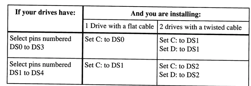
Table B - MFM and RLL Drive Jumpering
If your drives have: And you are installing:
1 Drive with a flat cable 2 drives with a twisted cable Select pins numbered Set C: to DSO Set C: to DS1
DSO to DS3 Set D: to DS1
Select pins numbered Set C: to DS1 Set C: to DS2
DS1 to DS4 Set D: to DS2
Always connect drive C: to the last connector (after the twist). Connect D: to the middle connector (before the twist).
IDE Driye .Iumpering
Most IDE drives have one or more of the following jumpers: HOST SLY/ACT, C/D, DSP, and ACT.
Drive Setup and Jumpering
DSO or DSI Confusion
Drive select jumpers are often a source of confusion and frustration. It seems that some manufac-turers label their four drive-select jumpers DSO, DS 1, DS2, and DS3. Others label them DS 1, DS2, DS3, and DS4.
If you are installing a single MFM or RLL drive in your system, choose DSO if your jumpers start with DSO or choose DS 1 if your jumpers start with DS 1. These are actually the same jumpers, just numbered differently by the drive manufacturer. What you need in a single drive MFM/RLL installation is the first available drive-select jumper.
If you are installing a second MFM or RLL drive in your system with a twisted cable, choose DS 1 if your jumpers start with DSO or choose DS2 if your jumpers start with DS 1. What you really want in this case is the second drive select jumper.
SCSI drive jumpering is an altogether different story. SCSI drives usually use three jumpers for addressing. The eight possible on/off configurations of these jumpers represent eight SCSI addresses. Normally these jumpers follow a straight-forward binary sequence with the lowest numbered jumper being the LSB. Check your drive manual to be sure before jumpering your SCSI drive.
Table B - MFM and RLL Drive Jumpering
If your drives have: And you are installing:
1 Drive with a flat cable 2 drives with a twisted cable Select pins numbered Set C: to DSO Set C: to DS1
DSO to DS3 Set D: to DS1
Select pins numbered Set C: to DS1 Set C: to DS2
DS1 to DS4 Set D: to DS2
Always connect drive C: to the last connector (after the twist). Connect D: to the middle connector (before the twist).
IDE Driye .Iumpering
HSP, whenjumpered, grounds the HOST/SLAVE/ACTIVE signal on the IDE inter-face. This signals to the system that a slave drive is present in a two drive system.
cm
is also sometimes labeled DS and is the drive select jumper. This jumper is set on the master (i.e. C:) drive and removed on the slave (i.e. D:) drive.DSP should only bejumpered on the first drive (ie. C:) if two IDE drives are installed in the same system. This jumper tells the master (i.e. C:) drive that there is another drive present on the IDE cable.
The ACT jumper connects the -ACTIVE signal to the -HOST SLY/ACT signal on the interface. This signal is often used to drive an external LED which indicates drive activity.
HSP, whenjumpered, grounds the HOST/SLAVE/ACTIVE signal on the IDE inter-face. This signals to the system that a slave drive is present in a two drive system.
cm
is also sometimes labeled DS and is the drive select jumper. This jumper is set on the master (i.e. C:) drive and removed on the slave (i.e. D:) drive.DSP should only bejumpered on the first drive (ie. C:) if two IDE drives are installed in the same system. This jumper tells the master (i.e. C:) drive that there is another drive present on the IDE cable.
Drive
Cabling
Twisted Cables
Why do many drive installations use twisted cables? Simply because IBM used them in the first PC's. In an effort to simplify installation, IBM decided to jumper all of their hard and floppy drives on the second drive select. This eliminated the need for technicians to jumper the drives. The first floppy drive (A:) was connected to the end of the cable (after the twist). The second floppy drive (B:) was connected before the twist. The twist in the cable simply flipped the first and second drive select lines so that all drives could be jumpered identically.
The floppy and hard drive cables in a standard AT look suspiciously similar. Be careful not to interchange them. A significant number of installation problems are a result of interchanged hard and floppy cables. Each cable has a different twist, and they are often not marked. If you are using twisted cables, make sure the floppy drive cable has seven conductors twisted. A twisted cable used with MFM or RLL hard drives must have only five conductors in the twist.
Sinele Drives (MFM. RLL or ESDI)
Cabling a single drive MFM, RLL, or ESDI system is easy. Use standard 20-pin flat data cable and a 34-pin control cable with no twist. A word of caution: watch out for pin one. Pin one is identified by a red stripe on one side ofthe cable. This side ofthe cable must be connected closest to pin one of both the drive and controller. Check the controller card for a small number 1 or a square dot on the silk screen near one edge of the connector. Pin 1 on the drive is nearest a notch in the edge connector. Reversing the data cable. can cause damage to the drive, controller, or both. The differential line drivers on the drive and controller are easily damaged by reversed cables. If you are not sure which is pin 1, check the manual, don't try to guess!
Multi Drive MFM and RLL Cabling
Three cables are required when installing two MFM or RLL drives using one controller. Two flat 20-pin data cables and one twisted 34-pin cable will be necessary. The 34-pin control cable should have only the drive select and ground pins twisted (5 conductors twisted). Set both drives to the second drive select position (This position is marked DSI or DS2 as described earlier in this section). Terminate the control cable on the last drive only.
Drive
Cabling
Twisted Cables
Why do many drive installations use twisted cables? Simply because IBM used them in the first PC's. In an effort to simplify installation, IBM decided to jumper all of their hard and floppy drives on the second drive select. This eliminated the need for technicians to jumper the drives. The first floppy drive (A:) was connected to the end of the cable (after the twist). The second floppy drive (B:) was connected before the twist. The twist in the cable simply flipped the first and second drive select lines so that all drives could be jumpered identically.
The floppy and hard drive cables in a standard AT look suspiciously similar. Be careful not to interchange them. A significant number of installation problems are a result of interchanged hard and floppy cables. Each cable has a different twist, and they are often not marked. If you are using twisted cables, make sure the floppy drive cable has seven conductors twisted. A twisted cable used with MFM or RLL hard drives must have only five conductors in the twist.
Sinele Drives (MFM. RLL or ESDI)
Cabling a single drive MFM, RLL, or ESDI system is easy. Use standard 20-pin flat data cable and a 34-pin control cable with no twist. A word of caution: watch out for pin one. Pin one is identified by a red stripe on one side ofthe cable. This side ofthe cable must be connected closest to pin one of both the drive and controller. Check the controller card for a small number 1 or a square dot on the silk screen near one edge of the connector. Pin 1 on the drive is nearest a notch in the edge connector. Reversing the data cable. can cause damage to the drive, controller, or both. The differential line drivers on the drive and controller are easily damaged by reversed cables. If you are not sure which is pin 1, check the manual, don't try to guess!
Multi Drive MFM and RLL Cabling
Multi Drive ESDI Cabline
Three cables are required when installing two ESDI drives using one controller. Two flat 20-pin data cables and one flat 34-pin cable with two drive connectors are necessary. Set the first ESDI drive jumpers to drive select
o.
Set the second drive to drive select 1. Terminate the control cable on the last drive only.Although most ESDI controllers support only two drives, the ESDI interface provides the ability to daisy-chain up to 8 drives. If you are installing more than two ESDI drives, use a flat 34-pin cable and set the selectjumpers sequentially. A separate 20-pin data cable is required for each drive.
IDE Drive CabHne
IDE (Imbedded Drive Electronics) interface disk drives use a 40-pin interface cable. This cable connects the drive logic (with imbedded controller) to a bus adapter card. This adapter is usually called a "paddle board". The paddle board buffers (amplifies) the signals from the drive and provides enough power to drive the PC bus.
Cabling an IDE drive is simple. Connect a 40-pin flat cable from the drive to the controller, being careful to observe pin 1 orientation. Ifthe drive supports it, a second IDE drive can usually be connected to the same cable. To do so,jumper the boot drive in "master" mode, and jumper the second drive as a "slave". Since the IDE interface transfers data and control signals at full bus speed, IDE cable lengths are critical. As a rule of thumb, try to avoid using a cable longer than 18" in any IDE drive installation.
SCSI Drive CabUne
Internal SCSI drives are connected to the controller with a 50-pin ribbon cable. Be extremely careful to observe the pin 1 location when connecting cables to SCSI drives. Reversing SCSI cables on drives often causes a loss oftermination power which can result in marginal data transfer or no transfer at all. Some external SCSI drives are connected to the controller with a 25-pin D-type connector, others use a 50-pin Amphenol connector. The SCSI bus must have a total of2 terminators - no more and no less. Ifyou are using the controller with one internal hard disk, for example, termination will be installed on the internal hard drive and on the controller card. If you are installing one internal and one external drive, the terminators must be removed from the controller card and installed on the internal and external drives. Check the manual included with your SCSI drives and controllers for terminator installation and removal.
Multi Drive ESDI Cabline
Three cables are required when installing two ESDI drives using one controller. Two flat 20-pin data cables and one flat 34-pin cable with two drive connectors are necessary. Set the first ESDI drive jumpers to drive select
o.
Set the second drive to drive select 1. Terminate the control cable on the last drive only.Although most ESDI controllers support only two drives, the ESDI interface provides the ability to daisy-chain up to 8 drives. If you are installing more than two ESDI drives, use a flat 34-pin cable and set the selectjumpers sequentially. A separate 20-pin data cable is required for each drive.
IDE Drive CabHne
IDE (Imbedded Drive Electronics) interface disk drives use a 40-pin interface cable. This cable connects the drive logic (with imbedded controller) to a bus adapter card. This adapter is usually called a "paddle board". The paddle board buffers (amplifies) the signals from the drive and provides enough power to drive the PC bus.
Cabling an IDE drive is simple. Connect a 40-pin flat cable from the drive to the controller, being careful to observe pin 1 orientation. Ifthe drive supports it, a second IDE drive can usually be connected to the same cable. To do so,jumper the boot drive in "master" mode, and jumper the second drive as a "slave". Since the IDE interface transfers data and control signals at full bus speed, IDE cable lengths are critical. As a rule of thumb, try to avoid using a cable longer than 18" in any IDE drive installation.
SCSI Drive CabUne