Ion Species
/
Energy Dependence of Irradiation-Induced Lattice Structure
Transformation and Surface Hardness of Ni
3Nb and Ni
3Ta Intermetallic
Compounds
H. Kojima
1,*, Y. Kaneno
1, M. Ochi
1, S. Semboshi
2, F. Hori
1, Y. Saitoh
3, N. Ishikawa
4, Y. Okamoto
5and A. Iwase
11Department of Materials Science, Osaka Prefecture University, Sakai 599–8531, Japan
2Trans-Regional Corporation Center for Industrial Materials Research, Institute for Materials Research, Tohoku University, Sakai 599–8531, Japan
3National Institutes for Quantum and Radiological Science and Technology, Takasaki 370–1292, Japan 4Nuclear Science and Engineering Center, Japan Atomic Energy Agency, Tokai 319–1195, Japan 5Materials Science Research Center, Japan Atomic Energy Agency, Tokai 319–1195, Japan
Bulk samples of Ni3Nb and Ni3Ta intermetallic compounds were irradiated with 16 MeV Au, 4.5 MeV Ni, 4.5 MeV Al, 200 MeV Xe and
1.0 MeV He ions, and the change in near-surface lattice structure was investigated by means of the grazing incidence x-ray diffraction (GIXD) and the extended x-ray absorption fine structure (EXAFS). The Ni3Nb and Ni3Ta lattice structures transform from the ordered structures
(ort-horhombic and monoclinic structures for Ni3Nb and Ni3Ta, respectively) to the amorphous state by the Au, Ni, Al and Xe ion irradiations.
Irre-spective of such heavy ion species or energies, the lattice structure transformation to the amorphous state almost correlate with the density of energy deposited through elastic collisions. In the case of the samples irradiated with 1.0 MeV He ions, however, no amorphization was ob-served even when the density of elastically deposited energy is the same as that for Au irradiated sample which showed the amorphous phase. The change in Vickers hardness induced by the amorphization was also measured and was discussed in terms of ion fluence and the density of deposited energy. [doi:10.2320/matertrans.MBW201612]
(Received January 24, 2017; Accepted February 17, 2017; Published March 27, 2017)
Keywords: Ni3Nb, Ni3Ta, ion irradiation, dependence on deposited energy density, lattice structure transformation, Vickers hardness, amor-phization
1. Introduction
Conventionally, the processes of quenching, forging or rolling have been used so far as a method for modifying met-al materimet-als. These processes utilize the thermmet-al energy and/ or strain energy which are deposited into materials. While, energetic ion beam irradiation is also a potential method to deposit the energy into materials and to modify various mate-rial properties. Some readers may think of the ion implanta-tion as a method of materials modificaimplanta-tion by using ion beam irradiation. The ion implantation process has often been used so far to inject various atoms into matrix materials1). While on the other hand, the energy deposited by ions has almost ex-clusively been used to simulate degradation or damage on the structure and several properties of materials related to nuclear power plants and space crafts (so called Radiation Dam-age )2). However, energetic ion irradiation locally gives high density energy deposition into a target, and it can induce non-thermal equilibrium phases. Therefore, the ion irradia-tion can add various new properties to materials, which can-not be realized by conventional materials processing meth-ods. Also, the effect of energetic ion irradiation on materials can be controlled by changing ion species, energies and/or ion fluence.
In the present study, we have used bulk Ni-based interme-tallic compounds as target materials. Intermeinterme-tallic com-pounds show various characteristic properties such as high temperature strength3), oxidation resistance4), hydrogen stor-age5), superconductivity6) or shape memory7), depending on
their chemical compositions. The varieties of these properties derive from the difference in their ordered lattice structures.
Mainly in 1980s and 1990s, a lot of researchers reported lattice disordering and amorphization phenomena induced by charged particle irradiations for various intermetallic com-pounds such as NiTi8–11), NiAl9,12), NiAl
313), Ni2Al314), FeAl12), Zr
3Fe15,16), ZrFe216), ZrCr216), Zr3Al17,18), NiZr219), NiZr19), Ni
3Zr19). AuIn220), In2Pd20) and CuTi21). Especially,
in-situ observations under MeV electron irradiation by using high voltage transmission microscopes (HVEM) has often been used for the investigation of the dependence of irradia-tion-induced amorphization and lattice disordering on irradi-ation temperature, dose rate and total dose of irradiating elec-trons8,15,19). Even reecently, by using HVEM, new results for the electron beam induced amorphization for CoTi, Co3Ti, Cr2Ti, Cr2Al, Ti2Pd, and TiNi1−xFex have been reported22–25). To clarify the amorphization kinetics, some theoretical ap-proaches and computer simulations have also been per-formed11,26–29). The tendency to be disordered or amorphized by the irradiation, however, strongly depend on the kinds of target intermetallic compounds. Therefore, to understand ful-ly the mechanism of irradiation-induced amorphization and lattice disordering, we have to perform irradiation experi-ments also for intermetallic compounds which have never been investigated yet. Moreover, in most of previous studies, not bulk but thin film samples have been used to perform the lattice structure observation by means of transmission elec-tron microscopes (TEM). As target surfaces act as selec-trong sinks against irradiation-produced lattice defects, effects of the irradiation on lattice structures of thin films are expected to be different from those of bulk samples. In addition, if we
* Corresponding author, E-mail: [email protected]
chose thin film samples as ion irradiation targets, it would be difficult to investigate the irradiation effects on macroscopic properties of them, such as mechanical, magnetic and electri-cal properties. Recently, our research group has used energet-ic ion irradiations to modify the lattenerget-ice structure and the me-chanical property of bulk intermetallic compounds. In partic-ular, we have chosen Ni-based intermetallic compounds as ion irradiation targets because they are applied for structural materials30,31). They are promising as a next generation type of high temperature materials and it is needed to investigate not only structure transformation, but also mechanical prop-erty. In our previous results, we showed the lattice structure transformation, which was induced by energetic ion irradia-tion, and the change in Vickers hardness for Ni3Al32), Ni3V33,34), Ni3Nb and Ni3Ta35) intermetallic compounds. At room temperature, Ni3V intermetallic compound shows the tetragonal ordered structure (D022 structure), and Ni3Al inter-metallic compound shows the cubic ordered structure (L12 structure). However, both ordered structures change into the disordered fcc structure (A1 structure) by the energetic ion irradiation32–34). While for Ni
3Nb and Ni3Ta intermetallic compounds, the lattice structures transformed from the or-dered orthorhombic or monoclinic structure to the amorphous state by the ion irradiation35). These results were obtained un-der the same irradiation condition that all intermetallic com-pound samples were irradiated with 16 MeV Au ions at room temperature. Also, we have performed Al and I ion irradiation for Ni3Al intermetallic compound and confirmed the transi-tion to the disordered fcc structure32).
To use the energetic ion beam irradiation as a tool for ma-terial modifications, we need to find irradiation parameters which dominate the irradiation effect. In the present study, we have paid attention to ion species and energy dependence of the structural change from the ordered structure to the amor-phous state in Ni3Nb and Ni3Ta interatomic compounds from the point of view of energy deposition through the electronic excitation and the elastic collisions.
In addition to the use of bulk samples instead of thin films, another advantage of our study is to utilize the extended X-ray absorption fine structure (EXAFS) spectroscopy at a synchrotron facility as a means to estimate the change in lat-tice structure. As EXAFS is so called non-destructive meth-od, we do not need to make thin films but can use bulk sam-ples also for the EXAFS measurements, which are used for the irradiation and hardness measurements. Moreover, through the EXAFS measurement, we can observe local atomic arrangements around selected atomic elements, i.e, Nb or Ta in the present study. Such information will be quite useful for the investigation of irradiation effects on the lattice structure of intermetallic compounds. In this report, we will also show the ion species and energy dependence on hardness for Ni3Nb and Ni3Ta intermetallic compounds.
We have chosen 16 MeV Au ions, 4.5 MeV Ni ions, 4.5 MeV Al ions, as irradiating ions to Ni3Nb and Ni3Ta tar-gets. In addition to these ions irradiation, we have performed 1.0 MeV He ions irradiation to the two kinds of targets. For Ni3Nb, 200 MeV Xe ion irradiation was also performed. Al-though some results for the Au ion irradiation have already been reported35), we will discuss here the ion species/energy dependence on the irradiation effect including the previous
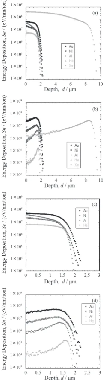
results of Au ion irradiation. As can be seen in Fig. 1, the shapes of the depth profiles of energy deposition by 16 MeV Au, 4.5 MeV Ni, 4.5 MeV Al and 1.0 MeV He ions for Ni3Nb and Ni3Ta are approximately the same. This point is very im-portant when effects of ion irradiation are compared among several ion irradiations with different species and/or ener-gies. Moreover, the Ni ion irradiation, what is called, the self-ion irradiation will reveal whether the lattice structure transformation is affected by the accumulation of irradiating ions or not. The value of electronic stopping power, Se, for 200 MeV Xe ion irradiation is much larger than that for 1.0 MeV He, 4.5 MeV Al, 4.5 MeV Ni or 16 MeV Au ions. Through such high-Se ion irradiation experiment, therefore, we can discuss the contribution of the high density electronic excitation to the irradiation-induced lattice structure transfor-mation of Ni3Nb.
2. Experimental Procedure
Ingots of Ni3Nb and Ni3Ta were manufactured by arc melt-ing and subsequently homogenized at 1273 K for 96 and 144 hours, respectively. The two kinds of ingots were cut into sheet-type samples and mechanically polished. Ni3Nb sam-ples were irradiated at room temperature with 16 MeV Au5+, 4.5 MeV Ni2+, 4.5 MeV Al2+ and 1.0 MeV He+ by using 3-MV tandem accelerator and a single-ended accelerator at Takasaki Advanced Radiation Research Institute, National Institutes for Quantum and Radiological Science and Tech-nology. Some Ni3Nb samples were also irradiated with 200 MeV Xe+14 ions by using 20-MV tandem accelerator at Nuclear Science Research Institute, Japan Atomic Energy Agency. Ni3Ta samples were irradiated with 16 MeV Au5+, 4.5 MeV Ni2+, 4.5 MeV Al2+ and 1.0 MeV He+ ions at room temperature. The irradiation parameters are listed in Table 1. Figures 1(a) and 1(b) show the depth profiles of the energy deposited through the electronic excitation and the elastic collisions by one ion per unit path length for 16 MeV Au5+, 4.5 MeV Ni2+, 4.5 MeV Al2+, 200 MeV Xe+14 and 1.0 MeV He+ ion irradiations in Ni
3Nb intermetallic compound. Fig-ures 1(c) and 1(d) show the depth profiles for 16 MeV Au5+, 4.5 MeV Ni2+, 4.5 MeV Al2+ and 1.0 MeV He+ ions irradia-tion in Ni3Ta intermetallic compound. These profiles were calculated by using the SRIM code36). For the calculations, we used the value of 9.09 g/cm3 and 12.04 g/cm3 as the den-sity of Ni3Nb and Ni3Ta samples, respectively. As can be seen in the figure, the effect of the ion irradiation is restricted only at the region from the sample surface to the depth of about 2 μm except for Xe ion irradiation, the depth affected by which is about 10 μm. Therefore, we have chosen the grazing incidence X-ray diffraction (GIXD) to observe the surface lattice structures (from the surface to the depth of about 200 nm).
were Fourier transformed using k3 weighting with the k range from 20–30 to 100–150 nm−1.
We performed the micro Vickers hardness measurements at room temperature for unirradiated and irradiated Ni3Nb and Ni3Ta samples. To detect the hardness near the sample sur-face, the applied load was 10 gf (98.07 mN). The time inter-val of indentation was kept at 10 seconds. Indent depth is about 1 μm which is enough to cover the irradiated region of sample surface.
3. Results and Discussion
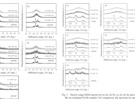
First of all, we discuss the change in surface lattice struc-tures by the ion irradiations. Figure 2 shows the wide-scanned GIXD spectra for Ni3Nb samples irradiated with Au, Ni, Al, Xe and He ions. For comparison, the result for the unirradiat-ed sample is also shown. For the spectrum of the unirradiatunirradiat-ed Ni3Nb, several diffraction peaks are clearly observed. These peaks correspond the orthorhombic ordered structure which is the thermal equilibrium phase of Ni3Nb at room tempera-ture38). To see the change in spectra in more detail, Fig. 3 shows the narrow-scanned spectra around 43 for the Ni3Nb samples irradiated with Au, Ni, Al, Xe and He ions. The in-tensity of each peak decreases with increasing the ion fluence. To emphasize the change in shape of the GIXD peak by each irradiation, all the peaks are normalized as the intensity of the highest peak for each spectrum becomes unity and are plotted in the figure. For the Ni3Nb samples irradiated with 4.5 MeV Ni ions (Fig. 3(b)), the peaks corresponding to the orthor-hombic structure completely disappear for fluences of 2.5 × 10¹⁸/m2 and 2.5 × 10¹⁹/m2, and a broad peak appears around 43 . The broad XRD spectra for the Ni ion irradiation are sim-ilar to the spectra for Au ion irradiation35) (Fig. 3(a)). A Ni
3Nb intermetallic compound matrix consists of Ni and Nb atoms. Even when Ni ions are implanted into Ni3Nb matrix with the fluence of 2.5 × 10¹⁹/m2, the total number of Ni atoms near Fig. 1 Depth profiles of energies deposited through (a) electronic excitation
and through (b) elastic collision for one ion per unit path length for 16 MeV Au5+, 4.5 MeV Ni2+, 4.5 MeV Al2+, 200 MeV Xe+14 and 1.0 MeV
He+ ion irradiation in Ni
3Nb alloys, and depth profiles of energies
depos-ited through (c) electronic excitation and through (d) elastic collision and for one ion per unit path length for 16 MeV Au5+, 4.5 MeV Ni2+, 4.5 MeV
Al2+ and 1.0 MeV He+ ion irradiation in Ni
3Ta. (a) Ni3Nb, (b) Ni3Nb, (c)
[image:3.595.81.253.72.703.2]Ni3Ta, (d) Ni3Ta.
Table 1 Irradiation parameters.
Target Ion species Au
5+ Ni2+ Al2+ Xe14+ He+
Energy 16 MeV 4.5 MeV 4.5 MeV 200 MeV 1.0 MeV
Ni3Nb
Projected
Range[µm] 1.54 1.48 1.51 8.57 1.59
Se
[keV/nm] 6.32×100 2.85×100 4.92×100 3.95×101 7.21×10⁻¹ Sn
[keV/nm] 2.87×1004.72×10−16.52×10−21.67×10−11.23×10⁻³
Ion Fluence [m−2]
1.0×10¹⁷ 5.0×10¹⁷ 5.0×10¹⁸ 1.0×10¹⁸ 4.0×10²⁰
5.0×10¹⁷ 2.5×10¹⁸ 1.0×10¹⁹ 5.0×10¹⁸ 1.2×10²¹
5.0×10¹⁸ 2.5×10¹⁹ 1.0×10²⁰ 1.6×10¹⁹ 1.7×10²¹
Ni3Ta
Projected
Range[µm] 1.42 1.35 1.44 1.59
Se
[keV/nm] 6.16×100 2.77×100 4.81×100 7.08×10⁻¹ Sn
[keV/nm] 3.31×1005.31×10−17.36×10⁻² 1.38×10⁻³
Ion Fluence [m−2]
1.0×10¹⁷ 5.0×10¹⁷ 5.0×10¹⁸ 4.0×10²⁰
5.0×10¹⁷ 2.5×10¹⁸ 1.0×10¹⁹ 1.2×10²¹
[image:3.595.305.549.81.330.2]the surface of Ni3Nb does scarcely change, and accumulated Ni ions does not have any effect on the GIXD spectrum. Therefore, the spectrum change by the Ni ion irradiation is caused by the energy transferred from the energetic Ni ions to the sample and not by the accumulation of Ni ions in the sam-ple. For the change in the spectra by the Al ion irradiation (Fig. 3(c)), the same tendency has been observed as that for the Ni ion irradiation. The peaks corresponding to the orthor-hombic structure completely disappear and a broad peak ap-pears around 43 by the Al ion irradiation with fluence of 1.0 × 10²⁰/m2. However, for the Au ion irradiated samples, a broad peak is observed with the fluence of 5.0 × 10¹⁷/m2 and 5.0 × 10¹⁸/m2. Also, a similar peak is confirmed in Ni ion ir-radiated samples with fluence of 2.5 × 10¹⁸/m2 and 2.5 × 10¹⁹/m2. This result shows that for the irradiation with small-er mass ions, a largsmall-er fluence is needed to change the lattice structure of the Ni3Nb samples. Such a trend becomes more remarkable in the case of 1.0 MeV He ion irradiation (Fig. 3(e)). Even for the fluence of 1.7 × 10²¹/m2, the lattice structure of the Ni3Nb sample is never changed, but the peaks for the orthorhombic structure are still clearly observed. The spectrum changes have also been observed for the 200 MeV Xe ion irradiation (Fig. 3(d)). In the spectrum with the flu-ence of 1.6 × 10¹⁹/m2, all the peaks for the orthorhombic lat-tice structure disappear, and a broad peak appears around 43 . It is well known that a broad peak in XRD spectrum
indi-cates a state which loses the long-range ordering of atomic arrangements39). This is like liquid, what is called an amor-phous state. Therefore, irrespective of heavy ion species, the lattice structure of Ni3Nb tends to transform by the irradiation from the orthorhombic ordered structure to the amorphous state even at room temperature. The critical ion fluence which causes the amorphization, however, depends on the ion spe-cies and/or ion energy. In the case of 1.0 MeV He ion irradi-ation, within the ion-fluece range of the present experiment, the amorphization was not observed. The formation of the amorphous phase for Ni-Nb alloy by liquid quenching has been reported40). The change in XRD spectra by the liquid quenching is similar to that observed in the present irradiation experiment.
We have found a similar irradiation effect for the Ni3Ta intermetallic compound. Figure 4 shows the results of nar-row-scanned GIXD spectra for the unirradiated Ni3Ta sample and those irradiated with 16 MeV Au, 4.5 MeV Ni, 4.5 MeV Al and 1.0 MeV He ions. The spectrum for the unirradiated sample corresponds to the monoclinic ordered lattice struc-ture, which is a thermal equilibrium structure of Ni3Ta at room temperature41). After the irradiation, the peaks corre-sponding to the monoclinic structure tend to disappear with increasing in ion fluence. For Au, Ni or Al ion irradiation they nearly completely disappear and the broad peak appears around 43 degree for the irradiation with high fluences. Therefore, this result implies that Ni3Ta tends to transform from the monoclinic ordered structure to the amorphous state by each ion irradiation at room temperature. However, for He ion irradiation (Fig. 4(d)), ordered peaks remain to the high Fig. 2 Wide-range GIXD spectra for (a) Au, (b) Ni, (c) Al, (d) Xe and (e)
He ion irradiated Ni3Nb samples. For comparison, the spectrum for
unir-radiated specimen is shown in each figure.
Fig. 3 Narrow-range GIXD spectra for (a) Au, (b) Ni, (c) Al, (d) Xe and (e) He ion irradiated Ni3Nb samples. For comparison, the spectrum for
[image:4.595.48.293.55.421.2] [image:4.595.103.543.60.381.2]fluence of 1.7 × 10²¹/m2.
Figure 5 shows the k3-weighted EXAFS spectra around Ta L3 absorption edge for unirradiated Ni3Ta and Ni3Ta samples irradiated with the Au and Ni ions, and their EXAFS – FT spectra. When paying attention to the first peak which corre-sponds to nearest neighbor atoms for the Ta atom, even after
the irradiation, it is still more outstanding than any other peaks which are strongly suppressed or nearly disappear by the irradiation. The same effect of the ion irradiation on the EXAFS spectrum has already been observed for the Au ion-irradiated Ni3Nb35), which is shown in the Fig. 6. The present EXAFS results clearly confirm that the amorphiza-tion is induced by the ion irradiaamorphiza-tion in the both materials, i.e., the long range ordering tends to disappear and only the short range ordering still survives the irradiation.
In our previous study35), we performed only the Au ion ir-radiation for Ni3Nb and Ni3Ta intermetallic compounds. In the present study, we have investigated the lattice structure transformation by using five kinds of ion species with differ-ent energies. Therefore, we can discuss irradiation parameters for describing the irradiation-induced amorphization. First of all, the GIXD results for Ni3Nb are summarized in terms of ion fluence in Fig. 7. Open circles show the amorphous state and X-marks show the ordered crystal structure. A trian-gle-mark shows the case where it is difficult to decide wheth-er the specimen is completely amorphized or not. The figure indicates that there does not exist any clear correlation be-tween the transformation to the amorphous state and the ion Fig. 4 Narrow-range GIXD spectra for (a) Au, (b) Ni, (c) Al and (d) He ion
irradiated Ni3Ta samples. For comparison, the spectrum for unirradiated
specimen is shown in each figure. Indices on spectrum for unirradiated sample correspond to the monoclinic structure.
Fig. 5 (a) k3-weighted EXAFS spectra around Ta L3 absorption edge for
unirradiated Ni3Ta specimen and those irradiated with Au or Ni ions, and
[image:5.595.84.258.65.641.2] [image:5.595.327.524.66.460.2]fluence.
Next, we consider the processes of energy deposition by the energetic ions in materials. When an energetic ion pene-trates a target, it loses its energy via two nearly independent processes: the energy loss through the elastic collisions, which dominate the energy loss of ions in the low energy range, and the energy loss through the electronic excitation and ionization, which overwhelm the energy loss through the elastic collisions in the high energy range. To discuss the ion-irradiation induced amorphization in Ni3Nb in terms of the two interaction processes, the density of energy deposited through the electronic excitation, Eelec, and that through the elastic collisions, Eelas, in the region observed by the GIXD measurement have been calculated by using the following equation;
Eelec=<Se>φ (1)
Eelas=<Sn>φ, (2)
where, <Se> and <Sn> are the average values of electronic
stopping power, Se, and the nuclear stopping power, Sn, which
were calculated from the sample surface to the depth of about 200 nm, which is a region observed by the GIXD method, and ϕ is the ion-fluence Since the changes of Se and Sn in relation to the depth are quite small near the surface, the val-ues of Se and Sn for each ion with the incident energy can
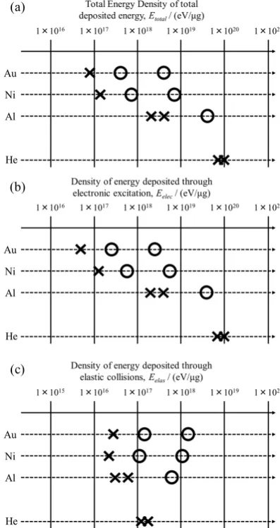
used instead of the averaged values of <Se> or <Sn>. The values of Se and Sn, for each ion species and the ion fluence are listed in Table 1. Figure 8(a) shows the transformation of the lattice structure for Ni3Nb samples in terms of the total deposited energy density, (Eelec + Eelas). Figure 8(b) shows the lattice structure transformation in terms of Eelec. According to these figures, the transformation to the amorphous state does not well correlate with the density of the total deposited ener-gy or the density of enerener-gy deposited by the electronic exci-tation process, Eelec. Finally, we have paid attention to the density of energy deposited through the elastic collisions, Eelas. As can be seen in Fig. 8(c), the transformation to the amorphous state correlate with the energy deposited through elastic collisions, Eelas, much better than total deposited ener-gy density or that deposited by the electronic excitation, Eelec. Strictly speaking, however, in the case of Al and Xe ion irra-diations, it seems that a larger value of Eelas is necessary for the amorphization of Ni3Nb than for the case of Au and Ni ion irradiation. In comparison to the result for 1.0 MeV He ion irradiation, this tendency is more remarkable. In Fig. 9 the GIXD spectrum for Au ion irradiation with the fluence of 5.0 × 10¹⁷/m2 is compared with that for He ion irradiation with the fluence of 1.2 × 10²¹/m2. Although the value of E
elas Fig. 6 FT EXAFS spectra around Nb K absorption edge for the
unirradiat-ed Ni3Nb specimen and that irradiated with Au ions13).
Fig. 7 Lattice structure transformation for Ni3Nb in terms of ion influence.
Fig. 8 Lattice structure transformation for Ni3Nb in terms of (a) density of
[image:6.595.69.272.56.271.2] [image:6.595.326.524.66.443.2] [image:6.595.69.268.322.436.2]is about the same for the two kinds of irradiation, (Eelas is about 1.6 × 10¹⁷ eV/μg), the Au ion irradiated sample shows a broad peak corresponding to the amorphous phase, but the He ion irradiated sample is not amorphized yet and some peaks which correspond to the orthorhombic structure can still be observed.
The same data analysis has been performed for the Ni3Ta samples. Figure 10 and Figs. 11(a), (b) and (c) show the lat-tice structure transformation from the monoclinic phase to the amorphous phase in terms of ion-fluence, density of total de-posited energy, density of energy dede-posited by the electronic excitation and density of energy deposited by elastic colli-sions, respectively. The figures indicate that the amorphiza-tion of Ni3Ta samples correlates with the density of energy deposited by elastic collisions, Eelas, much better than the density of total deposited energy or that by electronic exci-tation. The amorphization of Ni3Ta is, however, not described only by Eelas, which is shown clearly in Fig. 12. Even by the irradiation with the same value of Eelas, the amorphization oc-curs by the Au ion irradiation, but the monoclinic structure still exists after the He ion irradiation.
Here, we discuss the meaning of Eelas as a parameter for describing irradiation effects. The value of Eelas is the density of energy which is directly transferred from an incident ion to the target atoms. The transferred energy causes the displace-ment of target atoms from their regular lattice sites if the transferred energy is larger than some value (the displace-ment threshold energy, Ed). The atoms displaced from the lat-tice sites are called Primary Knock-on Atom (PKA) . The total number of displacements per one atom is called dpa (displacements per atom) and has often been used as a unit of
irradiation dose especially in the research field of radiation damage for nuclear materials. The value of dpa is nearly pro-portional to the value of Eelas for energetic (>1 MeV) ions. Therefore, if an irradiation effect is well correlated with the value of Eelas, the effect is attributed to the total number of atomic displacements or the accumulation of individual Fig. 9 Comparison of GIXD spectra for Au ion irradiated and He ion
irra-diated Ni3Nb specimens. Density of energy deposited through elastic
[image:7.595.64.267.67.194.2]col-lisions is the same (1.6 × 10¹⁷ eV/μg) for the both irradiations.
[image:7.595.325.524.71.446.2]Fig. 10 Lattice structure transformation for Ni3Ta in terms of ion influence.
Fig. 11 Lattice structure transformation for Ni3Ta in terms of (a) density of
total deposited energy (elastic collisions and electronic excitation), (b) density of energy deposited through electronic excitation and (c) that through elastic collision.
Fig. 12 Comparison of GIXD spectra for Au ion irradiated and He ion irra-diated Ni3Ta specimens. Density of energy deposited through elastic
[image:7.595.69.268.262.378.2] [image:7.595.322.526.521.652.2]atomic displacement. In many cases, however, irradiation ef-fects are not well described only by dpa. Another important parameter for the description of irradiation effects is the spec-trum or the energy of primary knock-on atom (PKA). If the PKA energy is large, its energy is transferred in the narrow region of the target, causing the collective displacements or displacement cascade. For the ions used in the present irradi-ation, except for 200 MeV Xe ion irradiirradi-ation, the average PKA energy is larger for the irradiation with larger mass ions. The present result clearly shows that the irradiation with the largest mass ions (Au ions) amorphizes the Ni3Nb and Ni3Ta samples much more effectively than the irradiation with the smallest mass ions (He ions). Therefore, to understand the mechanism of the ion irradiation-induced amorphization of Ni3Nb and Ni3Ta, not only the accumulation of individual atomic displacement but also the collective displacements or displacement cascade by high energy PKAs have to be con-sidered. The particle species dependence of the amorphiza-tion of Ni3Nb and Ni3Ta is similar to that for the irradia-tion-induced amorphization of AuIn220), Zr3Fe16) and NiAl313). The amorphization of AuIn2 by He ions requires much higher dpa-values than those necessary for the amorphization by heavy ions20). The critical temperature for the amorphization of Zr3Fe by electron irradiation is about 220 K, which is much lower than 570–600 K for Ar ion irradiation16). At 100 K, the NiAl3 was completely transformed into an amor-phous state for Xe, Ne, and electrons. At 300 K only Xe irra-diation produced a complete transformation to the amorphous state. The critical temperature for the amorphization depends on irradiating ion species13). The difference in amorphization between by light ions or electrons and by heavy ions, which have commonly been observed in many kinds of intermetallic compounds, can be explained as follows; for heavy ion irradi-ation, the direct amorphization inside the displacement cas-cade occurs, and for light ion or electron irradiation, the amorphization is caused as a result of point defect accumula-tion.
It has been reported so far that some intermetallic com-pounds such as NiZr242), RCo2 and RCo3 (R = rare earth ele-ments)43), and NiTi44) show lattice structure transformation through the high density electronic excitation. On the other hand, in the case of Ni3Nb and Ni3Ta, the present study shows that the energy deposited through the electronic excitation does little affect the lattice structure transformation. The val-ue of electronic stopping power, Se, for 200 MeV Xe ion irra-diation is much larger than for other four ions. As can be seen in Fig. 8(c), however, the energy deposited by the elastic col-lisions dominates the irradiation-induced amorphization even for the 200 MeV Xe ion irradiation.
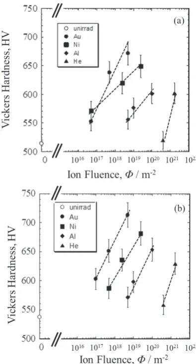
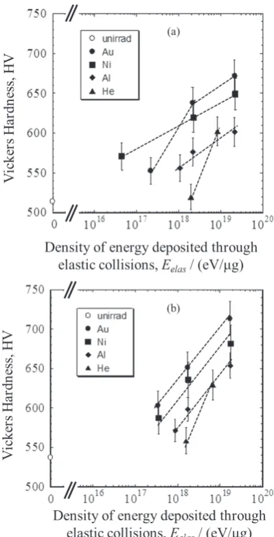
Figure 13(a) (b) show the Vickers hardness for Ni3Nb and Ni3Ta as a function of ion fluence. The result shows that the hardness increases with increasing the ion-fluence. At a given ion-fluence, the increase in hardness is larger for the irradia-tion with larger mass ions. This ion species dependence is similar to that for the GIXD result. Then, in Fig. 14, the Vick-ers hardness change is plotted as a function of the density of energy deposited through elastic collision. It is worth noting here that the density of elastically deposited energy is differ-ent from the value of Eelas we have used for the analysis of GIXD results. As the GIXD measures only the lattice
struc-ture near the sample surface, the value of Sn for the incident energy can be used. By contrast, the Vickers hardness tester measures the hardness for the whole of region affected by the irradiation. Therefore, for the plot in Fig. 14, we used the av-eraged density of elastically deposited energy, <Eelas>, which was calculated by the following equation,
<Eelas>= R
0
Sn(x)dx/R ×φ (3)
where, Sn(x) is the nuclear stopping power as a function of depth, x, R is the projected range of each ion, and ϕ is the ion fluence. As is similar to the case of GIXD result, for the de-scription of the irradiation-induced increase in hardness, the density of energy deposited through elastic s, < Eelas> is bet-ter than ion-fluence, and the < Eelas> dependence of hardness can correspond to the conventional knowledge that the hard-ness for the amorphous state is larger than that for the crystal-line structure. Figure 14, however, shows that the experimen-tal data for Al and He ion irradiations largely deviate from the curve for Au and Ni ion irradiations. This result implies that other factors should also be considered in addition to the elas-tically deposited energy. To clarify the ion species/energy dependence of hardness, the nano-indentation measurement, which detect the hardness only near the sample surface, where the values of Se and Sn little change, is now in prog-Fig. 13 Vickers hardness as a function of ion fluence for (a) Ni3Nb and (b)
[image:8.595.326.524.68.435.2]ress.
4. Summary
Bulk samples of Ni3Nb and Ni3Ta intermetallic compounds were irradiated at room temperature with 16 MeV Au, 4.5 MeV Ni, 4.5 MeV Al and 1.0 MeV He ions. Some Ni3Nb samples were also irradiated with 200 MeV Xe ions. The ef-fects of the ion irradiation on the lattice structure were inves-tigated by means of GIXD and EXAFS. The effect of the ion irradiation on the surface hardness was examined by using a Vickers hardness tester. The amophization was observed in Au, Ni, Al and Xe irradiated samples. This phenomenon is almost correlated with the density of energy deposited through the elastic collisions. In the case of the samples irra-diated with 1.0 MeV He ions, no amorphization was observed even when the density of elastically deposited energy is the same as that for Au irradiated sample which showed the amorphous state. The Vickers hardness increased with in-creasing ion fluence, but the hardness does little correlate with the ion fluence or the density of elastically deposited energy. The present result implies that to understand the ef-fect of energetic ion irradiation on the lattice structure and the
surface hardness of Ni3Nb and Ni3Ta, not only the energy deposited through elastic collisions (total number of atomic displacements) but also other irradiation factors such as the energy spectrum of primary knock on atoms have to be con-sidered.
Acknowledgments
The authors would like to thank the staff of Takasaki Ad-vanced Radiation Research Institute, National Institutes for Quantum and Radiological Science and Technology for oper-ating the 3-MV tandem and the single-ended accelerators. They also thank the staff of Nuclear Science Research Insti-tute, Japan Atomic Energy Agency for operating 20-MV tan-dem accelerator. The present study has been carried out under the collaboration program between Osaka Prefecture Univer-sity and National Institutes for Quantum and Radiological Science and Technology and that between Osaka Prefecture University and Japan Atomic Energy Agency.
REFERENCES
1) V.I. Lavrentiev and A.D. Pogrebnjak: Surf. Coat. Tech. 99 (1998) 24.
2) S. Was, Fundamentals of Radiation Materials Science , Metals and Alloy, Springer 2007.
3) N. Masahashi, T. Takasugi and O. Izumi: J. Mater. Sci. 22 (1987) 2599.
4) M.-R. Yang and S.K. Wu: Oxid. Met. 54 (2000) 473.
5) Y. Naik, G.A. Rama Rao and V. Venugopal: Intermetallics 9 (2001) 309.
6) M. Mudgel, V.P.S. Awana, G.L. Bhalla and H. Kishan: Solid State Commun. 147 (2008) 439.
7) Y.N. Koval, G.S. Firstov and A.V. Kotko: Scr. Metall. Mater. 27 (1992) 1611.
8) S. Watanabe, T. Koike, T. Suda, S. Ohnuki and H. Takahashi: Mater. Trans. 45 (2004) 21.
9) P. Moine and C. Jaouen: J. Alloy. Compd. 194 (1993) 373.
10) J. Cheng and A.J. Ardell: NIMB 44 (1990) 336.
11) D.F. Pedraza: Mater. Sci. Eng. 90 (1987) 69.
12) L. Thomé, C. Jaouen, J.P. Riviere and J. Delafond: NIMB 19–20 (1987) 554.
13) M. Nastasi, J.M. Williams, E.A. Kenik and J.W. Mayer: NIMB 19–20 (1987) 543.
14) M. Nastasi: J. Less Common Met. 168 (1991) 91.
15) A.T. Motta, L.M. Howe and P.R. Okamoto: Nucl. Mater. 270 (1999) 174.
16) L.M. Howe, D. Phillips, A.T. Motta and P.R. Okamoto: Surf. Coat. Tech. 66 (1994) 411.
17) W.J. Meng, P.R. Okamoto, L.J. Thompson, B.J. Kestel and L.E. Rehn:
Appl. Phys. Lett. 53 (1988) 1820.
18) G.J.C. Carpenter and E.M. Schulson: J. Nucl. Mater. 73 (1978) 180.
19) G.B. Xu, M. Meshii, P.R. Okamoto and L.E. Rehn: J. Alloy. Compd.
194 (1993) 401.
20) A. Plewnia, B. Heinz and P. Ziemann: NIMB 148 (1999) 901.
21) J. Koike, P.R. Okamoto and M. Meshii: J. Non-Cryst. Solids 106 (1988) 230.
22) S. Anada, A. Zensho, H. Yasuda and H. Mori: Philos. Mag. 96 (2016) 2027.
23) S. Anada, T. Nagase, H. Yasuda and H. Mori: J. Alloy. Compd. 579 (2013) 646.
24) S. Anada, T. Nagase, H. Yasuda and H. Mori: J. Alloy. Compd. 581 (2013) 324.
25) T. Nagase, A. Sasaki, H. Yasuda, H. Mori, T. Terai and T. Kakeshita:
Intermetallics 19 (2011) 1313.
26) T. Nagase, K. Takizawa, M. Wakeda, Y. Shibutani and Y. Umakoshi:
Intermetallics 18 (2010) 441.
[image:9.595.68.268.68.459.2]27) R. Devanathan, N.Q. Lam, P.R. Okamoto and M. Meshii: PRB 48 (1993) 42.
28) D.F. Pedraza: Rad. Eff. Defects Solids 112 (1990) 11.
29) D.F. Pedraza: J. Mater. Res. 1 (1986) 425.
30) S. Shibuya, Y. Kaneno, M. Yoshida, T. Shishido and T. Takasugi: Inter-metallics 15 (2007) 119.
31) K. Ohira, Y. Kaneno and T. Takasugi: Mater. Sci. Eng. A 399 (2005) 332.
32) H. Yoshizaki, A. Hashimoto, Y. Kaneno, S. Semboshi, F. Hori, Y. Saitoh and A. Iwase: Nucl. Instr. Meth. B. 354 (2015) 287.
33) A. Hashimoto, Y. Kaneno, S. Semboshi, H. Yoshizaki, Y. Saitoh and A. Iwase: Jpn. J. Appl. Phys. 53 (2014) 05FC08.
34) A. Hashimoto, Y. Kaneno, S. Semboshi, H. Yoshizaki, Y. Saitoh, Y. Okamoto and A. Iwase: Nucl. Instr. Meth. B 338 (2014) 72.
35) H. Kojima, H. Yoshizaki, Y. Kaneno, S. Semboshi, F. Hori, Y. Saitoh, Y. Okamoto and A. Iwase: Nucl. Instr. Meth. B 372 (2016) 72.
36) J. Ziegler, http://www.srim.org/.
37) T. Ressler: J. Synchrotron Radiat. 5 (1998) 118.
38) K. Zeng, X. Zeng and Z. Jin: J. Alloy. Compd. 179 (1992) 177.
39) P. Wesseling, B.C. Ko and J.J. Lewandowski: Scr. Mater. 48 (2003) 1537.
40) R.C. Ruhl, B.C. Giessen, M. Cohen and N.J. Grant: Acta Metall. 15 (1967) 1693.
41) T.B. Massalski: Binary Alloy Phase Diagrams, II Ed. 3 (1990) 2865. 42) A. Barbu, H. Dammak, A. Dunlop and D. Lesueur: MRS Bull.
Decem-ber. 20 (1995) 29.
43) M. Ghidini, J.P. Nozières, D. Givord, M. Toulemonde and B. Gervais:
J. Phys. Condens. Matter 8 (1996) 8191.