Texture Changes during Simple Shear Extrusion (SSE) Processing of Pure Copper
E. Bagherpour
1,2,*, F. Qods
1, R. Ebrahimi
3and H. Miyamoto
2 1Faculty of Metallurgical and Materials Engineering, Semnan University, Semnan, Iran2Department of Mechanical Engineering, Doshisha University, Kyotanabe, Kyoto 610–0394, Japan 3Department of Materials Science and Engineering, School of Engineering, Shiraz University, Shiraz, Iran
In the present paper texture changes of pure copper during and after a single pass of simple shear extrusion (SSE) was studied. For this reason, the samples were taken out from an SSE die during the process and investigated by electron back-scattering diffraction (EBSD). From the beginning to the middle of the deformation channel, the simple shear textures were formed gradually and the strongest one was observed on the 0.5 pass sample. The degree of the simple shear textures decreases with the distance from the middle plane where the shear is reversed, but the simple shear textures are still the major components after the exit of the channel. The major orientation component of the 0.5 pass sample was C component, whereas, it was A∗
2 component of the 1 pass sample. [doi:10.2320/matertrans.MH201501] (Received December 2, 2015; Accepted March 3, 2016; Published May 13, 2016)
Keywords: severe plastic deformation, simple shear extrusion (SSE) technique, texture, orientation investigation, strain reversal
1. Introduction
Material texture is defined as a microstructural property that describes the orientation distribution of the grains consti-tuting a polycrystalline aggregate1). Studies of texture
evolu-tion are important for understanding the anisotropy of the physical and mechanical properties of the materials processed by severe plastic deformation (SPD) methods, which involve large strain levels and frequent strain path changes. The tex-ture of the basic and most familiar SPD techniques like equal channel angular pressing (ECAP)1,2), high pressure torsion
(HPT)3,4), accumulated roll bonding (ARB)5,6) were studied
widely before.
Simple shear extrusion (SSE), invented in 2009 by Pardis and Ebrahimi7), is one of the most-recent SPD techniques
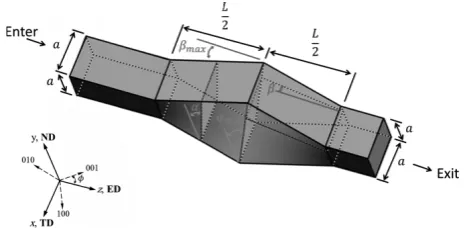
which is based on pressing material through a specially de-signed direct extrusion channel. Figure 1 shows the schemat-ic representation of the SSE channel with a linear die pro-file8). By passing the material through SSE channel the initial
square cross section (entrance plane) of the material changes to a parallelogram with a distortion angle of α. The maximum shear strain applies at the middle of the channel (middle plane) with maximum distortion angle of αmax. Through the
second half of the SSE channel, the distortion angle decreases gradually and finally the materials comes back to its initial square cross section at the exit of the SSE channel (exit plane). So a shear strain of tan(αmax) is applied to the material
in each half of the channel. Therefore, the total effective strain of 2 tan(√αmax)
3 is achieved after one pass of SSE. The length of the SSE channel and subsequently the strain rate of the pro-cess depend on the maximum inclination angle (βmax)9). As it
is seen in Fig. 1, each normal direction (ND) plane tilted around ND direction by the inclination angle of β. The βmax is
achieved at the upper and the lower ND planes. The inclina-tion angle has a significant effect on the deformainclina-tion zone, strain rate and the load of the process8,9). Therefore, by
chang-ing the inclination angle it is possible to change the strain rate of the process without change of the total amount of strain.
The ability to apply the strain gradually to the materials made the SSE process a good candidate to impose a high amount of strain into the difficult to work materials like magnesium al-loys and twinning induced plasticity (TWIP) steels10,11) at
ambient temperature.
Although there are some reports on the microstructural and mechanical behavior of pure aluminum7,12), TWIP steel13)
and pure magnesium10) after SSE processing, there is not any
report about the texture investigation of the samples during and after SSE process. In this work the texture of the pure copper during and after one pass of SSE has been investigated by electron back-scattering diffraction (EBSD). For this rea-son, samples were taken out from the die during the deforma-tion.
2. Experimental Procedure
An SSE die with a square cross section with αmax and βmax
of 45º and 22.2º respectively, and a side length of 10 mm was designed and constructed. In this case the theoretical strain for each pass is 1.155. The length of the deformation channel (deformation zone) corresponds to the maximum inclination angle (βmax) by9)
L= atanαmax
tanβmax (1)
where a is the side of the square cross section in the entrance *
Corresponding author, E-mail: [email protected]
Fig. 1 The SSE die geometry and the coordinate system employed in this paper.
Materials Transactions, Vol. 57, No. 9 (2016) pp. 1386 to 1391
[image:1.595.310.543.297.415.2]of the channel and L is the length of the deformation channel. Using eq. (1), the length of deformation channel is 25 mm. It is possible to extract the samples during the SSE process by stopping the process and open the die as it is a two part die. Copper billets of commercial purity with a dimension of 10 mm × 10 mm × 50 mm were machined and annealed for 2 h at 650ºC and then furnace cooled to room temperature as an initial material. To reduce the friction between sample and tools, samples wrapped with Teflon tape and silicon sprayed. A screw press with a ram speed of 0.2 mm/Sec was used for SSE processing.
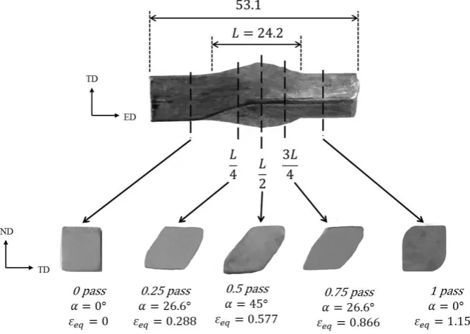
To investigate the texture of samples during the SSE pro-cess, samples were extracted from the SSE die during the de-formation. As it is seen in Fig. 2, the sample was cut during the deformation after passing through the deformation chan-nel in the distance of 0.25L, 0.5L and 0.75L as well as before and after the deformation channel. Initial annealed, 0.25L, 0.5L, 0.75L and first pass samples were named as 0 pass, 0.25 pass, 0.5 pass, 0.75 pass and 1 pass samples respectively in this article.
For the texture investigations, electron back-scattering dif-fraction (EBSD) was used. After the standard metallogra-phies procedure, the obtained surfaces were electrically pol-ished in a solution of 30 Vol. % ethanol-70 Vol. % ml phosphoric acid with a DC voltage of 2.5 V for 15 minutes at room temperature. EBSD observations were performed by a JEOL 7001F scanning electron microscope (FE-SEM) equipped with a field emission gun operating at 20 kV. The JTEX software14) was used for the texture investigations.
For each sample, the area of about 1 × 1.2 mm2 in the
cen-ter was investigated by EBSD with the pixel size of 5.2 μm2.
The grain size for the 0 and 1 pass samples are about 20 and 6 μm respectively. The approximate number of the grains in-cluded in the EBSD analysis is 1110, 4980, 6650, 5250 and 6270 for 0, 0.25, 0.5, 0.75 and 1 pass samples, respectively.
3. Result and Discussions
The equivalent strain (εeq) in an SSE section with a
distor-tion angle of α calculated by8)
εeq= 2x tan(αmax)
L√3 (2)
where x is the distance from the entrance of the SSE channel and L is the total length of the SSE channel (see Fig. 1). The distortion angle for 0, 0.25, 0.5, 0.75 and 1 pass samples is 0 , 26.6 , 45 , 26.6 and 0 respectively; therefore using eq. (2) the corresponding theoretical strain for the 0, the 0.25, the 0.5, the 0.75 and the 1 pass samples is 0, 0.288, 0.577, 0.866 and 1.155 respectively. As it can be seen in Fig. 2 the shear strain applied gradually from the entrance to the middle of the deformation channel and the maximum shear happens in the 0.5 pass sample. After that, the shear direction is reversed and the sample is expected to become to the original square cross section at the exit. However, as it illustrated in Fig. 2, as a result of the lack of back pressure the cross section of 1 pass sample is not completely square7,8). This is the reason of the
change in the length of the sample from 50 mm to 53.1 mm after a pass of SSE which means an elongation in the length of 6.2%.
As it is illustrated in Fig. 1, during the deformation chan-nel, a sample extruded in the SSE die is distorted on the ED-plane in TD-direction (namely, shear happens in ND-ED-plane)9).
Therefore, it is legitimate to think that SSE textures would be similar to that of simple shear textures. The most important ideal orientations in simple shear are distributed along the two fibers with a crystallographic slip direction parallel to the shear direction and a crystallographic slip plane parallel to the shear plane, respectively15–17). These fibers are {hkl}〈110〉
[image:2.595.128.462.72.309.2]shear fibers are given in Table 118). In this study, the textures
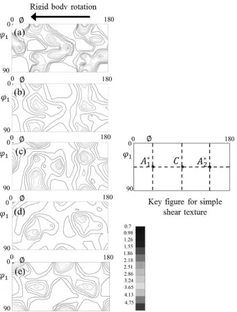
are represented in the TD-ND-ED reference system and the orientations are specified in terms of the {hkl} plane parallel to the ND-plane and the 〈uvw〉 direction parallel to the TD-di-rection (See Fig. 1). The evolution of component of simple shear texture in the first section of the orientation distribution function (ODF) during one pass of SSE is shown in Fig. 3. In the initial stage of deformation (Fig. 3(b)), the A∗
1 and A∗2 components appeared from a fully annealed texture (Fig. 3(a)). In the 0.5 pass sample, all three ideal components appearing in this section are well developed (see Fig. 3(c)). The A∗
1 and A∗2 components show some fiber nature in both 0.25 and 0.5 pass samples. In the second half of deformation channel, by reversing the shear direction the C component eliminates and the major components are A∗
1 and A∗2. Howev-er, the intensity of A∗
1 and A∗2 components of 0.75 pass sample (Fig. 3(d)) is lower than the 0.5 pass sample (Fig. 3(c)). The crystallographic orientation in the second half of the channel
Table 1 Main ideal orientations in simple shear deformation of fcc materi-als18).
Notation {hkl uvw Euler angles ( )
ϕ1 ∅ ϕ2
A∗
1 (111)[¯1¯12] 35.26/215.26 45 0/90
125.26 90 45
A∗
2 (111)[11¯2] 144.74 45 0/90
54.74/234.74 90 45
A (1¯11)[110] 0 35.26 45
¯A (¯11¯1)[¯1¯10] 180 35.26 45
B (1¯12)[110] 0/120/240 54.74 45
¯B (¯11¯2)[¯1¯10] 60/180 54.74 45
C {001 110 90/270 45 0/90
0/180 90 45
Fig. 3 The φ2 = 0 section of the ODF of (a) the 0 pass, (b) the 0.25 pass, (c) the 0.5 pass, (d) the 0.75 pass and (e) the 1 pass, pure copper samples during SSE.
[image:3.595.304.549.93.256.2] [image:3.595.129.471.313.762.2]would resemble the initial texture as a result of the reversing the shear through the second half of the SSE channel. As shown in Fig. 3(e) after the exit of the channel (1 pass sam-ple) still the A∗
1 and A∗2 components are the major components,
their intensity, however, is higher in the 1 pass compared to 0.75 pass. Compare Fig. 3(e) with Fig. 3(b) it is known that the texture of the 1 pass sample is more similar to the 0.25 pass sample. Therefore, although resemblance of the textures to the simple shear textures reduces by distancing from the middle plane but the simple shear textures are still the major components after the exit of the channel which means that the initial textures are not recovered completely. The same trend was reported for the ECAP processing by route C19) which is
considered the reversal route.
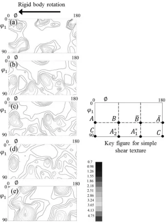
Figure 4 displays the φ2 = 45◦ section of the ODF. For all
the samples the main components are A, A∗
2 and ¯B
compo-nents. For the 0.5 pass sample the C component still has the highest intensity. The 0.5 pass sample has the highest
intensi-ty of the components (Fig. 4(c)). Same as the first section of ODF, after a pass of SSE, some components of simple shear remains with lower intensity (see Fig. 4(e)). In this section the highest intensity component is A∗
2 after a pass of SSE. For
both, φ2 = 0◦ and φ2 = 45◦ , the simple shear textures are not so
strong even for the 0.5 pass sample; the result comes from the fact that the amount of shear in the middle plane (0.5 pass) is 1 which is not so high20).
For all the samples, the ¯B and A∗
2 components rotate by
about 10 in the sense of rigid body rotation with respect to the ideal orientation. The A and A∗
1 components rotate same as A∗
2 but in a reverse sense. The rotation in the sense opposite to
rigid body motion is the characteristics of simple shear while the rotation in the sense of the rigid body motion is the char-acteristics of the ECAP process20). The rigid body rotation is
inherent in simple shear and it affect the texture of the mate-rials based on the matemate-rials slip systems and consequently its strain rate sensitivity17,21).
[image:4.595.128.469.67.523.2]Figure 5 shows the volume fraction of each simple shear components of textures for all the samples. As it is seen the 0.25 and the 0.5 pass samples has the strongest textures and after the reversing the shear strain the simple shear textures reduce gradually. All the components of shear strain are de-veloped well for the 0.25 and the 0.5 pass samples while for the 1 pass sample only some of the components are seen. The major texture component for 0.25, 0.5, 0.75 and 1 pass sam-ples are the A∗
2, C, A∗1 and A∗2 respectively. The distribution of
texture after a pass of SSE is similar to 0.25 pass sample but with lower intensity. Also, it is interesting and unexpected that the intensity of simple shear texture is higher in the 1 pass sample than the 0.75 pass sample but as it is expectable its lower than 0.5 pass sample.
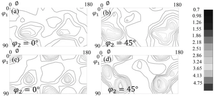
The φ2 = 0◦ and φ2 = 45◦ sections of ODF on ND and TD
planes of the 1 pass sample are shown in Fig. 6. Comparing the ODF sections of the ED-plane with the ND and the TD planes it can be concluded that the textures on ND plane is closer to the ideal orientation of simple shear as it was expect-ed. The major texture components for ND-plane are A, A∗
1, A¯
and A∗
1 (see Fig. 6(a) and (b)). As it is seen in Fig. 6(c) and (d)
the A and A¯ components are the strongest shear components on TD-plane. Therefore, the orientation of TD plane is more similar to initial texture and the simple shear textures are not developed well for this plane. For the ND and the TD planes the major component is the A¯ component while it is the A∗
2 for
the ED- plane.
4. Conclusion
In the present work the texture evolution of pure copper during and after the first pass of simple shear extrusion tech-nique was investigated by EBSD observations. For this rea-son, samples were taken out from the SSE die during the pro-cess. From the beginning to the middle of the deformation channel, the simple shear textures were formed gradually and the strongest simple shear textures were observed on the 0.5 pass sample. As a result of the shear reversal, the degree of the simple shear textures decreases gradually with the dis-tance from the middle plane but the simple shear textures were still the major components after the exit of the channel; this means that the initial textures were not recovered com-pletely. After a single pass of SSE, the most and the least sim-ilarity to the simple shear textures were seen in the ED and the TD planes, respectively. The major orientation compo-nents after first pass were the A∗
2, A¯ and A¯ on ED, ND and TD
planes, respectively. However, the major component for the 0.5 pass sample was the C component.
Acknowledgment
E. Bagherpour would like to thank the financial support of the Iranian Ministry of Science, Research and Technology, Semnan University, Shiraz University and Doshisha Univer-sity.
REFERENCES
1) I.J. Beyerlein and L.S. Tóth: Prog. Mater. Sci. 54 (2009) 427–510.
2) S. Li, I.J. Beyerlein, D.J. Alexander and S.C. Vogel: Acta Mater. 53 (2005) 2111–2125.
3) M. Hafok and R. Pippan: Philos. Mag. 88 (2008) 1857–1877.
4) A.P. Zhilyaev, B.K. Kim, J.A. Szpunar, M.D. Baró and T.G. Langdon:
Mater. Sci. Eng. A 391 (2005) 377–389.
5) N. Tsuji, R. Ueji and Y. Minamino: Scr. Mater. 47 (2002) 69–76.
6) N. Kamikawa, T. Sakai and N. Tsuji: Acta Mater. 55 (2007) 5873–5888.
7) N. Pardis and R. Ebrahimi: Mater. Sci. Eng. A 527 (2009) 355–360.
8) E. Bagherpour, F. Qods and R. Ebrahimi: IOP Conference Series: Ma-ter. Sci. Eng. 63 (2014) 012046.
9) E. Bagherpour, R. Ebrahimi and F. Qods: Mater. Des. 83 (2015) 368– 376.
Fig. 5 Volume fraction of main ideal orientation components in simple shear deformation for the 0.25, the 0.5, the 0.75 and the 1 pass copper samples processed by SSE technique.
Fig. 6 The φ2 = 0 section of the ODF of (a) the ND-plane and (c) the TD-plane, the φ2 = 45 sections of ODF of (b) the ND-plane and (d) the TD-plane of pure copper after a single pass of SSE processing.
[image:5.595.125.469.70.224.2] [image:5.595.56.285.276.406.2]10) N.B. Tork, N. Pardis and R. Ebrahimi: Mater. Sci. Eng. A 560 (2013) 34–39.
11) E. Bagherpour, M. Reihanian and R. Ebrahimi: Mater. Des. 36 (2012) 391–395.
12) N. Pardis and R. Ebrahimi: Mater. Sci. Eng. A 527 (2010) 6153–6156.
13) E. Bagherpour, M. Reihanian and R. Ebrahimi: Mater. Des. 40 (2012) 262–267.
14) J. -J. Fundenberger, B. Beauser: Jtext-Software for Texture Analysis. Universite de lorraine-Metz, 2015, http://jtex-software.eu.
15) G.R. Canova, U.F. Kocks and J.J. Jonas: Acta Metall. 32 (1984) 211– 226.
16) F. Montheillet, M. Cohen and J.J. Jonas: Acta Metall. 32 (1984) 2077– 2089.
17) L.S. Toth, P. Gilormini and J.J. Jonas: Acta Metall. 36 (1988) 3077– 3091.
18) S. Li, I.J. Beyerlein and M.A.M. Bourke: Mater. Sci. Eng. A 394 (2005) 66–77.
19) S. Li, I.J. Beyerlein and C.T. Necker: Acta Mater. 54 (2006) 1397– 1408.
20) L.S. Tóth: Adv. Eng. Mater. 5 (2003) 308–316.