3Fe-2Mo alloy have been studied in this work. The results show that the Si addition decreases the volume fraction of¢phase and precipitates particulate Ti5Si3phase. At the same time, the Si addition improves the high temperature strength of the Ti-45Al-3Fe-2Mo alloy for about
200 MPa at 800°C and decreases the creep strain for about 35%at 800°C under an applied stress of 150 MPa. The decrease in volume fraction of
¢phase and precipitation of Ti5Si3particles are believed to be the dominant mechanisms for the improvement of the high temperature properties
of the Si-doped TiAl alloy. [doi:10.2320/matertrans.M2015355]
(Received September 16, 2015; Accepted December 14, 2015; Published February 5, 2016)
Keywords: TiAl alloy, silicon addition, microstructure, high temperature compressive property, high temperature creep property
1. Introductions
Titanium aluminide (TiAl) is a promising light-weight structural material which can withstand temperatures up to 900°C and may satisfy the demand for weight reduction and higher engine efficiencies in automotive, aerospace, and energy industries.1,2)Although remarkable progress has been made, TiAl alloy has not yet been widely applied because of its brittleness and limited workability. One way to improve the workability of TiAl alloys is to add alloying elements to form ¢ phase at elevated temperatures.3) The disordered
¢ phase with bcc lattice provides a sufficient number of independent slip systems and is softer than the ¡2 and £ phases. Thus, it may improve the deformability of TiAl alloys at an elevated temperature. Several researchers47) have demonstrated that improvements in hot workability can be achieved by stabilizing the¢phase through alloying with Nb, Fe, Mo, or other elements. In our previous works,810)a new Ti-45Al-3Fe-2Mo at%alloy with a volume fraction of the¢ phase higher than 25%was designed. Good workability under near conventional condition and improved low-temperature superplastic properties were obtained in this alloy.
The crucial requirements for TiAl alloys as a structural material are good tensile/compressive strength and high creep strength at high temperatures. The introduction of the ¢ phase may deteriorate the tensile/compressive and creep properties since the ¢phase is soft at elevated temperatures. One way to solve this dilemma is to eliminate the¢phase by subsequent heat treatments after hot working,11) but it is difficult to eliminate the¢phase completely since it usually contains stabilizing elements. Addition of interstitial ele-ments, such as Si, is another way to increase the high temperature properties of TiAl alloys. Some works have demonstrated that the addition of Si can modify the microstructures and improve the high temperature properties of £-TiAl alloys.12,13) However, for the ¢ stabilized TiAl alloys, the effects of Si on the microstructures and the high
temperature properties are still unclear. In the present study, the effects of Si addition on the microstructures, the high temperature compressive properties and high temperature creep properties of the ¢-stabilized Ti-45Al-3Fe-2Mo alloy have been studied, and the deformation mechanisms during hot compression and creep are also discussed.
2. Experimental
TiAl-based alloys with compositions of Ti-45Al-3Fe-2Mo-xSi (x=0, 0.3, 0.5 and 1.0, at%) were prepared by a vacuum arc melting method. To ensure composition uniformity, the alloys were remelted at least 4 times. The ingots were then homogenized at 1200°C for 24 h and 900°C for 2 h, followed by air cooling. Samples for hot compression and creep tests were machined from the homogenized ingots. The hot compression samples have a diameter of 8 mm and a height of 12 mm, and the creep samples have a diameter of 6 mm and a length of 30 mm in the gauge area. Compression tests were conducted at temperatures of 800°C and strain rate of 10¹2s¹1 on an Instron 3369 machine. Creep tests were carried out at 800°C for 300 h under a constant loading of 150250 MPa on a MTS-GWT 2105 creep tester. The microstructures of the samples before and after deformation were observed by Field Emission Scanning Electron Microscope (FE-SEM, FEI NOVA NANOSEM 230) and Transmission Electron Micro-scope (TEM, JEOL 2100F). The specimens for SEM ob-servation were electrolytically polished by using 30 ml nitric acid and 70 ml methanol solution, and the TEM specimens were prepared by twin jet-polishing in an electrolyte solution containing 5% volume of perchloric acid, 35% volume of butanol and 60 vol%of methanol at¹30°C and 20 V.
3. Results and Discussions
3.1 Effects of Si on the microstructure
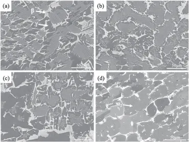
as shown in Fig. 1(a). The average grain size of the Ti-45Al-3Fe-2Mo alloy is about 35 µm and the volume fraction of the ¢phase is about 15.4%. With increasing the Si content, the average grain size and the volume fraction of ¡2 phase increase, while the volume fraction of ¢ phase and the lamellar spacing of the colonies decrease. When the content of Si increases to 1.0 at%(Fig. 1(d)), it is hard to observe the lamellar structure and the microstructrue contains£phase,¡2 phase and residual¢phase.
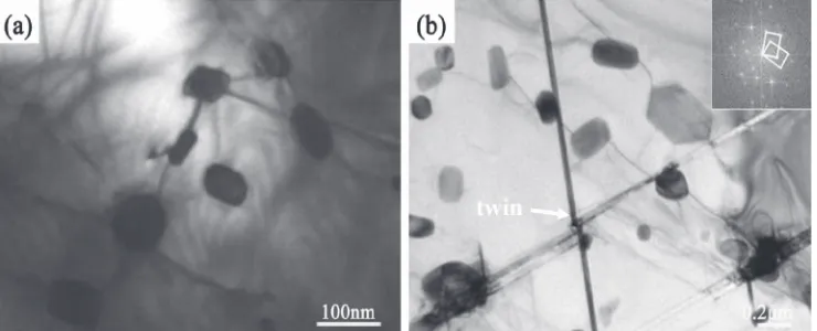
Figures 2(a)(c) show the TEM images of the Ti-45Al-3Fe-2Mo-xSi alloys after homogenization. Some round-shaped precipitates disperse in the TiAl matrix. According to the EDS analysis, the precipitates are rich in Ti (47.6 at%) and Si (32.5 at%), while poor in Fe (1.6 at%) and Mo (1.5 at%). Kim et al.14) studied the Ti-Al-Si ternary phase diagram and reported that the solubility of silicon in the £phase is lower than 0.5%below 1273 K, and the Ti5Si3-type titanium silicate forms in the alloys containing over 0.5%Si.15)Therefore, the precipitates in the present study can be determined to be Ti5Si3 particles. The Si content of the alloys has a great influence on the size of the Ti5Si3precipitates. With an increase in the Si content from 0.3%to 1.0%, the size of the Ti5Si3precipitates increases from about 50 nm to nearly 300 nm. Figures 2(d) and (e) show high resolution images and related FFTs (Fast Fourier Transform) of the Ti-45Al-3Fe-2Mo-0.5Si alloy. The observed position is indicated by an arrow in Fig. 2(b). It indicates that the£phase and Ti5Si3phase have an orientation relationship of ½011£ ==½4223¦, ð111Þ£ ==ð1122Þ¦. Similar result was reported by Zhang et al.16) and Yinet al.17) The Ti5Si3 has a hexagonal D88 structure with lattice parameter
a=0.7461 nm, andc=0.5151 nm.18)
Fig. 1 SEM images (BSE mode) of the Ti-45Al-3Fe-2Mo-xSi alloys: (a) 2Mo, (b) 2Mo-0.3Si, (c) Ti-45Al-3Fe-2Mo-0.5Si and (d) Ti-45Al-3Fe-2Mo-1Si. The white phase, grey phase and dark phase correspond to the¢phase, the¡2and£phase,
respectively.
Fig. 2 TEM bright field images of the Ti-45Al-3Fe-2Mo-xSi alloys deformed at 800°C with strain rate of 10¹2s¹1: (a)
[image:2.595.113.485.70.349.2] [image:2.595.307.548.444.731.2]temperature strength because the bcc ¢ phase is a high temperature soft phase. At the same time, the precipitation of
new grains created by dynamic recrystallization can be observed in the residual¢phases. In the Ti-45Al-3Fe-2Mo-1Si alloy, no lamellar kinking can be observed and the grain boundary¢phases were broken to particles. Figure 5 shows the TEM microstructures of Ti-45Al-3Fe-2Mo-1Si alloy deformed at 800°C with a strain rate of 10¹2s¹1. It indicates that the Ti5Si3 precipitates pin the dislocations (Fig. 5(a)), restrain the movement of dislocation, and cause the second phase dispersion strengthening. At the same time, some Ti5Si3 precipitates react with the twins (Fig. 5(b)) and affect the twin deformation. The dispersion strengthening and the interaction with the twin greatly increase the high temper-ature strength.
[image:3.595.62.276.254.413.2]3.3 Effects of Si on the high temperature creep proper-ties
Figure 6 shows the creep curves of the Ti-45Al-3Fe-2Mo-xSi alloys tested at temperature of 800°C with an applied stress of 150 MPa. At a creep time of 7©105s, the creep
Fig. 3 True stress vs. true strain curves of the Ti-45Al-3Fe-2Mo-xSi alloys deformed at 800°C and strain rate of 10¹2s¹1.
Fig. 4 SEM Microstructures of the Ti-45Al-3Fe-2Mo-xSi alloys deformed at 800°C with strain rate of 10¹2s¹1: (a) Ti-45Al-3Fe-2Mo
[image:3.595.114.484.459.748.2]strain for the Ti-45Al-3Fe-2Mo-0.5Si alloy is about 2.5%, which is about 35%lower than that of the Si-free alloy. The results suggest that the Si-contained alloy has much better creep resistance than the Si-free alloy. Figure 7 shows the relationship between the minimum creep rate and effective stress for the Ti-45Al-3Fe-2Mo-xSi alloys. The stress exponent n can be deduced from the slope of the lines. The nvalue of the Si-free alloy is about 4.2, which suggests that the creep deformation is controlled by the dislocation climb,19)while the value for the Si-contained alloy is about
6.5, which exhibits a characteristic of precipitation hardened alloy. A high stress exponent of the Si-contained alloy suggests the retarding effect of the precipitates on the dislocation migration. The dislocations climb over the Ti5Si3 precipitates and detach around the precipitates.
Figure 8 shows the TEM microstructures of the Ti-45Al-3Fe-2Mo alloys after creep deformation at 800°C. The dislocations form a dislocation wall, as shown in Fig. 8(a), which suggests that the dislocation can move easily. At the same time, some¢phases disperse on the£/¡2interfaces and
Fig. 5 TEM images of the Ti-45Al-3Fe-2Mo-1Si alloy deformed at 800°C with strain rate of 10¹2s¹1: (a) the interaction between the
Ti5Si3particles and the dislocations; (b) the interaction between the Ti5Si3particles and the twins.
Fig. 6 Creep curves of the 2Mo alloy and the Ti-45Al-3Fe-2Mo-0.5Si alloy tested at 800°C and 150 MPa.
Fig. 7 Relationship between the minimum creep rate and effective stress for the Ti-45Al-3Fe-2Mo alloy and Ti-45Al-3Fe-2Mo-0.5Si alloy.
[image:4.595.115.485.72.222.2] [image:4.595.64.278.264.435.2] [image:4.595.319.535.266.430.2] [image:4.595.114.484.480.626.2]act as lubricant for the creep deformation, as shown in Fig. 8(b). Figure 9 shows the TEM images of the Ti-45Al-3Fe-2Mo-0.5Si alloys after creep deformation at 800°C under a stress of 150 MPa. It reveals that somefine precipitates with an average size of 10 nm embedded in the TiAl matrix (Fig. 9(a)), and the dislocations are pinned and tangled together around the fine precipitates. These dislocations are 1/2[110] type dislocations which is determined by Perdrix et al.15) There are also some coarse precipitates with a size of about 100 nm (Fig. 9(b)). The big particles can act as a generation of dislocation due to the high stress concentration in the interface of the matrix and particles. The dislocations bypass the precipitates follows the simple orowan mechan-ism, which can be descripted as:20)
·Or¼2³0ð1:84M¯Þ1=2Gbl ln rb ð1Þ
where·oris the Orowan stress,Mis the Taylor factor,vis the Poisson’s ratio,lis the mean spacing between the particles,r is the mean particle radius,Gis the shear modulus of matrix and b is the length of Burgers vector. For the present TiAl alloys, the constants in eq. (1) can be determined as: M=3,21) v=0.24,21) b=2.83©10¹10m,22) l=10¹7m, r=5©10¹8nm, the mean spacing between the particles (l) and the mean particle radius (r) were determined from the TEM observations. Therefore, an Orowan stress in the present alloy can be calculated to be 0.4 MPa. The Orowan stress provides dislocation motion resistance and thus improves the creep properties.
4. Conclusions
(1) The Si addition refines the lamellar spacing, decreases the volume fraction of ¢ phase and precipitates the Ti5Si3 particles in the ¢-stabilized Ti-45Al-3Fe-2Mo alloy. The size of the precipitates increases with the increase of the Si content.
(2) The 0.5% Si addition improves the high temperature strength of the Ti-45Al-3Fe-2Mo alloy for about 200 MPa at 800°C and decreases the creep strain for about 35%at 800°C under an applied stress of 150 MPa. (3) Decrease in volume fraction of¢phase, reducing of the lamellar spacing and precipitation of Ti5Si3particles are believed to be the dominant mechanisms for the
improvement of the high temperature properties of the Si-doped TiAl alloy.
Acknoledgement
The authors would like to thank financial supports of National Key Fundamental Research and Development Project of China (2014CB644002), National Natural Science Foundation of China (51301203) and National Science Foundation for Post-doctoral Scientists of China (2014M551827).
REFERENCES
1) H. Clemens and H. Kestler:Adv. Eng. Mater.2(2000) 551570.
2) X. H. Wu:Intermetallics14(2006) 11141122.
3) R. M. Imayev, V. M. Imayev, M. Oehring and F. Appel:Intermetallics
15(2007) 451460.
4) F. Appel, M. Oehring and J. D. H. Paul:Adv. Eng. Mater.8(2006) 371376.
5) T. T. Cheng and M. H. Loretto:Acta Mater.46(1998) 48014819.
6) M. Takeyama and S. Kobayashi:Intermetallics13(2005) 993999.
7) V. Imayev, R. Imayev, T. Khismatullin, V. Guther, W. Beck and H. J. Fecht:Scr Mater.57(2007) 193196.
8) B. Liu, Y. Liu, C. Z. Qiu, C. X. Zhou, J. B. Li, H. Z. Li and Y. H. He:
J. Alloys Comp.640(2015) 298304.
9) C. Z. Qiu, Y. Liu, L. Huang, W. Zhang, B. Liu and B. Lu:Trans. Nonferr. Metal. Soc. China22(2012) 521527.
10) C. Z. Qiu, Y. Liu, W. Zhang, B. Liu and X. P. Liang:Intermetallics27
(2012) 4651.
11) H. L. Zhu, D. Y. Seo and K. Maruyama:JOM62(2010) 6669.
12) S. Tsuyama, S. Mitao and K. N. Minakawa:Mater. Sci. Eng. A153
(1992) 451456.
13) T. Noda, M. Okabe, S. Isobea and M. Sayashi:Mater. Sci. Eng. A192/ 193(1995) 774779.
14) Y. W. Kim:JOM41(1989) 2430.
15) F. Perdrix, M. F. Trichet, J. L. Bonnentien, M. Cornet and J. Bigot:
Intermetallics9(2001) 147155.
16) H. Zhang, L. L. He and H. Q. Ye:Mater. Sci. Eng. A360(2003) 415 419.
17) W. M. Yin and V. Lupinc:Scr. Mater.37(1997) 211217.
18) A. Menand, A. Huguet and A. Nérac-Partaix:Acta Mater.44(1996) 47294737.
19) J. G. Wang and T. G. Nieh:Intermetallics8(2000) 737748.
20) K. Ma, H. M. Wen, T. Hu, T. D. Topping, D. Isheim, D. N. Seidman, J. Enrique and M. S. Julie:Acta Mater.62(2014) 141155.
21) R. E. Stoller and S. J. Zinkle:J. Nuclear Mater.283287(2000) 349 352.
22) G. Q. Chen, B. G. Zhang, W. Liu, J. C. Feng and Y. L. Liu: Trans. China Weld. Inst.31(2010) 15.
[image:5.595.115.484.69.223.2]