Half-Metallic Properties and Stability of Ferromagnetic State
in the Full-Heusler Alloys (Fe
xRu
1 x)
2CrSi (
0
x
1
)
Sou Mizutani
1;*1, Shoji Ishida
2, Sinpei Fujii
2and Setsuro Asano
3;*21
The Graduate School of Science and Engineering, Kagoshima University, Kagoshima 890-0065, Japan
2Department of Physics, Faculty of Science, Kagoshima University, Kagoshima 890-0065, Japan 3Institute of Physics, College of Arts and Sciences, University of Tokyo, Tokyo 153-0041, Japan
We investigate the half-metallic properties and the stability of the ferromagnetic state in the alloys (FexRu1x)2CrSi (0x1) with
orderly and disorderly atomic arrangement based on the Heusler structure. It is predicted from the electronic structures that the ordered alloys are half-metals in the range of 1=3<x<3=4and ferromagnets with high spin polarization in the range of 3=4x1. However, in the ferromagnetic state, the atomic arrangement with the Fe–Cr disorder tends to be energetically more favorable than the orderly arrangement, and the Fe–Cr disorder decreases the spin polarization of the ordered alloys. This is attributed to the fact that occupation of Cr sites by Fe destroys the gap near the Fermi energy in the minority spin state. But, because the Fe–Cr disorder shows a tendency to keep the spin polarization high asx increases, it is deduced that (FexRu1x)2CrSi are materials with high spin polarization ifxis high.
(Received July 19, 2005; Accepted August 26, 2005; Published January 15, 2006)
Keywords: half-metal, electronic structure, atomic disorder, stability of ferromagnetic state, iron–ruthenium–chromium–silicon
1. Introduction
A half-metal (HM) is metallic in one spin band, while is semiconducting in the other spin band, that is, it makes the spin polarization (P) complete (100%). This character is considered to be very useful in spintronics, such as a tunneling magnetoresistance (TMR) device because it has been expected to get huge magnetoresistive effect in TMR devices. For example, in the film with three layers where a non-magnetic layer is sandwiched between two magnetic layers, the TMR is represented as
TMR¼ 2P1P2
1P1P2 ;
wherePnis the spin polarization of the n-th magnetic layer.1)
If the magnetic layers are HMs, the TMR becomes infinite. HMs have been studied more than 20 years since De Groot
et al. predicted those materials in the half-Heusler alloys NiMnSb and PtMnSb.2)Ishidaet al.have searched various HMs in not only the half-Heusler alloys but also the full-Heusler alloys (X2YZ) and the results have been summarized
in Ref. 3). They have predicted that Co2MnZ (Z = Si, Ge)
alloys are HMs as one example of those,4)but the presence of the disorder between Co and Mn in those alloys has been proved experimentally by Raphael et al. and band calcu-lations by Picozzi et al. have proposed that Co anti-sites destroy the half-metallicity.5–8) Inomataet al.have
demon-strated that a spin valve type tunneling junction with a layer of Co2(Cr0:6Fe0:4)Al has large TMR of 16% at room
temperature and 26.5% at 5 K.9) However, they have also
shown the existence of the disorder between Al and Y (Y = Cr, Fe), that is, shown that the Co2(Cr0:6Fe0:4)Al
film has the B2 structure, and Miura et al. have predicted from band calculations that the spin polarization of
Co2(Cr1xFex)Al with the disordered B2 structure is a little
smaller than that of the L21structure.10)Using a full-potential ab initio technique, Galanakis has suggested that the (001) surfaces of Co2MnGe and Co2MnSi lose the half-metallic
character, while the CrAl-terminated (001) surface of Co2CrAl does not lose it very much, showing the spin
polarization of about 84%.11)He has explained that the high spin polarization for the surface of Co2CrAl is attributed to
not only maintenance of the pseudogap at the Fermi energy (EF) in the minority spin state but also the very high density
of states (DOS) of Cr and Co at theEFin the majority spin
state.
Thus, the high spin polarization expected from the theoretically predicted HMs has not been obtained exper-imentally. The fact may be considered to be due to the various problems, such as atomic disorder and effect of surface. However, acquisition of the materials with high spin polarization or HMs may be possible if we can find the materials, like Co2CrAl, which possess very highDOSat the
EFin the majority spin state and a pseudogap or gap at theEF
in the minority spin state.12)In other words, the full-Heusler alloys X2CrZ in which Cr occupy the Y sites in X2YZ may be
the candidates as those materials.
In this study, we pay attention to the full-Heusler alloys (FexRu1x)2CrSi (0x1), and investigate the effect of
the atomic disorder on the half-metallic properties of the alloy system. However, Ru2CrSi may be antiferromagnetic
because it has been reported experimentally and theoretically that Ru2MnSi is antiferromagnetic.13,14) Therefore, the
stability of the ferromagnetic state is also examined in (FexRu1x)2CrSi where Fe are partially or totally substituted
for Ru.
2. Methods of Calculations
Band calculations are carried out self consistently by the linear muffin tin orbital (LMTO) method and the atomic sphere approximation (ASA).15) The exchange correlation
*1Graduate Student, Kagoshima University
*2National Center for University Entrance Examinations, Tokyo 153-8501,
Japan
potential is treated within the framework of the local-spin-density (LSD) approximation.16)
The unit cell of the L21 structure is treated as a trigonal
structure because of consideration for atomic disorder with the various levels and a small amount of substitution of Fe for Ru in (FexRu1x)2CrSi. The crystal structure is shown in
Fig. 1. The theoretical values of the lattice constant for the ordered alloys (FexRu1x)2CrSi in the ferromagnetic state are
shown in Table 1. The lattice constant a of the trigonal structure adopted in the band calculations is pffiffiffi2 times as large as that of the cubic structure.
About the disorder type of (FexRu1x)2CrSi, we consider
three types of disorder, Cr–Si, X–Cr and X–Si (X = Fe, Ru). The molecular formulae of the Cr–Si, X–Cr and X–Si types of disorder are described as (FexRu1x)2(Cr1ySiy)(Si1yCry),
((Fexy0=2Cry0=2)(Ru1xy00=2Cry00=2))2(Cr1y(Fey0Ruy00))Si and
((Fexy0=2Siy0=2)(Ru1xy00=2Siy00=2))2Cr(Si1y(Fey0Ruy00)),
res-pectively, wherey(¼y0þy00) is the ratio of Cr (Si) occupying anti-sites to the total number of Cr (Si). In this paper, yis defined as the disorder level in each type of disorder, andy0
andy00are done as the disorder levels between Fe and Cr (Si)
and between Ru and Cr (Si), respectively.
To study the stability of the ferromagnetic state in the ordered alloys (FexRu1x)2CrSi, the calculations for the
antiferromagnetic state are also performed. We assume two models, AF1 and AF2, as the magnetic arrangement of the antiferromagnetic state. As shown in Fig. 2, in AF1 the X (Cr,Si) magnetic moments are ferromagnetically coupled on the (001) plane and are antiferromagnetically coupled along the [001] direction. On the other hand, in AF2 the X (Cr,Si) magnetic moments are ferromagnetically coupled on the (111) plane and are antiferromagnetically coupled along the [111] direction as seen in Fig. 1. The unit cell of AF1 is adopted as a triclinic structure.
3. Results of Calculations
3.1 Ordered (FexRu1 x)2CrSi
First, we examine the electronic structures of the ordered alloys (FexRu1x)2CrSi in the ferromagnetic state. The total
DOS of (FexRu1x)2CrSi in the cases of x¼0;1=4;1=2;
3=4;1 and the ordered ferromagnet Co2MnSi is shown in
Figs. 3(a)–(f). The total spin magnetic moment per unit cell and the spin polarization are written in each figure. Convert-ing the moment per unit cell into that per formula unit, the total moment of (FexRu1x)2CrSi is about 2Bin any range
ofxand follows the ruleMt¼Zt24, whereMtis the total
spin magnetic moment per formula unit andZt is the total
number of valence electrons.17) The spin polarization P is
defined asP¼ ðD"D#Þ=ðD"þD#Þ, whereD"andD#are
DOSat theEFin the majority spin state and in the minority
spin state, respectively. From the expression, it is remarked that very highD" approaches Pto 1 even if D# somewhat
appears. Seeing Figs. 3(a)–(f), it is found that the D" of
(FexRu1x)2CrSi is much higher than theD"of Co2MnSi. In
addition, theD"of those alloys shows a tendency to increase
as the Fe concentrationxbecomes higher. To know the cause
AF2 [111]
Cr Si
X (= Fe, Ru)
Fig. 1 The crystal structure of the full-Heusler alloys (FexRu1x)2CrSi
[image:2.595.57.284.73.318.2](left-hand side) and the magnetic arrangement of AF2 (right-hand side).
Table 1 The theoretical values of the lattice constant for the ordered alloys (FexRu1x)2CrSi in the ferromagnetic state. The values in the parentheses
correspond to those of the cubic structure.
Fe concentration,x Lattice constant,a/nm
0 0.840 (0.594)
1/8 0.835 (0.590)
1/4 0.829 (0.586)
3/8 0.823 (0.582)
1/2 0.816 (0.577)
5/8 0.810 (0.573)
11/16 0.808 (0.571)
3/4 0.805 (0.569)
7/8 0.799 (0.565)
1 0.793 (0.561)
X (= Fe, Ru)
Si Cr
[001]
AF1
[image:2.595.303.549.105.239.2] [image:2.595.308.543.106.467.2]of the high D", we investigate the local DOS of
(FexRu1x)2CrSi. The local DOS in the cases of x¼0;
1=2;1 is shown in Figs. 4(a)–(g). From these figures, it is noticed that although the Cr magnetic moment decreases asx increases, the localD" of Cr greatly contributes to the high
D" as we have expected. Also, the local D" of Fe shows
the pretty contribution to it. That is, the high D" of
(FexRu1x)2CrSi is based on that of Cr and its increase with
xis mainly due to that of Fe. As for the half-metallicity in (FexRu1x)2CrSi, theEF is in a gap in the range of0x 11=16, but a small amount of D# exists in 3=4x1.
Therefore, it is inferred in the ferromagnetic state that the ordered alloys (FexRu1x)2CrSi are HMs in0x<3=4and
materials near a HM in3=4x1.
Next, we consider the antiferromagnetic state (AFi; i¼1;
2) in order to study the stability of the ferromagnetic state in the orderly arrangement because it is essential that a HM is ferromagnetic. The relationship between the Fe concentra-tion x and Ei is shown in Fig. 5. Here, Ei is the total
energy difference per formula unit between the antiferroma-getic state and the ferromagnetic state. From this figure, it is found that although Ei is negative for the case of x¼0, E1 andE2are positive fromx¼1=4and fromx¼3=8,
respectively, that is, the ferromagnetic state is more favorable than the antiferromagnetic state in1=3<x1. Organizing the above, it is predicted that the ordered alloys (FexRu1x)2CrSi are HMs in1=3<x<3=4 and are
ferro-magnets with highPin3=4x1. However, the range in which the ferromagnetic state is more stable may change a little because the magnetic arrangement assumed in this study is not necessarily the most stable one in the antiferromagnetic state.
3.2 Disordered (FexRu1 x)2CrSi
As metioned above, it is supposed that very highD"keeps
Phigh even if a small amount ofD#appears for some effect,
so we investigate the effect of the atomic disorder on the half-metallic properties of (FexRu1x)2CrSi. After this, we assume
these alloys ferromagnetic, even in the range ofxwhere the antiferromagnetic state is more favorable.
In (FexRu1x)2CrSi (x¼0;1=4;1=2;3=4;1), the
relation-ship between P and the disorder level y is shown in Figs. 6(a)–(e). Seeing these figures, it is found thatPholds high even though the Cr–Si disorder occurs very much, while the X–Cr and X–Si disorder decreases P as y increases. However, the X–Cr disorder does not degradePas rapidly as the X–Si disorder, and the Fe–Cr disorder tends to keepPasx becomes higher.
Next, we showE, which is the total energy difference per unit cell between each type disordered structure and the
-0.3 0 0.3 0.6
600
400
200
Energy, E / aJ
DOS
/ (aJ
·
unit cell
·
spin)
-1
0
(a) x = 0
-0.6 -0.3 0 0.3
16.00µB µ
16.00µB
(e) x = 1 (b) x = 1/4
P = 100 %
P = 100 %
16.00µB P = 100 %
P = 98 %
(c) x= 1/2
P = 99 %
15.98 B
µ
15.86 B
(d) x = 3/4
400
200
0
400
200
0
(f) P = 100 %
40.00µB
maj. min.
Co2MnSi
Fig. 3 The totalDOSof the ordered alloys (FexRu1x)2CrSi for the cases
ofx= (a) 0, (b) 1/4, (c) 1/2, (d) 3/4, (e) 1 and (f) Co2MnSi. The solid and
the broken lines indicate the majority and the minority spin state, respectively, and the vertical line shows theEF.
1.70 B
(c) Fe 3d
(e) Cr 3d (d) Ru 4d
0.48µB
0.6 30
20
10
Energy, E / aJ
DOS
/ (aJ
·
atom
·
spin)
-1
0
-0.6 -0.3 0 0.3
-0.15µ
µ
B
20
10 0
20
10
0
(b) Cr 3d (a) Ru 4d
(f) Fe 3d
(g) Cr 3d 0.50µB
1.04µB
-0.10µ
µ
B
2.20 B
maj. min.
-0.6 -0.3 0 0.3
20
10
0 (x = 0)
(x = 0) (x = 1/2)
(x = 1/2)
(x = 1/2)
(x = 1) (x = 1)
Fig. 4 The localDOSof the ordered alloys (FexRu1x)2CrSi: (a) Ru 4d
(x¼0), (b) Cr 3d (x¼0), (c) Fe 3d (x¼1=2), (d) Ru 4d (x¼1=2), (e) Cr 3d (x¼1=2), (f) Fe 3d (x¼1), (g) Cr 3d (x¼1). The solid and the broken lines indicate the majority and the minority spin state, respectively, and the vertical line shows theEF.
0 1/4
0.004 aJ
0
Fe concentration, x
∆
Ei
/ aJ
·
f.u.
-1
∆E1
∆E2
1/8 3/8 1/2 5/8 3/4 7/8 1
Fig. 5 The relationship between x and Ei. Ei is the total energy
difference per formula unit between the antiferromagetic state AFi and the ferromagnetic state in the ordered alloys (FexRu1x)2CrSi. The curves
[image:3.595.314.542.74.203.2] [image:3.595.57.282.75.280.2] [image:3.595.57.281.354.619.2]ordered one, as a function of y for (Fe1=2Ru1=2)2CrSi in
Fig. 7. In this figure, we can see that the atomic arrangement with the Fe–Cr disorder is more stable than the orderly arrangement to a certain y (in this case, y¼1=4). The arrangement with the other types of disorder is, on the contrary, more unstable than the orderly one and tends to become more unstable on the whole as y increases.
Tendencies like these are also shown in the other cases of x, and the orderly arrangement is more favorable than any type disorder for Ru2CrSi where the Fe–Cr disorder is
impossible. From these, it is predicted that (FexRu1x)2CrSi
have the Fe–Cr disorder ifxis not 0. Hereafter, we focus on the disorder except the X–Si one in this paper because the atomic arrangement with the X–Si one is very unstable and the probability of the occurrence may be low.
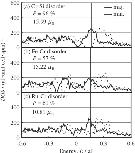
In order to understand the cause of the decrease inP, we examine the DOS of those alloys with the disordered structure. The total DOS of (Fe1=2Ru1=2)2CrSi with each
type disorder in the case ofy¼3=8is shown in Figs. 8(a)– (c). Comparing these figures with Fig. 3(c) corresponding to the orderly arrangement, it is found that the Cr–Si disorder does not destroy the gap near EF in the minority spin state
very much, but the X–Cr disorder destroys it completely, which leads to the decrease in P. In addition, all types of disorder lowers theD"of the orderly arrangement’s case and
this is also the cause of the decrease inP. We study the local DOSin the above cases to research further on the destruction of the gap and the decrease inD". Figures 9(a)–(e) show the
DOS of the atoms occupying anti-sites in the above cases. Comparing these figures with Figs. 4(c)–(e) corresponding to the orderly arrangement, it is remarked that the Cr–Si disorder does not bring about great change in the electronic structures of the atoms occupying anti-sites, while the X–Cr disorder greatly affects them. The DOS of the atoms occupying ordinary sites (not shown in this paper) is not affected in shape very much by the Cr–Si and X–Cr disorder. The destruction of the gap is attributed mainly to X occupying Cr sites, and the causes of the decrease in D"
are chiefly due to the atoms occupying anti-sites, especially Fe occupying Cr sites and Cr occupying X sites. In addition, 100
Spin polarization,
P
/ %
80 90
70
x = 0
x = 1/4
x = 1
x = 1/2
x = 3/4
(a) Cr-Si
(b) Fe-Cr 100
80 100 80 60 40 20 0
60 40 20 0
(e) Ru-Si (c) Ru-Cr
(d) Fe-Si 100
50
0
-50
80 100
60 40 20 0
0 1/4
Disorder level, y
1/8 3/8 1/2
Fig. 6 The relationship between P and y for (FexRu1x)2CrSi (x¼0;
1=4;1=2;3=4;1) with the (a) Cr–Si, (b) Fe–Cr, (c) Ru–Cr, (d) Fe–Si or (e) Ru–Si type disorder.
0 1/4
Disorder level, y
∆
E
/ aJ
·
unit cell
-1
1/8 3/8 1/2
Fe-Cr Ru-Cr Cr-Si
Fe-Si Ru-Si
0 1.5 1.2 0.9
0.6 0.3
-0.3
Fig. 7 Eas a function ofyin the case ofx¼1=2.Eis the total energy difference per unit cell between each type disordered structure and the ordered one.
0.6 600
400
200
Energy, E / aJ
DOS
/ (aJ
·
unit cell
·
spin)
-1
0
(a) Cr-Si disorder
-0.6 -0.3 0 0.3
15.99µB
15.22µB
10.81µB
(b) Fe-Cr disorder
P = 96 %
P = 57 %
P = 61 %
(c) Ru-Cr disorder 400
200
0
400
200
0
maj. min.
Fig. 8 The totalDOSof (Fe1=2Ru1=2)2CrSi with the (a) Cr–Si, (b) Fe–Cr or
[image:4.595.315.540.481.735.2] [image:4.595.55.282.634.746.2]the absolute values of the spin moments of X occupying Cr sites increase and the moments of Cr occupying X sites get to have the opposite direction of those of Cr occupying ordinary sites. Such tendencies on atomic disorder are also obtained in the other cases ofx.
As mentioned above, the spin moments of X and Cr occupying anti-sites dramatically change in the atomic arrangement with the X–Cr disorder, so we investigate the change caused by atomic disorder in the total spin moment. The relationship between the total spin magnetic moment and yfor (Fe1=2Ru1=2)2CrSi is shown in Fig. 10. From this figure,
one can find that although the Fe–Cr disorder decreases gradually the total moment asybecomes higher, the Cr–Si and Fe–Cr disorder almost keeps it. However, the Ru–Cr disorder reduces it considerably. This is due to that Ru at Cr sites do not compensate for the decrement in the moment of Cr at Ru sites (but Fe at Cr sites almost does that of Cr at Fe sites). Regardless of x, all types of disorder shows similar
tendencies on the whole, but the Ru–Cr disorder decreases further the total spin moment in highywhenxis low.
By the way, it is noticed from Figs. 6(c) and 10 that although (Fe1=2(Ru7=16Cr1=16))2(Cr7=8Ru1=8)Si shows
half-metallicity, the total spin moment per formula unit is 1.50
B, that is, (Fe1=2(Ru7=16Cr1=16))2(Cr7=8Ru1=8)Si which is the
same composition as (Fe1=2Ru1=2)2CrSi does not show the
Slater-Pauling behavior.17)This indicates that the total spin magnetic moment of a HM does not necessarily follow the rule Mt¼Zt24 if not only ordered alloys but also
disordered alloys are considered. Such feature is also noticed in other x. Besides, in the case of the disorder between one kind of X (Fe or Ru) and Cr, the above feature appears only for the case of the Ru–Cr disorder, and in the case of the disorder between two kinds of X (Fe and Ru) and Cr, it also appears. Although the results of the latter disorder are not shown in this paper, it tends to keepPhigher than the former disorder.
Lastly, we discuss why the Fe–Cr disorder tends to keepP asxincreases. TheDOSof Fe occupying Cr sites in the case of y¼3=8is shown for the cases ofx¼1=4;1=2;3=4;1in Figs. 11(a)–(d). In these figures, it is found that as x increases, the peak near the EF in the minority spin state
moves to high energy side and theD#becomes lower, which
leads to maintenance ofP. It is supposed that such behavior of the peak near the EF is attributed to that the effect of
neighboring Ru becomes smaller asxincreases. In the Ru–Cr disorder as well as the Fe–Cr disorder, it is considered thatP is easy to decrease inx>0[Fig. 6(c)] because of the effect of neighboring Fe.
Thus, highPis easy to hold in the atomic arrangement with X–Cr disorder ifxis 0 or 1. Considering the stability of the ferromagnetic state in the ordered alloys (FexRu1x)2CrSi,
Fe2CrSi is regarded as the best candidate of materials with
high P. However, the partial substitution of Ru for Fe in Fe2CrSi shows the following merit. Figure 12 shows the
disorder level ywhere the total energy of (FexRu1x)2CrSi
with the Fe–Cr disorder becomes lowest in eachx. From this figure, it is remarked that Ru have the effect to restrain the Fe– Cr disorder. Therefore, taking the above into consideration, it is predict that (FexRu1x)2CrSi with highxshow highP.
-0.3 0 0.3 0.6
Energy, E / aJ
-0.6 -0.3 0 0.3
(c) Cr 3d
(e) Cr 3d (d) Ru 4d
20
10
DOS
/ (aJ
·
atom
·
spin)
-1
0
(b) Fe 3d
(a) Cr 3d
0.60 B
1.21 B
2.58µ µ
µ
µ µ
B -0.61 B
-0.49 B
maj. min.
30
20
10
30
20
10
0
Fig. 9 TheDOS of the atoms occupying anti-sites in (Fe1=2Ru1=2)2CrSi
with each type disorder for the case ofy¼3=8: (a) Cr 3d at Si sites (Cr–Si disorder), (b) Fe 3d at Cr sites (Fe–Cr disorder), (c) Cr 3d at Fe sites (Fe– Cr disorder), (d) Ru 4d at Cr sites (Ru–Cr disorder), (e) Cr 3d at Ru sites (Ru–Cr disorder). The solid and the broken lines indicate the majority and the minority spin state, respectively, and the vertical line shows theEF.
0 1/4
Disorder level, y
1/8 3/8 1/2
Fe-Cr Ru-Cr Cr-Si
Total spin moment /
B
·
unit cell
-1
16
14
12
10
2.00
1.75
1.50
1.25
Total spin moment /
B·
f.u.
-1
µ
[image:5.595.58.281.76.281.2]µ
Fig. 10 The relationship between total spin magnetic moment andyfor (Fe1=2Ru1=2)2CrSi with the Cr–Si (triangle), Fe–Cr (closed square) or Ru–
Cr (open square) type disorder.
-0.3 0 0.3 0.6
Energy, E / aJ
-0.6 -0.3 0 0.3
(c) x = 3/4
(d) x = 1 (b) x = 1/2
30
20
10
DOS
/ (aJ
·
atom
·
spin)
-1
0
(a) x = 1/4
2.54µB 2.64µB
2.62µB
2.58µB
maj. min.
20
10
[image:5.595.313.542.76.227.2]0
Fig. 11 TheDOSof Fe 3d at Cr sites in (FexRu1x)2CrSi with the Fe–Cr
[image:5.595.56.282.377.512.2]4. Summary
We have investigated the half-metallic properties and the stability of the ferromagnetic state, by means of first-principle calculations, in the alloys (FexRu1x)2CrSi (0
x1) with the orderly and disorderly arrangement based on the L21structure. From the results, it has been found that the
ordered alloys are HMs in0x<3=4and materials near a HM in 3=4x1 if those are ferromagnetic. And the results have shown that the ferromagnetic state is energeti-cally more stable than the antiferromagnetic state in
1=3<x1. That is, it has been predicted that the ordered alloys are HMs in1=3<x<3=4and ferromagnets with high P in3=4x1. However, in the ferromagnetic state, the atomic arrangement with the Fe–Cr disorder tends to be energetically more favorable than the orderly arrangement, but the other type disorder to be not. In addition, the Fe–Cr disorder decreases P of the ordered alloys and this is attributed to that Fe occupying Cr sites destroy the gap near the EF in the minority spin state. But, the Fe–Cr disorder
tends to keepPhigh asxincreases and to be restrained asx decreases. Therefore, we conclude that (FexRu1x)2CrSi will
be promising materials in spintronics ifxis high.
Acknowledgment
We are most grateful to Assistant Professor Masahiko Hiroi at Kagoshima University for giving us valuable information.
REFERENCES
1) M. Julliere: Phys. Lett. A54(1975) 225–226.
2) R. A. de Groot, F. M. Mueller, P. G. van Engen and K. H. J. Buschow: Phys. Rev. Lett.50(1983) 2024–2027.
3) S. Ishida:Advance in Condensed Matter and Materials Research4, ed. by Francios Gerard, (Nova Science Publishers Inc., New York, 2003) pp. 149–178.
4) S. Ishida, S. Fujii, S. Kashiwagi and S. Asano: J. Phys. Soc. Jpn.64
(1995) 2152–2157.
5) M. P. Raphael, B. Ravel, M. A. Willard, S. F. Cheng, B. N. Das, R. M. Stroud, K. M. Bussmann, J. H. Claassen and V. G. Harris: Appl. Phys. Lett.79(2001) 4396–4398.
6) M. P. Raphael, B. Ravel, Q. Huang, M. A. Willard, S. F. Cheng, B. N. Das, R. M. Stroud, K. M. Bussmann, J. H. Claassen and V. G. Harris: Phys. Rev. B66(2002) 104429.
7) B. Ravel, J. O. Cross, M. P. Raphael, V. G. Harris, R. Ramesh and V. Saraf: Appl. Phys. Lett.81(2002) 2812–2814.
8) S. Picozzi, A. Continenza and A. J. Freeman: Phys. Rev. B69(2004) 094423.
9) K. Inomata, S. Okamura, R. Goto and N. Tezuka: Jpn. J. Appl. Phys.42
(2003) L419–L422.
10) Y. Miura, K. Nagao and M. Shirai: Phys. Rev. B69(2004) 144413. 11) I. Galanakis: J. Phys.: Condens. Matter14(2002) 6329–6340. 12) S. Ishida, S. Kawakami and S. Asano: Mater. Trans.45(2004) 1065–
1069.
13) T. Kanomata, M. Kikuchi, H. Yamauchi and T. Kaneko:Proc. 9th Int.
Conf. Ternary and Multinary Compounds, (Yokohama, 1993), Jpn. J.
Appl. Phys.32(1993) Suppl. 32-3, pp. 292–293.
14) S. Ishida, S. Kashiwagi, S. Fujii and S. Asano: Phys. B210(1995) 140– 148.
15) O. K. Andersen, O. Jepsen and D. Glotzel:Proc. Int. School of Physics
‘Enrico Fermi’ Course 89, ed. by F. Bassami, F. Fumi and M. P. Tosi,
(North-Holland, Amsterdam, 1985) pp. 59–176.
16) V. L. Moruzzi, J. F. Janak and A. R. Williams:Calculated Electronic
Properties of Metals, (Pergamon, New York, 1978) pp. 1–22.
17) I. Galanakis, P. H. Dederichs and N. Papanikolaou: Phys. Rev. B66
(2002) 174429.
1/2
Fe concentration, x
1/4 3/4 1
Disorder le
v
el,
y
1/2
Emin.(Fe-Cr)
3/8
1/4
1/8
[image:6.595.57.283.72.201.2]0
Fig. 12 The disorder levelywhere the total energy of (FexRu1x)2CrSi