Microstructure and Properties of 6061 Aluminum Alloy Brazing Joint
with Al
Si
Zn Filler Metal
Wei Dai
1, Songbai Xue
1,+, Jiyuan Lou
2and Shuiqing Wang
21College of Materials Science and Technology, Nanjing University of Aeronautics and Astronautics,
Nanjing 210016, P. R. China
2Zhejiang Xinrui Welding Material Co., Ltd, Zhejiang, 312000, P. R. China
Ternary AlSiZnfiller metals were designed in order to join the 6061 aluminum alloy. The microstructure, phase constitution and fracture morphology of the brazed joint were investigated. Results of the microstructure observation showed that eutectoid¡(Al)+©(Zn),¡(Al) solid solution, as well as Si particles formed in thefiller metal. The melting points of thesefiller metals are much lower than Al12Si alloy. The©(Zn), ¡(Al) solid solution, and the primary Si particles were found in the 6061 Al brazing seam when using Al0.2Si78Zn and Al2Si62Znfiller metal, while the AlSi eutectic were found when using Al6.5Si42Zn alloy. Results also indicate that the tensile strength of the 6061 Al brazed joints using Al0.2Si78Zn, Al2Si62Zn and Al6.5Si42Zn is 101, 109, 129 MPa, respectively. The fracture morphology of the brazed joints showed intergranular fracture mode while some transgranular fracture could be found in the joint of Al6.5Si42Znfiller metal.
[doi:10.2320/matertrans.M2012110]
(Received March 22, 2012; Accepted May 22, 2012; Published August 25, 2012)
Keywords: 6061 aluminum alloys, brazing, aluminumsiliconzincfiller metal, microstructure, property
1. Introduction
The 6000 series aluminum alloy are heat treatable and widely used in automotive industry due to their specific mechanical properties, corrosion resistance and formabil-ity.1,2) Brazing of these alloys is often required to form a
complex structure. Thought series of efforts have been made in the past few years, the problems of brazing these alloys still exist. L. C. Tsao et al.3,4) developed a low-temperature
AlSi20Cu-basedfiller metals, which the butt joint strength of 6061-T6 is about 200 MPa. But the brazing temperature is 873 K, too close to the solidus of 6061 alloy. A direct furnace solder with ultrasonic coating technique was introduced by Ding et al.5) to solder the 6061 alloy, which the soldering temperature is about 533 K. However, the Pb in the solder do not confirm to the RoHS (The Restriction of the use of certain Hazardous substances in Electrical and Electronic Equip-ment) restriction.
Zinc filler is one of the oldest filler metal for join aluminum to aluminum at lower temperature. 1070 Al alloy could be soldered using SnxZn solders by ultrasonic soldering, and the relatively high strength joints could be obtained.6)The wetting properties of the ZnAl alloy on the
alumina reinforced 6061 Al matrix composite surface were interested by Xu,7)the research observed that the liquidfiller
could wet the oxidized substrate in air by undermining the substrate oxide layer. The researchers also found that the zinc could instead of 4XXX Al as a filler layer for aluminum brazing in composite brazing aluminum foil applications.8) Actually, Zinc was also chosen as an important element in order to reduce the brazing temperature in AlSi fillers,9,10) 20% Zn addition to the AlSiCu alloy could decrease the melting point to lower than 773 K. Add Zinc to the AlSi alloy, could be an important part of the development of low-temperature aluminumfiller metal.
The effect of this study is concerned with the applications for brazing 6061-T6 Al by the novel AlSiZnfiller metals at low-temperature. The characteristics of thefiller metals were studied and the microstructures, elements distribution, tensile properties of the brazed joints were observed.
2. Materials and Experimental Procedure
[image:1.595.303.549.713.788.2]The base metal was wrought aluminum alloy 6061-T6 plates with dimensions of 60 mm©25 mm©3 mm. The chemical compositions of the alloys are shown in Table 1. The preparation of the AlSiZnfiller metal was conducted in a crucible electrical resistance furnace at 1023«10 K, then the meltingfiller metals were poured into a steel mould. The chemical compositions of the filler metals in the study were test by XRF spectrum analysis, and the results were also shown in Table 1. Differential thermal analysis was used to determine the melting temperature of thefiller metals, which were heated from room temperature to 873 K under argon atmosphere at a heating rate of 10 K/min. Prior to brazing, the specimens and thefiller metal were degreased in acetone and ground by SiC paper. It is well know that the magnesium element in 6061Al will diffuses out and forming a stable magnesium oxide which is difficult to removed during brazing. Therefore, a modified aluminum flux that includes CsAlF compounds was applied for the purpose of oxide removal. The melting temperature of thisflux is in the range of 733823 K. Stable heating equipments with four torches
Table 1 Chemical composition of the alloys (mass%).
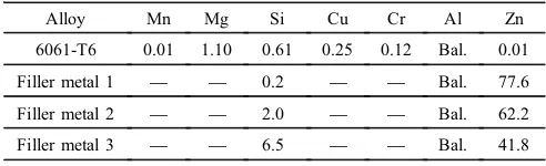
Alloy Mn Mg Si Cu Cr Al Zn 6061-T6 0.01 1.10 0.61 0.25 0.12 Bal. 0.01 Filler metal 1 ® ® 0.2 ® ® Bal. 77.6 Filler metal 2 ® ® 2.0 ® ® Bal. 62.2 Filler metal 3 ® ® 6.5 ® ® Bal. 41.8
were used in this experiment, the gas was controlled by the flow meter and the heating time was controlled by a automatic welding dolly.
The strength of brazed joints were tested on a SANS electromechanical universal testing system, and the average value of tested results were calculated and used. To ensure the accuracy of the results,five specimens were brazed at the same conditions with the same brazing alloy. The micro-structures of thefiller and joints were characterized by optical microscopy andfield-emission scanning electron microscope coupled to energy dispersion X-ray (EDX).
3. Results and Discussion
3.1 Characteristics of thefiller metals
Figure 1 shows the DTA curves of the filler metal 1 (Al 0.2Si78Zn),filler metal 2 (Al2Si62Zn), andfiller metal 3 (Al6.5Si42Zn). The peaks were all found at about 553 K in the three curves, from the AlZn equilibrium diagram (Fig. 2) the eutectoid reaction could be found at 550 K, and then the eutectoid ¡(Al)+©(Zn) formed. The solidus and liquidus changes followed the composition of thefiller metal. The operate window offiller metal 1 is about 90 K because the solidus of 6061 Al is about 855 K. The window is about
60 K when usingfiller metal 3, which is much larger than that of the typically Al12Sifiller metal (about 5 K). The brazing temperature too close to the melting point of the Al workpieces could increase the filler metal penetration into the base metal and cause erosion, results in distortion of the brazed part. The lower melting pointfiller metal is helpful to decrease this harmful phenomenon. Meanwhile, the melting point of the non-corrosive flux in this research is about 733 K, these three type of filler metal is very suitable for work with thisflux.
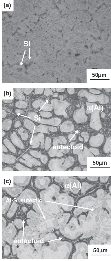
The microstructures of the filler metals could be seen in Fig. 3, when the compositions changes in thefiller metal, the microstructures changes obversely. The small silicon particles evenly dispersed in the Al0.2Si78Zn alloy, as shown in Fig. 3(a). However, needlelike primary silicon phases were found when the Si content is 2.0 mass%while the reticular Si phase formed when the Si content reaches 6.5 mass%. Si could react with Al to form AlSi eutectic, but seldom Si
Fig. 1 DTA curve of thefiller metals.
Fig. 2 AlZn equilibrium diagram.
Si
(a)
50μm
Al-Si eutectic
(c)
50μm
(Al)
eutectoid
α
Si
(b)
50μm
α
(Al)
eutectoid
[image:2.595.55.281.68.248.2] [image:2.595.328.521.71.521.2] [image:2.595.49.289.282.473.2]could resolve in Zn from ZnSi equilibrium diagram, meanwhile, ZnAlSi could not form the ternary compound. So the dark phase surround¡(Al) in Figs. 3(b) and 3(c) may be the eutectoid ¡(Al)+©(Zn). From the XRD pattern of filler metal 3 (Fig. 4), the ¡(Al), ©(Zn) and the Si phases could all be found, by the analyze above, the phases in the filler metal are¡(Al), eutectoid¡(Al)+©(Zn), AlSi eutectic as well as the Si particles.
3.2 Microstructure of the 6061 Al brazed joints
Figure 5 shows the microstructure of the 6061 Al brazing seams using filler metals 1, 2 and 3, sound joints could be obtained. The bamboo shoot-like solid solutions were formed at the interface of the joint, this type of solid solutions is helpful for improve the strength of the joints. The Si particles distributed finely in the brazing seam, and in the brazing seam offiller metal 3, both the primary silicon and the AlSi eutectic were found.
To understand the phase construction of the brazing seam by filler 2, the large magnification picture were obtained (Fig. 6). From the result list in Table 2, the content of Al in the brazing seam is much higher than the filler (36 mass%), show that Al dissolution from base metal into thefiller and formed these supersaurated solid solution phases. The white phase B in Fig. 6 consists of about 97 mass%Zn, Movahedi8)
thought it is a solid solution phase. But in Movahedi’s study, the pure zinc was used as thefiller metal, usingfiller 2, this zinc rich phase could also formed after brazing. Dong11)
reported that a cermet composite consisting of a ZnO network embedded in a ZnAl matrix when using ZnAl alloy weld the 5A02 Al to stain steel by gastungsten arc welding. The ZnO network structure were formed by the reaction of oxygen on the stainless steel surface and liquid zinc, and upon cooling, some ZnO arms grew upward into the weld and broke down into strips or islands. But in this study, no oxygen were found in the zinc rich phase, the flux used when brazing could remove the oxide on the Al surface and keep the wetting interface isolated from the oxygen in the air. By the results above and the AlZn equilibrium diagram, this white phase may be©(Zn) phase.
Movahedi et al.8) did not find the evidence of eutectoid
phase formation in the microstructures of the brazing seam, and the absence of eutectoid phases may be related to the nonequilibrium solidification during brazing. But from the
EDX result of area C in Fig. 6, we found this area with 65.97 mass%zinc and 34.03 mass%aluminum which is close to the eutectoid area. In as-cast ZA48 alloys, Yan et al.12)
found the eutectoid©(Zn)+¡(Al) surround with the primary
¡-dendrites structure, but they did not report the element distribution. By the content rate of zinc and aluminum, area C may be the eutectoid ©(Zn)+¡(Al) phase and it formed surround the ©(Zn) phase. Area D is¡(Al) from the result list in Table 2, the content of Al in the brazing seam is much higher than the filler (36 mass%), show that Al dissolution from base metal into the filler and formed these supersaturated solid solution phases. The diffusion of the aluminum and zinc to each other is helpful for the joint strength due to solid solution hardening.
Some micro-cracks were found on the Si particles, as showed in Fig. 7, and these micro-cracks may be the initiate crack of the joint when bear the force. Because of the difference of the thermal expansion coefficient between Si
Fig. 4 XRD pattern offiller metal 3.
(a)
100μm
Base metal
Brazing Seam
(c)
100μm
Base metal
Brazing Seam
Si
(b)
100μm
Base metal
Brazing Seam
Si
[image:3.595.54.281.64.230.2] [image:3.595.327.520.66.511.2]phase and the solid solutions, these micro-cracks may be formed by thermal shrinkage stress of the joint when cooling. The larger the Si phase, the easier cracks would form. From the XRD patterns of the brazing seam (Fig. 8), the brazing seams contained ©(Zn), ¡(Al) and Si phase. With the increasing of Al content in the filler metal, the diffraction peaks of©(Zn) decrease.
3.3 Tensile strength of the brazed joints
Figure 9 summarizes the tensile strength of the joints brazed by the threefiller metals. The results indicated that the strength of the brazed joints are much different regarding to thefiller metal. The 6061Al joint offiller 3 shows the highest value-129 MPa while the joints of filler 1 and 2 is 101 and 109 MPa, which means the higher content of Al in the brazing alloy are beneficial to increase the strength of the joints. From the strength of the joints we could also found that thought more silicon particles formed in the brazing seam offiller 3, the tensile strength did not decrease compare
to thefiller 1 joints. The higher Al content infiller metal, the higher strength of the 6061 Al brazed joint, this tendency is similar as the research result by Liu,13) as the Mg content
[image:4.595.100.497.68.210.2]in thefiller increased, the tensile-shear strength of the AZ31
Table 2 Composition and possible phase of the brazing seam.
Measure point Element (mass%) Possible phase Zn Al Si
A ® 3.39 96.61 Si
B 96.81 3.19 ® ©(Zn) C 65.97 34.03 ® ©(Zn)+¡(Al) D 33.20 66.80 ® ¡(Al)
(a)
15μm
(b)
3μm
Fig. 6 SEM observations of 6061 Al brazing joint usingfiller metal 2 ((a) interface, (b) brazing seam).
5μm
Fig. 7 Si particals in the brazing seam.
(a)
(b)
(c)
Fig. 8 XRD pattern of 6061 Al brazing seam ((a)filler 1, (b)filler 2, (c)
[image:4.595.314.533.248.699.2] [image:4.595.55.285.261.527.2]brazing joint increased from 30 MPa to more than 50 MPa. Meanwhile, the Zn and Al have a large solid solubility in each other, and Si could also solution in the ¡(Al) solid solutions, which could increase the joint strength by solid solution hardening.14)
3.4 Typical fracture of the brazed joints
Typical fracture morphologies of 6061 Al joints (joint 1, 2, 3) brazed byfiller metal 1, 2, 3 are shown in Fig. 10, they all showing the brittle fracture pattern. The fracture of the brazed joint exhibits intergranular fracture in joint 1 and 2, and micro cracks can be seen in the fracture. Some of the transgranular fracture could be found in joint 3, and the Si particles may fall off the fracture when tensile from Fig. 10(c). These Si particles in the brazing seam is similar like the intermetallic brittle compounds, which could deteriorate the tensile property of the joint.15,16) The phase
could be optimized by control the cooling rate17) and the
alloying method.18)Because of the Al content infiller metal 3
is much higher thanfiller 1 and 2, more¡(Al) formed in the brazing joint 3, the ¡(Al) greatly increased the tensile strength of the 6061Al brazing joint.
4. Summary and Conclusion
The research developed a series of economic and available AlSiZnfiller metals to join 6061 aluminum, the following conclusions could be obtained:
(1) The AlSiZn seriesfiller metals with a liquidus around 500°C could successfully used for braze the 6061 Al. The small primary silicon particles could be found in Al0.2Si78Znfiller metal while the needlelike primary silicon particles could be found in thefiller metal while the Si content is 2.0%. Meanwhile, the AlSi eutectic could be found in the Al6.5Si42Znfiller metal. (2) The eutectoid¡(Al)+©(Zn),¡(Al),©(Zn) as well as the
Si particles could also be found in the brazing seam. The AlSi eutectic could be found when using Al 6.5Si42Zn filler metal. Some micro-cracks formed in the Si particles could be the crack source of the brazed joint.
(3) The tensile strength of the Al6.5Si42Zn brazed joints could achieve 129 MPa. The fracture morphologies of the joints exhibits intergranular fracture while some transgranular fracture could be found in Al6.5Si42Zn joint.
Acknowledgements
The project is supported by the Foundation of Scientist and Technician Serve the Enterprise, The Ministry of Science and Technology, China (Project No. 2009GJC20040).
REFERENCES
1) W. S. Miller, L. Zhuang and J. Botema:Mater. Sci. Eng. A280(2000) 3749.
2) O. Engler and J. Hirsch:Mater. Sci. Eng. A336(2002) 249262.
3) L. C. Tsao, T. C. Tsai, C. S. Wu and H. T. Chuang:J. Mater. Eng. Perform.10(2001) 705709.
4) S. Y. Chang, L. C. Tsao, T. Y. Li and H. T. Chuang:J. Alloy. Compd.
488(2009) 174180.
5) M. Ding, P. L. Zhang, Z. Y. Zhang and S. Yao:Ultrason. Sonochem.17
(2010) 292297.
6) T. Nagaoka, Y. Morisada, M. Fukusumi and T. Takemoto: J. Mater. Process. Tech.209(2009) 50545059.
Fig. 9 Tensile strength of the 6061 Al brazed joints.
Crack
(b)
Cracks
(a)
Si
(c)
[image:5.595.76.261.67.204.2]20μm
[image:5.595.323.527.70.506.2]Sci. Technol.65(2005) 19591963.
8) M. Movahedi, A. H. Kokabi and H. R. Madaah Hosseini: Mater. Charact.60(2009) 441446.
9) L. C. Tsao, M. J. Chiang, W. H. Lin, M. D. Cheng and T. H. Chuang:
Mater. Charact.48(2002) 341346.
10) K. Suzuki, M. Kagayama and Y. Takeuchi:Light Metal43(1993) 533 538.
11) H. Dong, L. Yang, C. Dong and S. Kou:Mater. Sci. Eng. A527(2010) 71517154.
(2009) 41694173.
13) L. M. Liu and Z. H. Wu:Mater. Charact.61(2010) 1318.
14) L. Ma, D. Y. He, X. Y. Li and J. M. Jiang:Mater. Lett.64(2010) 596 598.
15) M. Ghosh and S. Chatterjee:Mater. Charact.54(2005) 327337.
16) P. He and D. Liu:Mater. Sci. Eng. A437(2006) 430435.
17) M. A. Mofid, A. Abdollah-zadeh and F. M. Ghaini:Mater. Design36
(2012) 161167.