Effects of residual charge on the performance of
electro-adhesive grippers
SINGH, Jatinder, BINGHAM, Paul <http://orcid.org/0000-0001-6017-0798>,
PENDERS, Jacques <http://orcid.org/0000-0002-6049-508X> and MANBY,
David
Available from Sheffield Hallam University Research Archive (SHURA) at:
http://shura.shu.ac.uk/13371/
This document is the author deposited version. You are advised to consult the
publisher's version if you wish to cite from it.
Published version
SINGH, Jatinder, BINGHAM, Paul, PENDERS, Jacques and MANBY, David (2016).
Effects of residual charge on the performance of electro-adhesive grippers. In:
ALBOUL, Lyuba, DAMIAN, Dana and AITKENS, Jonathan M., (eds.) Towards
autonomous robotic systems. TAROS 2016, Sheffield, UK, June 26--July 1, 2016,
Proceedings. Lecture Notes in Computer Science. Lecture Notes in Artificial
Intelligence (9716). Springer International Publishing, 327-338.
Copyright and re-use policy
See
http://shura.shu.ac.uk/information.html
adfa, p. 1, 2011.
© Springer-Verlag Berlin Heidelberg 2011
Study of effect of residual charge on the performance of
Electro-adhesive gripping solution, when used in
automation of pick and place of insulating materials
Jatinder Singh
1,2, Paul Bingham
1, Jacques Penders
1,2,David Manby
31Materials and Engineering Research Institute, Sheffield Hallam University, UK 2Sheffield Robotics, UK
3Aylesbury Automation Ltd, Aylesbury, UK
Abstract. Electro-adhesion is the new technology for constructing gripping so-lutions that can be used for automation of pick and place of a variety of mate-rials. Since the technology works on the principle of parallel plate capacitors, there is an inherent ability to store charge when high voltage is applied. This causes an increased release time of the substrate. This paper addresses the is-sue of residual charge and suggests ways to overcome the same, so that the performance of the gripper can be improved in a cycle of pick and release. Also a universal equation has been devised, that can be used to calculate the per-formance of any gripping solution. This equation has been used to define a de-sired outcome (K) that has been evaluated for different configurations of the suggested eletro-adhesive gripper.
Keywords: Advanced Technology, Robot Grippers, Dielectric materials, Auto-mation
1
Introduction
Although force calculations have been the primary basis for analysis of perfor-mance of an EAG, yet there are many other key parameters that need to be considered for the same. Since EAG works as a parallel plate capacitor, the amount of storage of charge becomes one such key component, which needs to be taken into account while working with an EAG.
This paper presents a simplistic equation that can be used as a tool for analysis of desired outcome, thereby reflecting the performance of any gripping solution. Using this equation, experimental results can be evaluated and analyzed for a complete cycle of pickup and release of various substrates. Experiments have been performed to sup-port the theory of EAG working as a parallel plate capacitor, thereby storing charge and recommendations have been made to optimize this solution of using EAG as an improved gripping solution for insulating material. The key focus is on the use of dielectric in the configuration of EAG that causes the storage of charge, thereby im-pacting the performance of gripping solution. There recommendations can be useful for further development and deployment of EAG in an industrial environment to achieve desired results.
2
Background
Grippers are divided into mainly four types depending upon the application they are deployed. Ranging from microspines to vacuum suction techniques, each gripper technology has its own advantages and disadvantages. For application of automating material pick up usually astrictive grippers are preferred. As the name suggests astric-tive grippers use some kind of binding force for adhesion. Key techniques in this cat-egory of grippers include vacuum suction, electro-adhesion and Van Der Waals forces based gripper. With capability of electrostatic attraction known from ancient Greeks times and the ability to attract small particles after charging an ebony rod known to every school child having an interest in science [4], research on electro-adhesion has led the technique to be used in different industries for applications including grippers [5, 6], electrostatic chucks [7-9], cloth manufacturing robotics [10] and, recently, wall climbing robots [11, 12, 14].
Even though electro-adhesion is proven to be at a relatively advanced stage of practical development and researchers have explored some of its capabilities, yet analysis on key component of EAG on a production level scale has been missing from the literature till date.
3
Theory
[image:4.595.198.407.302.435.2]3.1
Principle of an Electro-Adhesive Gripper
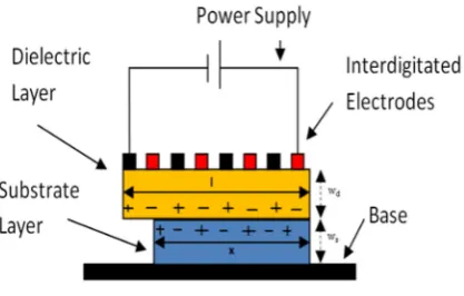
Fig. 1. Principles of Electroadhesion
1.Electrodes: Conductive metal that acts as the plates of the parallel plate capacitor. These are provided with high voltage so as to charge the EAG.
2.Dielectric: Insulating layer attached to the electrodes that allows for storage of charge between the plates.
3.Substrate: Object to be picked up by the EAG.
4.Base material: Material on which the substrate is placed. 5. Power Supply: High voltage supply used to charge the EAG
place due to polarization of the substrate in the presence of the electric field generated between the electrodes as a result of storage of charge.
The principle of EAG has been best described as a parallel place capacitor in many research papers [3, 2, 18]. In [3], the concept is explained in terms of a single pole gripper, in which electrode plate forms one plate and the base material forms the sec-ond plate of the parallel plate capacitor. The dielectric material and the substrate to-gether form the insulating material between the parallel plates of the capacitor. Thus the whole system forms a method of charge storage. In [3], it has been demonstrated that the net charge accumulation is directly proportional to the dielectric strength of the dielectric material used as well as the substrate. Mathematical modelling of dy-namic properties (pick up and release time) has been shown for actual calculation which proves that the pickup and release times are directly proportional to the total number of charges developed.
The performance of an EAG is measured by doing force calculations based on par-allel plate capacitance. A standard equation to calculate force is [18,15]
𝑓 =
(1)
Where f is the force between the two plates (N),
𝜀
is the relative permittivity of the dielectric,𝜀
is the relative permittivity of the vacuum, V is the voltage applied to the plate's measure in Volts (V) and d is the distance between the plates (mm).As f is directly proportional to the dielectric constant therefore higher the dielectric constant more is the force generated by the EAG. This would suggest that an EAG with high dielectric constant is more efficient for picking heavier loads. Using a high dielectric constant causes more charge to build up in the electrodes as capacitance is increased [18] and that may result in the increase in release time [17], when the volt-age is shut off (as will be seen later in experiments). Therefore this forms a trade off in the design of an EAG. The experimental work done in this report has been concen-trated on the importance of dielectric layer in an EAG and experiments have been devised accordingly.
3.2
Safety measures
3.3
Parameter (K) that defines an effective gripping solution.
For successful pick up and release of polymeric material such as gloves on a pro-duction line running 24 hours a day, repeatable and reliable (R2) gripping results are required.
R2 can be defined as achieving consistent results (that is desired outcome is achieved) for every cycle of pick up and release. Thus the R2 needs to be analyzed in terms of efficiency of the gripping solution. A measure to calculate efficiency is needed to judge the effectiveness of the gripper on a production line scale. Therefore we define efficiency as the ratio of number of successful pick up and release cy-cles/trials to the total number of cycy-cles/trials performed. Higher the efficiency (ŋ), higher is the ability to achieve R2 results.
ŋ = 𝑛𝑜. 𝑜𝑓 𝑡𝑟𝑖𝑎𝑙𝑠 𝑤𝑖𝑡ℎ 𝑑𝑒𝑠𝑖𝑟𝑒𝑑 𝑜𝑢𝑡𝑐𝑜𝑚𝑒
𝑡𝑜𝑡𝑎𝑙 𝑛𝑢𝑚𝑏𝑒𝑟 𝑜𝑓 𝑡𝑟𝑖𝑎𝑙𝑠 ∗ 100 (2)
This is a universal equation that can be used to analyze not only electro-adhesive griping solution but any gripping solution. Thus to analyze ŋ, first we need to define what is a desired outcome (successful pick and release). Since we are focusing on analyzing an effective gripping solution for pick and release cycle, in order to achieve R2, a successful outcome depends on the following relationship:
Desired outcome 𝛼 ∗
( )∗( ) (3)
Thus we define parameter for desired outcome
𝐾 =
××
(4)
Where, P = {0,1} 0 = Substrate not picked up 1 = Substrate picked up R = {0,1} 0 = Substrate not released
1 = Substrate released TP = Time to pickup
TR = Time to release
(Units for desired outcome: sec-2 )
By setting desired values of above variables, the desired outcome (K) can be de-fined and thereby analysis on efficiency can be performed. Thus this equation can be used to analyze and compare experiments involved in this application for not only electro-adhesive grippers but for any gripping solution.
to measurement constrains and inefficiencies). In this paper, equation (4) has been used to analyze the output of the EAG in two configurations; with dielectric and without dielectric layer. Further work will be done to calculate the overall efficiency by performing repeated experiments. This will therefore help in achieving a gripping solution with optimum R2 results.
4
Experimental Setup
The aim of the experiments is to show the impact of the dielectric layer on the per-formance of an EAG in completing one cycle of pick up and release of a substrate. For this purpose, we have chosen four different substrates. (i) High density polyeth-ylene (HDPE) (ii) Polycarbonate (iii) Mobile phone screen glass (iv) Nitrile Glove. The selection of these substrates was based on the fact that electro-adhesion has dif-ferent impact on difdif-ferent materials due to materials having difdif-ferent molecular struc-ture, and different electrical properties.
Two different configurations of gripper were developed. The electrode structure in both was inter-digitated structure, as inter-digitated structure has been the most effec-tive of all the structure [13]. Two configurations prepared are as follows
1. Bare Electrodes: B Electrodes as further defined in the study
[image:7.595.127.474.378.534.2]2. Bare Electrodes and Polyimide (as dielectric): D electrodes as further de-fined in the study
Fig. 2. Two configurations of grippers
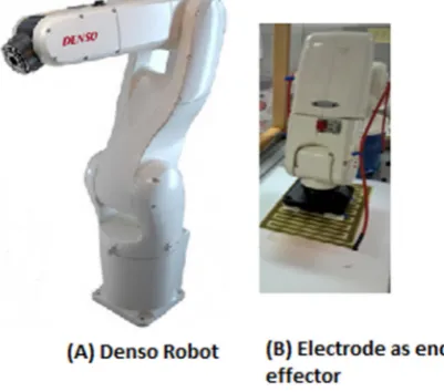
The experiments were performed using a VP series Denso robot fig. 3 to replicate the environment of a production line. The constructed electrode was placed as an End effector fig. 3 on the Denso arm.
Fig. 3. VP Series DENSO robotic arm
A cycle for the experiment is defined as the pick-up and release of the substrate by the robot arm. The substrate is placed in a known location on the base. These coordi-nates are fed into the Denso arm. As shown in Figure 4, the arm begins the cycle from a known position A to the position B of the substrate on the base. It then attempts to pick up the substrate by pressing the end effector on the substrate. The next step is for the arm to travel to a known position C. After this, the voltage is cut off and the time to release the substrate is noted down.
The experiments were performed for each substrate and electrode combination and results for the desired outcome were noted down (as per equation (4)). The parameters for desired outcome for our experiments are defined as:
P = 1 (substrate should be picked up) R = 1 (substrate should be released) TP = 1 sec (Pick up must be instantaneous)
TR = 1 sec (Release must be instantaneous when voltage is shut off)
Fig. 4. Robotic arm positions during the experiment
5
Results
[image:9.595.127.436.448.664.2]5.1
D Electrodes
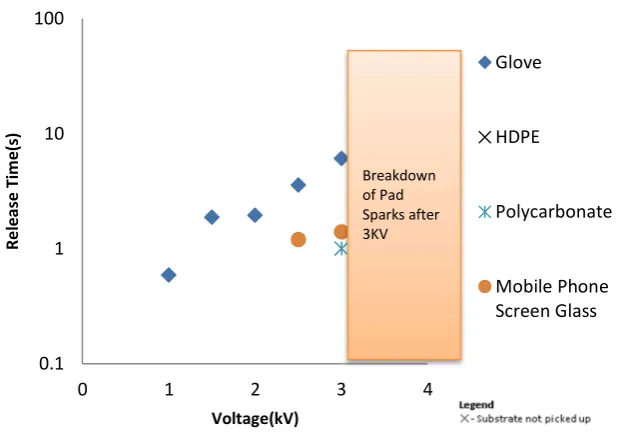
Fig. 5. Release time results of D electrodes 0.1
1 10 100
0 1 2 3 4
Re
le
as
e
Ti
m
e(
s)
Voltage(kV)
Glove
HDPE
Polycarbonate
Mobile Phone Screen Glass
The results for D electrodes show that the EAG is unable to pick up HDPE. For glass and polycarbonate, adhesion was possible only above 2500 V and 3000 V re-spectively, whereas the glove has been picked up at 1000V. It was also observed that the release time for the glove increased considerably at high voltage. The D electrode started to arc at 3kV restricting any further testing on this particular pad as arcing can lead to substantial damage to the properties of the substrate and the EAG, thereby providing misleading results to the experiment.
[image:10.595.137.456.270.528.2]5.2
B Electrodes
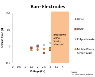
Fig. 6. Release time results for B electrodes
When compared to the D electrodes, the results for B electrodes show that the pick-up voltage for gloves was increased to 2000V, for glass it was 1000V and for polycarbonate it was 1500V. The B electrodes were also able to pick up HDPE at 1000V. Also all the substrates demonstrated instantaneous releases. Also with in-crease in voltage, the release time for glove was not inin-creased.
0.1 1 10 100
0 0.5 1 1.5 2 2.5 3 3.5 4
Re
le
as
e
Ti
m
e
(s
)
Voltage (kV)
Bare Electrodes
Glove
HDPE
Polycarbonate
Mobile Phone Screen Glass Breakdown
Overall table for desired outcome (as calculated based on equation 4) is shown be-low:
Table 1. Desired outcome measurements for both gripper configurations (D and B electrodes) (Units for desired outcome: sec-2)
Mobile
Phone
Screen Glass
Nitrile
HDPE
Polycarbonate
Voltage (V)
D
B
D
B
D
B
D
B
500
0
0
0
0
0
0
0
0
1000
0
1
1
0
0
0
0
0
1500
0
1
0.5
0
0
1
0
0
2000
0
1
0.5
1
0
1
0
1
2500
.83
1
0.2
1
0
1
0
1
3000
.71
1
0.125 1
0
1
1
1
Number of trials desired outcome
achieved
0
5
1
3
0
4
1
3
6
Analysis of Results
The above experiments show promising results for the B electrodes. All the sub-strates were released instantaneously and the pick-up voltages were also reduced (with nitrile glove as exception). HDPE was of particular interest, since it was not picked at all by the D electrode whereas the B electrode was successfully able to pick and release it. This proves that even though there is storage of charge, enough force is not generated to pick HDPE, therefore force calculations alone cannot be used to determine the performance of an EAG.
Since the desired outcomes were better for B electrodes, it supports our theory of storage of charge causing an increase in the release time of an EAG. Therefore for applications where quick Tp and Tr are required, B electrodes are more suitable whereas for applications where it is necessary to hold the substrate for longer dura-tion, D electrodes are to be used.
7
Conclusion
We conclude that traditional method of mere force calculations are not enough for evaluating the performance of an EAG. There are various other parameters that must be taken into account. One such parameter is the storage of charge in the substrate and dielectric, which plays a vital role in achieving the desired outcome. To evaluate the effect of storage of charge on the EAG, two configurations of electrodes were built; electrodes with polyimide as dielectric (D electrodes) and bare electrodes, with no dielectric attached (B electrodes).
Through experimentation and evaluation of results using the equation devised to check desired outcome, we concluded that the B electrodes provided more desired results, as they had a smaller pick up and release time, when compared to the D elec-trodes. This supports the theory of EAG working as a parallel plate capacitor. Since D electrodes contain the dielectric layer, they are able to store charge even after the voltage supply is shut off. Since the charge is not able to dissipate through the dielec-tric, it leads to a longer release time. Also this residual charge increases with increase in voltage that is applied to the EAG. The B electrodes on the other hand, do not have any charge storage mechanism and therefore release time for them is significantly less. (Instant release time = 1 seconds). In theory, there should be no release time delays with B electrodes since they only contain conductors, but practically some release time is seen as air between the substrate and the electrode also acts as a dielec-tric.
We also conclude that B electrodes can only be used to pick up substrates that are insulators since conductive substrates will create a short circuit on the electrodes, thereby causing large current to flow through them and destroying them. Therefore for applications that require quick pick up and release cycle for insulating materials, bare electrodes must be used in the construction of an EAG.
References
1. Y. Shimon, “Advances in Robotics and Automation: Historical Perspectives,” in Springer Handbook of Automation, 2009
2. G J. Monkman, Stefan Hesse Ralf Steinmann, Henrik Schunk, “Introduction to Prehension technology,” in Robot Grippered. Wiley,2007
3. Zhengwen Zhang, “Modeling and Analysis of Electrostatic Force for Robot Handling of Fabric Materials” in IEEE Transactions on Mechatronics, 1999, Vol.4,No.1
4. Trevena. D.H. - Static Fields in Electricity and Magnetism – Butterworths, London, 1961.
5. G. Monkman, “Electroadhesive microgrippers,” Industrial Robot: An International Journal, vol. 30, no. 4, pp. 326-330, 2003.
6. G. J. Monkman, “Robot Grippers for Use With Fibrous Materials,” The International Jour-nal of Robotics Research, vol. 14, no. 2, pp. 144-151, Apr. 1995.
7. G. I. Shim and H. Sugai, “Dechuck Operation of Coulomb Type and Johnsen-Rahbek Type of Electrostatic Chuck Used in Plasma Processing,” Plasma and Fusion Research, vol. 3, pp. 051-051, 2008.
9. J. Yoo, J.-seok Choi, S.-joon Hong, T.-hyun Kim, and S. J. Lee, “Finite Element Analysis of the Attractive Force on a Coulomb Type Electrostatic Chuck,” in International Conference on Electrical Machines and Systems, 2007, pp. 1371-1375.
10. G. J. Monkman, P. M. Taylor, and G. J. Farnworth, “Principles of electroadhesion in cloth-ing robotics,” International Journal of Clothing Science and Technology, vol. 1, no. 3, pp. 14-20, 1989.
11. H. Prahlad, R. Pelrine, S. Stanford, J. Marlow, and R. Kornbluh, “Electroadhesive Robots - Wall Climbing Robots Enabled by a Novel, Robust, and Electrically Controllable Adhesion Technology,” in IEEE International Conference on Robotics and Automation, 2008, pp. 3028-3033.
12. A. Yamamoto, T. Nakashima, and T. Higuchi, “Wall climbing mechanisms using electro-static attraction generated by flexible electrodes,” in International Symposium on Micro-NanoMechatronics and Human Science, 2007, pp.389-394
13. Juan P. Diaz Tellez, Jeff Krahn, and Carlo Menon, “Characterization of Electro-adhesives for Robotic Applications,” in IEEE international conference on Robotics and Biomimetics (ROBIO), 2011
14. Rong Liu, Rui Chen, Hua Shen and Rong Zhang, “ Wall Climbing Robot using Electrostatic Force generated by Flexible Interdigital Electrodes,” in International Conference on Robot-ics and BiomimetRobot-ics (ROBIO), 2011, pp.2031 - 2036
15. Jong Up Jeon, Toshiro Higuchi, “ Electrostatic Suspension of Dielectrics,” in IEEE transac-tions on Industrial Electronics, 1998, pp. 938 - 946
16. DuPoint, “Kapton Polyimide Film,” H-38479 datasheet, 2014
17. Electrogrip (March, 2013). Principles of Electrostatic Chucks. Electrogrip. Pittsburgh, USA [online]. Available: http://electrogrip.com/Egrip2013Support/Principles1no3.pdf