objects and application to tracking in microscope images.
BOISSENIN, Manuel.
Available from Sheffield Hallam University Research Archive (SHURA) at:
http://shura.shu.ac.uk/19364/
This document is the author deposited version. You are advised to consult the
publisher's version if you wish to cite from it.
Published version
BOISSENIN, Manuel. (2009). Template reduction of feature point models for rigid
objects and application to tracking in microscope images. Doctoral, Sheffield Hallam
University (United Kingdom)..
Copyright and re-use policy
See
http://shura.shu.ac.uk/information.html
Sheffield Hallam University Research Archive
1 0 1 923 07 5 4
Cilem University and IT Services ntre City Campus Sheffield SI i WB
All rights reserved
INFORMATION TO ALL USERS
The quality of this reproduction is dependent upon the quality of the copy submitted.
In the unlikely event that the author did not send a com plete manuscript and there are missing pages, these will be noted. Also, if material had to be removed,
a note will indicate the deletion.
uest
ProQuest 10694245
Published by ProQuest LLC(2017). Copyright of the Dissertation is held by the Author.
All rights reserved.
This work is protected against unauthorized copying under Title 17, United States C ode Microform Edition © ProQuest LLC.
ProQuest LLC.
789 East Eisenhower Parkway P.O. Box 1346
Template Reduction of Feature
Point Models for Rigid Objects
and Application to Tracking in
Microscope Images
Manuel Boissenin
A thesis subm itted in partial fulfilment of the requirements of Sheffield Hallam University
for the degree of Doctor of Philosophy
Microsystems and Machine Vision Laboratory
The undersigned hereby certify th at they have read and recommend to the Faculty of Arts, Computing, Engineering and Sciences for acceptance a thesis entitled “T e m p la te R e d u c tio n of F e a tu re P o in t M o d els for R ig id O b je c ts a n d A p p lic a tio n to T rack in g in M icro sco p e Im ag es” by M an u el B o issen in in partial fulfillment of the requirements for the degree of D o c to r o f P h ilo so p h y .
Dated: February 2009
Research Supervisor: ______________________ :_________ Dr Balasundram Amavasai
Examining Com m ittee:_____________________ ;______ __ Professor Huosheng Hu
Professor Melvyn Smith
Date: F e b ru a ry 2009
Author: M an u el B o issen in
Title: T e m p la te R e d u c tio n of F e a tu re P o in t M o d els fo r R ig id O b je c ts a n d A p p lic atio n to T rack in g in M icro sco p e Im ag es
Department: M icro sy stem s a n d M ach in e V ision L a b o ra to ry Degree: P h .D . Convocation: F e b ru a ry Year: 2008
Permission is herewith granted to Sheffield Hallam University to circulate and to have copied for non-commercial purposes, at its discretion, the above title upon the request of individuals or institutions.
THE AUTHOR ATTESTS THAT PERMISSION HAS BEEN OBTAINED FOR THE USE OF ANY COPYRIGHTED MATERIAL APPEARING IN THIS THESIS (OTHER THAN BRIEF EXCERPTS REQUIRING ONLY PROPER ACKNOWLEDGEMENT IN SCHOLARLY WRITING) AND THAT ALL SUCH USE IS CLEARLY ACKNOWLEDGED.
Signature of Author
Contents
List of Figures
x
List of publications
xx
Abstract
xxii
1 Introduction
2
1.1 Rationale and m otivation... 2
1.1.1 The MINIMAN p ro je c t... 3
1.1.2 The MiCRoN p ro je c t... 3
1.2 Research aims and objectives . . . ... 4
1.2.1 Choices and d iscu ssio n . . 5
1.3 Research methodologies . . ... 10
1.4 C o n trib u tio n s . ... 10
1.5 Organisation of the thesis ... 11
2 Literature review
13
2.1 In tro d u ctio n ... 132.2 Connected techniques to visual tracking... 15
2.2.1 Detection and initialisation ... 15
2.2.2 Background subtraction and movement detection . . . 16
2.2.3 M athematical M orphology... 16
2.2.4 Techniques to match point s e t s . . . 17.
2.2.5 Image distortion ... 21
2.3 Visual t r a c k in g ... 23
2.3.1 Kalman filter based visual tr a c k in g ... . 25
2.3.2 Particle filter based visual tr a c k in g ... 27
2.4 The Hough transform ... 32
. 2.4.1 In tro d u ctio n ... 32
2.4.2 Hough transform and tracking ... 33
2.4.3 The randomised Hough transform ...34
2.5 Summary . ... 37
3 Particle filters
38
3.1 In tro d u ctio n ... . 383.2 A real world ex am p le... 39
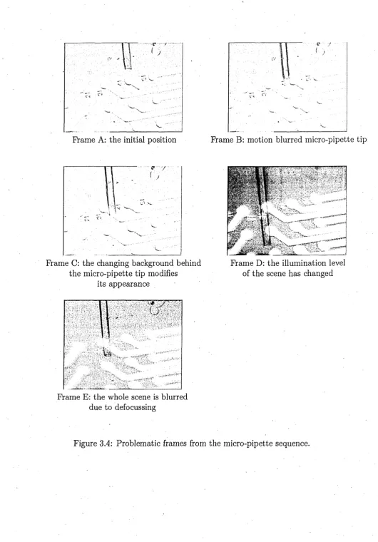
3.3 Typical encountered is s u e s ... 40
3.4 Preliminary approaches to solve these issues ...41
3.4.1 Dynamic tem plate u p d a tin g ... 43
3.4.2 Taking measures . . ... 44
3.4.3 Improving the matching paradigm . . ... 46
3.4.4 Geometric Branch-and-Bound M a tc h in g ... 48
3.5 Clustering particles . ; ... . 50
3.5.1 Locating the statistical modes . . . . ... . 50
3.5.2 M ethod form alisation... 51
3.5.3 An 0 (n ) algorithm to cluster p a r tic le s ... 51
3.5.4 Location of the micro-pipette using further measurements of the im a g e ... 54
3.6 Further improvements . . . ... 56
3.6.1 Overcoming the effect of c lu tte r ... 56
3.6.2 Integrating the kinematics of the o b je c t. ... 56
3.6.3 Partial re-in itialisatio n ...57
3.6.4 Modes filtering . . ... 58
3.7 A generic particle filter a rch itectu re... . 59
3.7.1 Description of the architecture ...59
3.7.2 Issues related to the initialisation of the class ...59
3.7.3 Conception ... 60
3.7.4 Extensions ... 62
3.8 S u m m a r y ... . 63
3.8.1 Possible improvements . ... 64
4.1 In tro d u ctio n ... 65
4.1.1 Square example . . ...65
4.1.2 Circle example ... 69
4.1.3 Locating a shape on an im a g e ... 71
4.2 Self similar set of p o i n t s ... 75
4.3 Robustness to n o ise ... 78
4.4 Template reduction, a simple exam ple...79
4.5 Evaluation of the characterising value of a set of p o i n t s ... 79
4.6 A generic algorithm for the pose estimation of rigid o b je c ts ... 82
4.7 Summary ■ . . 84
4.7.1 Future research . . . ... 85
5 The stencil estimator
86
5.1 In tro d u ctio n ... 865.2 The stencil e stim a to r... 86
5.3 Robustness ... 91
5.4 Implementation of the tracking algo rith m ... 92
5.5 Stencil r e d u c tio n ... 96
5.6 Summary . . ... 98
6 Experiments
100
6.1 Tracking of Microscopic Objects ... 1006.1.1 Context and experimental setting . ... 100
.6.1.2 Algorithm . ... ... . 103
6.1.3 Complexity analysis ... 105
6.1.4 Parallelisation...110
6.1.5 S u m m a r y ... I l l 6.2 Testing of the stencilled Hough transform using synthetic data . . . .1 1 2 6.2.1 Experiments and r e s u l t s ...112
6.2.2 Comparison with different similarity methods using an ex- ■ haustive search ...•. 132
6.2.3 Summary ... 142
6.3 Testing the particle filter on the micro-pipette tracking sequence . . . 143 6.4 Testing the stencil Hough transform on the pipette video sequence . .151
6.4.2 The motion model . ... 153
6.4.3 S u m m a r y ... 156
7 Conclusion
159
7.1 Contributions : ... 1597.2 Future re s e a rc h ... 160
A Fitting a square to a set of points
162
A .l 3 points c ase ... 162A.2 4 points case ... ' ...163
A,3 5 points . ... 167
A.4 Perspective transformation . ...169
B Dense disparity map using epipolar geometry
171
B .l Depth maps of 3-D s c e n e s ... , ... 171B.1.1 Stereo vision... . 171
B .l.2 Camera c a lib ra tio n ... 172
B .l.3 Stereo calib ratio n ... 175
B.1.4 Correspondence problem ...175
B .l.5 D iscussion... 177
B .l.6 S u m m a r y ... 178
B.2 Model building alternatives ...179
B.3 Im p lem en tatio n ...180
B.4 T ria n g u la tio n ... 181
B.5 Summary ... 183
C Further testing of the particle filter
184
C .l Table tennis sequence ... 184C.2 Rubik’s cube s e q u e n c e ... 184
D Machine vision and computer vision
191
E Tracking source code
193
F Extended abstract
200
List of Figures
1.1 An artist impression of the MiCRoN project made for the project pro posal: mini robots, 1 cm across,- working cooperatively in an assembly
task ... 4
1.2 Overview-of the MiCRoN set up during the integration stage. The camera is mounted on a Miniman robot. In the front, an infrared communication device is mounted on a USB p o r t . . 4 1.3 A tethered MiCRoN robot with its gripper under, the microscope cam
era. ... 5 1.4 The set up at Sheffield Hallam university, the camera support is
mounted on a piezo-electric three degree of freedom translation stage. Green LEDs are used to illuminate the scene. Green has been cho sen to avoid interferences with the infrared communication of the MiCRoN robots. 1 pixel in the obtained image corresponds to 1 mi
crometre (fi m )... 6
1.5 The graphical user interface of the recognition and tracking soft ware. The x-y axis frame indicates the position of the recognised and tracked syringe chip. The image has been taken with a optical microscope and its quality is better than the images obtained with the MiCRoN camera... 7 1.6 The MiCRoN robot... . 7
2.1 By obtaining the intrinsic parameter it is possible to determine where each point expressed in the camera frame will be projected onto the
image. ... 22
2.2 A red parallelepiped and a white line projected on the image using the image formation m o d e l... 24
supply edge highlighted in previous figure appears straight... 24 2.4 The Kalman filter can be divided into 2 s ta g e s ... 25 2.5 Diagram to explain the Hough transform, see text for explanation. . . 33
3.1 Particle filtering stages... 39
3.2 The original pen tip tracking algorithm using particle filters [lj. . . . 40 3.3 The tracking of the pipette tip has failed. The white square is the
tracked location (at the top centre position of the image). Top left hand corner is the tem plate image. ... 41 3.4 Problematic frames from the micra-pipette sequence... 42 3.5 Tracking with the tem plate updating mechanism ru n n in g ...43 3.6 Image showing the value of the correlation measure within a region
of interest. The positions with high correlation values are coloured following the colour code described in page 44...45 3.7 Frames showing the tracking results using edge tem plate matching.
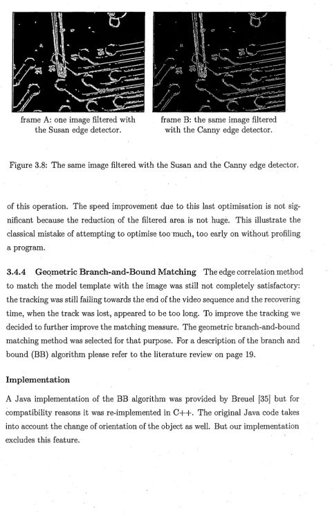
The top left corner of images shows the edge tem plate of the micro pipette tip. . ... 47 3.8 The same image filtered with the Susan and the Canny edge detector. 48 3.9 Frames showing the results of edge correlation with only part of the
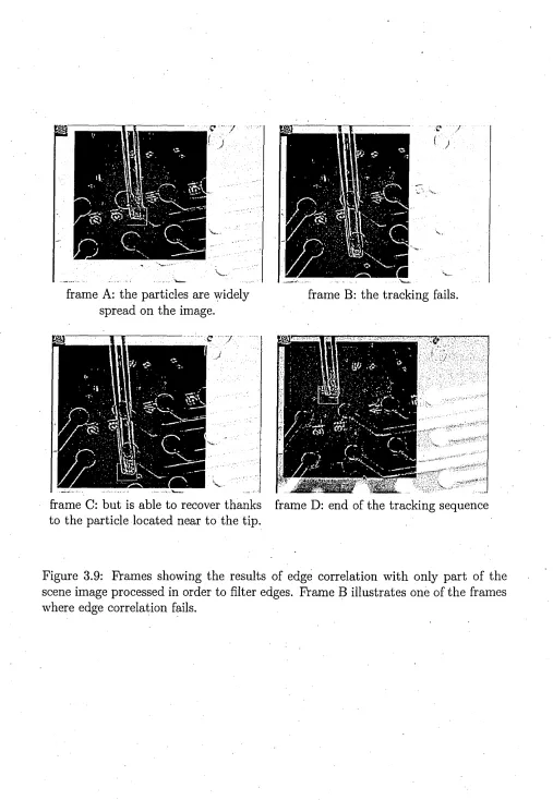
scene image processed in order to filter edges. Frame B illustrates one of the frames where edge correlation fails... 49 3.10 In frame A points represents particles. Frame B shows the thresholded
particles. In frame C, the boundaries show how these particles are grouped and can be seen as the set bounds . Frame D shows how the other particles are collated into the corresponding sets. Frame E shows the resulting peak points, compared with frame B the modes are shifted from the thresholded particles and the 2 closed thresholded particles have been integrated in the same mode...52 3.11 Tracking of the micro-pipette tip. Modes give an indication of the
location of the peaks of the pdf sampled by the particles... .... 55
3.12 Tracking stages...■ 58
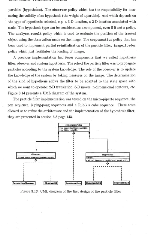
3.13 UML diagram of the first design of the particle filter ... 61 3.14 UML diagram of the final implementation of the particle filter . . . . 62
4.2 The three squares, modulo rotations, having these two points as corners. 67 4.3 Two possible configurations of 3 points and example of squares that
matches these configurations. On the left, 2 points are closer whereas on the right, points are equidistant... 67 4.4 The points a,b,c and d uniquely define a square...68 4.5 An impossible configuration and 2 possible configurations of 4 points
that fit more than one square. . . ...69 4.6 A configuration of 5 points that can be fitted by only one square. . . 70 4.7 A tem plate (S), its associated state space (T) and the corresponding
look-up table (L). Colours are used to represent the states referenced
by the look-up table... 80
4.8 Figures A-D show non ambiguous reduced templates. Figures E,F
show ambiguous reduced te m p la te s ...80
5.1 The stencils of the “star” shape corresponding to the coloured area of the transformation space have been drawn in the image space. The coloured regions are the set of points overlapped by the shape when it is moved according to the transformations of the subset having the same colour in the transformation space... 87 5.2 Pre-processing stage ...93 5.3 Tracking stage ... 95
6.1 Images from the gripper tracking sequence. The grippers in the left and right images are at different depths...101 6.2 Diagram of the set-up used for the experiments. A photo of the set-up
can be found figure 1.4, page 6. ...101 6.3 A subset of the stack of images th at serves as the gripper model . . . 102 6.4 A sample of some of the stencils p ro d u c e d ... 105 6.5 Key for figure 6.6 ... 107 6.6 Tracking using 4 sets of parameters, see figure 6.5 for keys and figure
6.1.3 for the corresponding tracking b e h a v io u r... 108 6.7 Speed comparison of the tracking of the gripper using different pa
6.10 Comparison of Qt threads and boost threads, both implementation uses Qt m utexes... 110 6.11 Comparison of the parallelisation on 2 processors using different im
plementations ... ... . . . ... . I l l 6.12 Speed comparison, one thread versus two t h r e a d s ... 112 6.13 Templates of the tracked shapes... 114 6.14 Appearance of the first image of the hand shape tracking sequence
for different noise levels. In percentage of image noise: 0, 4, 10, 16, 22, 28, 34, 40, 46 and 50% re sp ec tiv e ly ... 115 6.15 Appearance of the first image of the watch tracking sequence for dif
ferent noise levels. In percentage of image noise: 0, 4, 10, 14, 20, 26, 30, 34, 38, 42, 46 and 50% respectively ... 116 6.16 The z-axis corresponds to the number of images where the tracking
result differs from the ground truth. The ratio of kept elements of the stencil is actually the ratio of the number of references listed in the 2-D array corresponding to the stencil elements kept. The colour lines outline error levels. This graph corresponds to the hand shape
image sequences... 117
6.17 The same graph as in figure 6.16 viewed from the top and with just the error line levels. The levels are the number of images out of the 500 images of the hand shape sequences where the tracking fails . . .118 6.18 The z-axis corresponds to the number of images where the tracking
result differs from the ground truth. The ratio of kept elements of the stencil is actually the ratio of the number of references listed in the 2-D array corresponding to the stencil elements kept. The colour lines outline error levels. This graph corresponds to the watch shape sequences ... 119 6.19 The same graph as in figure 6.18 viewed from the top and with just
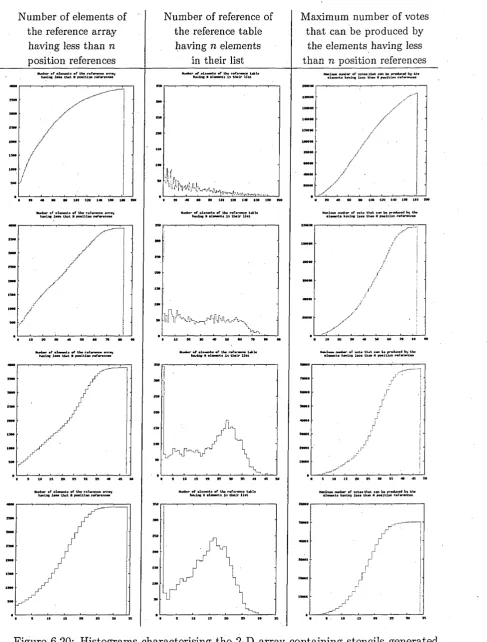
off-line for the hand shape. Each row corresponds to a different tuning of the area size of the stencils. These are 100 %, 56 %, 32 % and 18% of the references respectively... 123 6.21 Histograms characterising the 2-D array containing stencils generated
off-line for the hand shape. Each row corresponds to a different tuning of the area size of the stencils. 11 %, 6 %, 3% and 1% of the references respectively ... 124 6.22 Stencils for the hand shape. The z-axis represents the number of over
lapping stencils. Each row represents a different stencil decimation level corresponding to those of figure 6.20: 100%, 56%, 32%, 18% . . 125 6.23 Stencils for the hand shape. The z-axis represents the number of
overlapping stencils. Each row represents a different stencil decima-• tion level corresponding to those of figure 6.21 (11%, 6%, 3%, 1%)
and each column a different stencil . . . ... 126 6.24 Number of votes for each stencil. Each row represents a different
stencil decimation level corresponding to those of figure 6.20. Each column represents a different image from the hand image sequence . . 127 6.25 Number of votes for each stencil. Each row represents a different
stencil decimation level corresponding to figure 6.21. Each column represents a different image from the hand image s e q u e n c e ... 128 6.26 W hat has been termed average robustness is, in fact, the average
difference of, the number of elements of a stencil, and, the number of overlapping elements of its most overlapping s te n c il... 129 6.27 By total robustness we refer to the minimum, for all stencils, of the
.. robustness such it is explained in figure 6 . 2 6 ... 129 6.28 Time taken to track a shape versus the level of noise and the decima
tion ratio of the stencils for the hand image sequences . . ... 130 6.29 The graph of figure 6.28 from a different viewpoint. This shows how
the level of noise affects the tracking time ... '. . 130 6.30 The graph of figure 6.28 from a different viewpoint. This shows how
the stencil decimation ratio affects the speed performance of the trackingl31
off-line for the watch shape. Each row corresponds to a different tuning of the area size of the stencils. These are 100 %, 80 %, 60 % and 30% of the references respectively ... 133 6.32 Histograms characterising the 2-D array containing stencils generated
off-line for the watch shape. Each row corresponds to a different tuning of the area size of the stencils. These are 10 %, 5%, 3% and
1% of the references respectively . . . b ...134 6.33 Stencils for the watch shape. The 2-axis represents the number of
overlapping stencils. Each row represents a different stencil decima tion level corresponding to figure 6 .3 1 ...135 6.34 Stencils for the watch shape. The 2-axis represents the number of
overlapping stencils. Each row represents a different stencil decima tion level corresponding to figure 6.32 ...136 6.35 Number of votes for each stencil. Each row represents a different
stencil decimation level corresponding to figure 6.31 . Each column represents a different image from the watch image sequence... 137 6.36 Number of votes for each stencil. Each row represents a different
stencil decimation level corresponding to figure 6.32 . Each column represents a different image from the watch image sequence... 138 6.37 W hat has been termed average robustness is, in fact, the average of
the difference of, the number of elements of a stencil, and, the number of overlapping elements of its most overlapping sten c il...139 6.38 By total robustness we refer to the minimum, for all stencils, of the
robustness such it is explained in figure 6 . 3 7 ... 139 6.39 Time taken to track a shape versus the level of noise and the decima
tion ratio of the stencils for the watch image se q u e n c e s... . 140 6.40 The same graph as in figure 6.39 but with a different viewpoint. This
shows how the level of noise affects the tracking t i m e ... 140 6.41 The same graph as in figure 6.39 but with a different viewpoint. This
shows how the stencil decimation ratio affects the speed performance of the track in g... . 141 6.42. The tem plate is shown on the top left corner. The small black dots
are the particles. The centre of the square is the tracked location. . . 145
resents edge correlation measure. This is an ideal case where the measure gives a unimodal pdf. x and y axis are the pixel coordinates of the image point measured. It can be observed th at correlation mea sure is well localised which is a disadvantage for particle filters that are likely to sample the tracked object only on the neighbourhood of the object... ... 145 6.44 In spite of the blurred features of the pipette, its location is found.
Big black square dots are the peak points... 146 6.45 The heavy background clutter is illustrated by the existence of mul
tiple peaks in the graph. In spite of the heavy clutter the pipette tip is well localised through further evaluation of the peak points...146 6.46 A rare case where the tracking has failed. The centre of the square is
the tracked location. ... 147 6.47 The graph illustrates that most of the peak point obtained, though
the correlation of the edge template, are located around the pipette tip. But subsequent multivariate feature measure picked up the wrong
peak point as the probable location. ... 147 6.48 Another cluttered image, this one is due to the change of the back
ground of the pipette and illumination of the scene. The small black square points are the peak points. Centre of the square is the tracked location...148 6.49 The graph illustrates the background clutter which gives rise to mul
tiple peak points... 148 6.50 Last image of the tracking sequence. M agenta points are previous
tracked locations... 149 6.51 Actual location of pipette (line) and tracked location (crosses)...149
6.52 Number of tracked frames versus distance of actual location and tracked location... . 150 6.53 Actual location of pipette (line) and tracked location (crosses). Only
tracked location of points with high probability is displayed . . . . 150 6.54 Two images, from the pipette tip sequence. It is the same sequence
that was used to discuss the particle filter algorithm ...151
positions of the pipette tip when using our custom edge detector. . . 152 6.56 Comparison of the tracked positions and the manually determined
positions of the pipette tip using the Canny edge detector with the first set of param eters... 152 6.57 Comparison of the tracked positions and the manually determined
positions of the pipette tip when using using the Canny edge detector with the second set of param eters... 153 6.58 Comparison of the tracked positions and the manually determined
positions of the pipette tip when using using the Canny edge detector with the first setting and the motion filter. ... 154 6.59 Comparison of the tracked positions and the manually determined
positions of the pipette tip when using using the Canny edge detector with the second setting and the motion filter... 155 6.60 Tracking accuracy ...155 6.61 Tests carried out on an Intel Celeron Northwood 2.7 GHz CPU . . . 155
A .l An infinite number of squares can fit 3 points... 162 A.2 abed and abce are 2 four point convex configurations...164 A.3 For this configuration of four points we consider the 2 points furthest
apart. ... A.4 The green shaded square was constructed by assuming th at the 2
points furthest apart belong to opposite edges and the 2 remaining points to one of the edge. ... ...
A.5 It is not always possible to fit a square that intersects the 4 points using the assumption that the 2 points furthest apart belong to op posite edges and the 2 remaining points to one of the edge as shown with this configuration of four points. ... . A. 6 If the longest distance is an edge of the convex quadrilateral and we
assume th at the two remaining points belong to different edge of the square there exists at most two squares th at fit the four points. . . A.7 An example when the four points are fitted by a square assuming th at
the two points furthest apart are on opposite edges of the square and the remaining points belong to different edges. . . . . .
164
165
165
166
167
the plain black lines the four points can be separated into 3 groups: the point circled in green, the other point on the dashed green line and the two remaining points... 168 A.9 2 Points are taken randomly, by assuming th at they belong to op
posite edges, for instance, a system of equations can be w ritten and solved to check if it is possible to construct squares th a t are intersect ing this four points. Curved arrows represent the possible rotations of the parallel lines... 168 A. 10 8 points, any 3 of them not aligned, in a convex configuration can be
fitted by 2 quadrilaterals... 170
B .l The images seen by each eye are slightly different. Image from the
Optometrists Network website... 173
B.2 By obtaining the intrinsic parameter it is possible to determine where each point expressed in the camera frame will be projected onto the
image . . 173
B.3 A red parallelepiped and a white line projected on the image using the image formation m o d e l... ... . . ... 174 B.4 The right image is the rectified left image. Notice th a t the power
supply edge highlighted in previous figure appears straight...175 B.5 Top: pair of images taken by our stereo rig. Bottom: the same pair
after standardisation. Black lines have been drawn to exhibit the alignment of the corresponding image elements... 176 B.6 Pair of standardised image and their disparity map. Red points are
displayed when uncertainty is too high...177 B.7 Result of our implementation on a well known pair of standardised
images from the Tsubaka university repository. . ... 181 B.8 Different disparity maps using our calibrated images. . . . 182 B.9 Triangulation of a point... 182
C .l Tracking of a ping-pong ball. Top left corner, the ball tem plate image. The large white dots represent the previous tracked positions of the ball. The large black dot, the current position of the ball and the small white dots, the particles’ positions... 185
pong ball. The small white dots indicate the particles’ positions and
the larger white squares represent the earlier tracked positions... 185
C.3 After a few frame the tracking fails completely. . . . ... . . . 186
C.4 Different stage of the image filtering p ro c e s s ... 187
C.5 The filtered image with false colours... . 187
C.6 Tracking a Rubik’s cube, transparent white doted lines indicates the hypothesis location. . . 189
List of publications
1. M. Boissenin, J. Wedekind, A.N. Selvan, B.P. Amavasai, F. Caparrelli and J.R. Travis. Computer vision methods for optical microscopes. Image and Vision Computing, vol. 25, no. 7, p. 1107-1116, Elsevier Science Journal, 2007.
2. M. Boissenin, J. Wedekind, B.P. Amavasai, F. Caparrelli and J. Travis. Fast
pose estimation for microscope images using stencils. IEEE Systems, Man and
Cybernetics Society 5th Conference on Advances in Cybernetic Systems, p. 49-54, Septembre 7-8, 2006
3. K. C. Lim, M. Boissenin, B.P. Amavasai and R. Saatchi Development of a
desktop freehand 3-D surface reconstruction system, IEEE SMC UK&RI 6th
Conference on Cybernetic Systems 2008, London, UK.
4. J.Wedekind, B.P. Amavasai, K. Dutton, M. Boissenin A machine vision exten-,
sion for the Ruby programming language, proceedings 2008 IEEE, International
Conference on Information and Automation, 2008, Zhangjiajie, China.
5. J. Wedekind, M. Boissenin, B.P. Amavasai, F. Caparrelli and J. Travis. Object
recognition and real-time tracking in microscope images. IMVIP, 2006.
6. B.P. Amavasai, F. Caparrelli, A. Selvan, M. Boissenin, J.R. Travis and S. Meikle. Machine vision methods for autonomous micro-robotic systems. In Ky- bernetes Journal, vol. 34 no. 9/10 2005, ISSN 0368-492X.
7. M. Boissenin, B.P. Amavasai, J. Wedekind and R. Saatchi. Shape information:
using state space to select discriminative configuration of points. BMVA sympo
sium, Shape Representation, Analysis and Perception, November 5, 2007.
8. A. Eisinberg, K. Houston, F. Caparrelli, B.P. Amavasai, M. Boissenin and
manipulation. IEEE International Conference on Robotics and Automation (ICRA2006). Orlando, Florida, May 15-19, 2006.
9. A.N. Selvan, M Boissenin, B.P. Amavasai, F Caparrelli and J.R. Travis. Track
ing translucent objects in cluttered scenes. IEEE SMC Chapter Conference on
Cybernetics Intelligence-Challenges and Advances, 110-8, 2003.
10. R. Estana, J. Seyfried, M. Thiel, S. Johansson, N. Snis, J.M. Breguet, W. Driesen, T. Velten, J. Gao, P. Vartholomeos, S.G. Loizou, K.J. Kyriakopou- los, M. Boissenin, F. Caparrelli, J. Wedekind, A. Eisenberg, K. Houston, J. Samitier, M. Puig-Vidal, P. Miribel, A. Dieguez and H. Woern. The MiCRoN
Project, IST-2001-33567, March 2002 - February 2005.
Abstract
This thesis addresses the problem of tracking rigid objects in video sequences. A novel approach to reducing the tem plate size of shapes is presented. The reduced shape tem plate can be used to enhance the performance of tracking, de tection and recognition algorithms. The main idea consists of pre-calculating all possible positions and orientations th at a shape can undergo for a given state space. From these states, it is possible to extract a set of points th at uniquely and robustly characterises the shape for the considered state space. An algorithm, based on the Hough transform, has been developed to achieve this for discrete shapes, i.e. sets of points, projected in an image when the state space is bounded.
An extended discussion on particle filters, th at serves as an introduction to the topic, is presented, as well as some generic improvements. The introduction of these improvements allow the data to be better sampled by incorporating additional measurements and knowledge about the velocity of the tracked object. A partial re-initialisation scheme is also presented th at enables faster recovery of the system when the object is temporarily occluded.
A stencil estimator is introduced to identify the position of an object in an image. Some of its properties are discussed and demonstrated. The estim ator can be effi ciently evaluated using the bounded Hough transform algorithm. The performance of the stencilled Hough transform can be further enhanced with a methodology that decimates the stencils while maintaining the robustness of the tracker. Performance evaluations have demonstrated the relevance of the approach. Although the meth ods presented in this thesis could be adapted to full 3-D object motion, motions th at maintain the same view of the object in front of a camera are more specifically studied.
Acknowledgements
I wish to express my sincere gratitude to all the people th a t have contributed in some way or another to this thesis. I would like to first thank Dr J o n R . T ravis for giving me the opportunity and all the facilities to carry out this thesis to a successful completion.
I greatly appreciated the excellent supervision of Dr B a la A m avasai, his constant encouragements, his most valuable support and his much appreciated leadership by example. They have been constant sources of inspiration throughout my project. It has been a pleasure to work with Mr A ru l N ira i Selvan; his commitment to supporting me and his ongoing advice were of a great help.
I am deeply indebted to J a n W ed ek in d for his support and for sharing with me his software expertise. I have learnt a lot from him and the numerous discussions we had helped to shape the development of this thesis.
I would also like to express my gratitude to Dr R ez a S a a tch i for his kind support and his many helpful corrections and suggestions.
Many thanks to the examining committee: professor H u o sh e n g H u , professor M elv y n S m ith and professor C h risto p h e r C a re for reviewing my work and pro viding me extremely valuable feedback.
Thanks to A m ir, K im , S te p h e n and all the ERASMUS students th at stayed in the lab as well as all the people I have met in Sheffield who made life taste so much better and with whom I have spent good and great moments.
Finally, thanks to S u san who made me the marvellous present of touching my heart.
Chapter 1
Introduction
1.1 Rationale and motivation
“There is plenty of room at the bottom ” Richard R Feynman (1959)
The field of micro-manipulation and micro-robotics is in its very early stage of development and there only exist a handful of useful industrial applications within this area so far. It is predicted that in the near future a wider variety of application fields, from high-precision and fast assembly of mechanical micro-components in industry to the handling of cells in medical or biological applications will require ef ficient systems for micro-manipulation. Micro-manipulation systems promises many benefits for society as well as very high returns to the players th at will create the ' technology. To operate such systems require generic feedback. Currently, there are six main technologies. [2] than can estimate the pose of an object and track its motion:
• mechanical sensing, generally using electro mechanical transducers.
• inertial sensing usually through MEMS (micro-electronic mechanical systems).
• acoustic sensing with ultrasonic waves.
• magnetic sensing using captors th at measures the local magnetic field th at can be altered by using local sources.
• radio and microwave sensing on the time of flight principle.
• optical sensing using charge-coupled devices (CCDs).
Considering the size of the objects and their, environment visual feedback will be a key component in the realisation of micro-manipulation systems. These are amongst the major motivations for the work presented in this thesis.
The origin of the work th at is presented here is intimately related to and emerges from the development of two European union funded projects.
1.1.1 T h e M IN IM A N p ro je c t The main objective of the MINIMAN project [3] was the development of a sm art micro-robot with 5 degrees of freedom and a size of a few cubic cm, capable of moving around by the use of tube-shaped multi layered piezo-actuators. Controlled by visual and force/tactile sensor information, the micro-robot is able to perform manipulations with a motion resolution down to a few nano-metres (nm) in either a tele-manipulated or. semi-automated mode. The intention was to free humans from the tedious task of having to handle minuscule ob jects directly. Equipped with micro-machined grippers, the robot is able to perform high-precision grasping, transportation, manipulation and positioning of mechani cal or biological micro-objects, under an optical microscope or within the vacuum chamber of a scanning electron microscope. A powerful computer system using in expensive PC-compatible hardware components ensured the robot operation was carried out in real-time. The key to closed loop control was vision-based feedback. The vision system was used to locate objects and tools within the workspace. This project was successfully completed and was then followed by the MiCRoN project.
Figure 1.1: An artist impression of the MiCRoN project made for the project pro posal: mini robots, 1 cm across, working cooperatively in an assembly task
Figure 1.2: Overview of the MiCRoN set up during the integration stage. The camera is mounted on a Miniman robot. In the front, an infrared communication device is mounted on a USB port.
locomotion modules were integrated into a single miniature package.
1.2 Research aims and objectives
Figure 1.3: A tethered MiCRoN robot with its gripper under the microscope camera.
robot tools needed to be developed and the manipulated objects selected during the course of the project, the delivered vision system had to be generic enough to be adapted to the final objects that were used for the demonstration tasks of the project. Additionally, the pose estimation had to be done in real-time so that it did not become a bottleneck in the overall system. Moreover, since the system that took images was constrained in size, the image quality was impaired and the developed methodology had to be robust to these induced disturbances.
In order to address the real-time issue the focus was first put on tracking. To address the issue of adaptability the model of the object was built using an image of the object, the 3-D pose estimation was done with 4 degrees of freedom -2 sideways translations, orientation and depth of the object- and the robustness issue was dealt with by using a robust similarity measure.
1.2.1 C hoices an d discu ssio n One of the main topic of this thesis is tracking,
an important problem, since it has a wide range of applications (e.g. visual feedback,
data compression in videos, scene interpretation, etc), that has been extensively researched by the computer vision community.
Figure 1.4: The set up at Sheffield Hallam university, the camera support is mounted on a piezo-electric three degree of freedom translation stage. Green LEDs are used to illuminate the scene. Green has been chosen to avoid interferences with the infrared communication of the MiCRoN robots. 1 pixel in the obtained image corresponds to 1 micrometre (/mi).
position such as its previous estimated position and speed or the dynamics of the system. Some researchers advocate the terminology time coherence. Taking these considerations into account, object tracking is a process that consists in identifying sets of pixels in an image sequence that correspond to the same object. In contrast,
File Help ^ * □
6.63283 fram es/seco n d Eilename prefix stack
[image:31.612.346.470.92.266.2]Colour Contrast <V |20000 |f ] 132768 ^ |3 2 7 6 8 § |3 0 0 0 0 ^ j
l O Backward^ | u p | I Q Left |Q Right |
|Q Forw ard 11 Down |
— um | Update
— um Micro C am era
-JUIQ o
flbjects Type
□ follow object
000. ppm S tepsize
l*> In
um * im ages 1Tl[Figure 1.5: The graphical user interface of the recognition and tracking software.
The x-y axis frame indicates the position of the recognised and tracked syringe chip.
The image has been taken with a optical microscope and its quality is better than the images obtained with the MiCRoN camera.
Figure 1.6: The MiCRoN robot.
of the object. Recent improvements on the characterisation of features have made detection a viable alternative for locating objects in real-time. This should not be confused with recognition that intends to assign labels to image regions. These labels are generally drawn from a large number of labels representing different object
IR com m unication
m odule Electronics
Flexible PCB for interconnection Targets for
positioning system
Supporting Locom otion
structure m odule Arm actuator
M icrom anipulation tool
classes.
To estimate the position of an object some knowledge about the object and a way to use this knowledge with the image sequence is required. This leads to two interlinked issues: how to represent the object and how to m atch this representation in the image. As explained above, it was chosen to model this knowledge by using a sample image of the object, often called a tem plate image, taken in the first frame of the sequence. One way to locate the object in the scene image is to compare all parts of the image with the model i.e. to measure the similarity between parts of the image and the tem plate image. At this stage the following issues need to be addressed:
• Clutter: due to the limitation of the chosen measurement method, parts of the image can match well the object model even when the object is not present.
• Occlusion: the tracked object might be partly occluded, extend beyond the image, or, move beyond the image for a few frames. W hen it becomes visible again the algorithm should be able to locate it again.
• Noise: given a scene that does not change, the image acquisition system pro duces images that are slightly different. This is often due to limitations in the sensors or electronics. Comparison algorithms should be able to cope with these small variations th at can often be modelled by Gaussian noise.
• 2-D images of the 3-D world: the image acquisition process is not a bijective mapping; information about the scene is lost in the process, however supple mental information can be used to compensate for this loss.
• The slow evolution of the appearance of the tracked object due to changes in illumination, orientation and shape for deformable object.
• The search space, often due to its high number of dimensions, can be very large making the real-time objective challenging.
choice of this distance measure is crucial for reliable, robust and efficient tracking. If the measure is applied at any point of the image, a probabilistic density functions for the object location is obtained.
The observation that, in most applications, object motion is tightly bounded, i.e.
the object’s positions do not differ much between following frames, can be used to . achieve the real-time requirement. Moreover knowing the speed of an object or the characteristics of its movement can help to better predict the future object location.
The usage of statistical methods, namely Monte-Carlo methods, to estimate the location of an object has proved useful to reduce the search area. Note that since the matching has to be done in multiple locations, according to the algorithm used, parallelisation is likely to scale up well the speed of the tracking process.
In a class of algorithm the tracking process can essentially be divided into two sub-processes:
• A process to decide where to look. This restricts the search area and thus addresses the real-time objectives
• A process to decide how to look. This measure the probability of presence of an object.
One such technique that makes this distinction, and th at we explore in more detail in this thesis, is the particle filter. Chapter 3 provides a detailed discussion based on the implementation of particle filters to track a translucent micro-pipette tip.
This led to the main contribution of this thesis: tem plate reduction of point feature models. A novel framework has been introduced in order to reduce the number of points a point feature model requires to robustly and efficiently identify a shape in an image. Since fewer points are required the matching can be done more efficiently. Recognition, identification and tracking algorithm efficiency can benefit from this improvement.
In order to perform this tem plate reduction the state space of the object is considered: sets of points th at characterise a unique state of the object across the whole state space are reduced tem plate candidates. Constraints of robustness to missing feature points and additional feature points not corresponding to the object are also examined. A practical algorithm based on a generalised version of the Hough transform is presented to implement the tem plate reduction.
1.3 Research methodologies
A major part of the work undertaken in this thesis has consisted of developing and implementing algorithms. Implementations have been made publicly available on line as open source so th at it may be publicly scrutinised. Much of it can be found integrated into the Mimas [5] library.
Mimas is a C + + vision system toolkit built in-house, at Sheffield Hallam uni versity, with an emphasis on real-time applications. The library provides the in frastructure to load images from a wide range of formats due to the integration with other open source libraries such as the ImageMagick library, video by using the Xine library and cameras supporting Video for Linux and Firewire. Mimas also provides a number of low level image processing algorithms, such as edge/corner detection, disparity map, morphological operators or camera calibration. As well as higher level algorithms for object recognition and tracking such as geometric hash ing and particle filters. Various optimisation schemes, such as POSIX threads, are implemented in order to achieve the real-time objectives.
1.4 Contributions
The main contributions of this thesis, and its associated chapters are:
of point features for rigid objects. The framework considers the state space of an object in order to determine a subset of features of the original template th at characterises uniquely and robustly the state of the object across all the state space. An algorithm based on the Hough transform is used to select these features. An introduction to the problem and its formalisation is presented in chapter 4. M aterial presented in chapter 5 is closely related with the issue.
• A new shape estimator:the stencil estimator. It is shown how the estimator can be evaluated in an efficient manner using a variation of the Hough transform. This is presented in chapter 5 and an evaluation of the m ethod can be found in section 6.2.
• Generic improvements to the particle filter algorithm in the imaging context. An algorithm is introduced to cluster particles. Subsequent analyses follow ing the measurement process, th at evaluate the posterior probability density function of the state of the object, is discussed. These analyses can provide feedback to the particle filter to partially reinitialise the sampling of the par ticles. This is found in sections 3.5 and 3.6.
• Application of the the stencil estimator in a microscope environment where objects are subject to changes in appearance. Microscopes have a narrow depth of field and the features of an object changes with its distance to the microscope’s objective. This characteristic can be used to determine the dis tance of an object to the microscope’s objective by using a model of the object th at consists of a stack of images of the object taken at different depths. This contribution is presented in section 6.1.
1.5 Organisation of the thesis
Chapter 2 of this thesis presents a literature review focused on computer vision techniques related to the efficient identification and tracking of 2-D shapes in images.
The particle filtering algorithm is then presented on a concrete application, the tracking of a translucent pipette tip, and a few generic improvements are proposed in chapter 3.
state of a shape to be uniquely and robustly identified. The novelty consists of using the state space to select these characterising sets of points. This technique can be used during a pre-processing stage to obtain a more efficient representation of tracked objects.
In chapter 5 we present the stencilled Hough transform. The technique is a modification of the bounded Hough transform [6]. The introduction of the stencil estimator combined with a methodology to reduce the area of the stencils improves the speed and memory usage of the algorithm substantially, as shown by the test results presented in section 2 of chapter 6.
In chapter 6, experimental results are presented where the tracking of micro objects under a microscope was performed with 4 degree of freedom using a vari ation of the bounded Hough transform. In other experiments the bounded Hough transform and the the particle filter were compared on the tracking of a translucent pipette tip. Advantages and limitations of both techniques are discussed.
Chapter 2
Literature review
2.1 Introduction
Identifying a shape in an image is one of the fundamental problems in computer and machine vision. The Hough transform and the wide variety of techniques th at are derived from it are able to tackle this challenge to some extent. Other approaches include active contours [7] such as snakes [8] or level sets [9], matching techniques such as the inefficient cross-correlation coefficient [10] or boosted filters [11], and neural networks [12]. Each of them can outperform the others in specific application domains. While active contours can handle smooth deformable shapes that change, neural networks have been used extensively for hand-written character recognition. Boosted filters have been used for the recognition of object classes such as the human face whereas Hough transform techniques are well suited for rigid objects. Hough transform related techniques have been used, for many years now, to recognise 2-D objects in real-time on standard desktops. Although the shape of an object needs to be known, Hough transform related techniques do not need to be trained, are resistant to noise and partial occlusions and can accurately determine a specific object location.
Choosing the right technique for a given application, although essential, is not straightforward given the wide choice of techniques currently available. One of the major concerns, th at has to be kept in mind and may help in this choice, is the real-time constraint. Indeed, the machine vision system should not be a bottleneck in the application th at it is embedded into and, as a consequence, should be as fast as possible. A general way to speed up object location algorithms is to constrain
the search area. Computational costs tend to increase dramatically with the size of the search area. To constrain the search area a number of techniques can be used. Nevertheless, they share a common trait: to utilise the object’s previous location or, more accurately, its estimated location and some knowledge of the object motion.
These techniques are commonly referred to as tracking techniques. From a util itarian point of view tracking has to deal with a number of issues th a t have been presented in section 1.2.1, page 5, and will be further examined on a practical ap plication in section 3.3, page 40. A few different approaches to tracking will be discussed in the visual tracking section of this chapter. One group of approaches consists in distinguishing a component that selects the locations where to look for the object from a component th at identifies the object. W hen this distinction is possible, tracking often refers to the first stage of these approaches.
Nevertheless to be able to track an object its initial position has to be determined, the review is started by presenting the initialisation stage, this stage can make use of an approach th at is often overlooked: motion detection, and when the background remains stable background subtraction.
In this thesis, we deal mostly with tem plate matching as the identifying method,
i.e. the usage of an image of the object to identify its characteristics in another image which is usually larger and th at contains other elements. However other methods exists, for instance, the usage of param eter or generative models [13] could be used. Moreover, the focus has been put on matching techniques th at are feature based. The underlying assumption being th at by reducing the data from colour images to a set of features, the data may be more efficiently utilised. This is arguable and discussed in Zitova and Flusser [14], who provide a survey on image registration techniques. The efficiency of determining the characteristics of an object in an image depends on:
• how discriminative the features are i.e. how many of them are needed to determine the characteristics of an object.
• the cost of evaluation of these features.
• how features are compared and used to determine the object characteristics.
topic of research. Some elements that have to be considered will be discussed in this thesis. More specifically, the issue of reducing an object representation that consists of feature points while keeping a discriminative object representation will be tackled.
Another approach th at has been the focus of research for the matching of tem plates is the hit-or-miss method which emerged from the field of m athem atical mor phology. A review of this approach is provided in this chapter.
There are many other alternatives to characterise, represent and analyse shapes, Loncaric [15], in a not so recent survey, presented a number of these techniques. This survey can serve as an introduction to shape analysis. Walker, Cootes and Taylor [16] proposed another interesting alternative for 2-D object representation: the use of salient features to track an object in a video sequence and automatically build its appearance model [17][18]. As previously mentioned our focus is on feature points representation, techniques to match point sets are reviewed in the section justly named: techniques to match point sets.
Distortions can be quite common when working with custom cameras and mi croscopes. A few issues related to image distortions as well as how to handle them are presented.
The main results of this thesis are related to the Hough transform, hence after an introduction presenting a generalised Hough transform the link with tracking is established and more advanced topics, which are related to the work, are then discussed in the last section. They deal with improvements to the original Hough transform algorithm.
2.2 Connected techniques to visual tracking
2.2.1 D e te c tio n a n d in itia lisa tio n Tracking essentially makes use of the pre vious position of the object to reduce the search space where the object is searched for in the next frame. However, the object has to be located in the first frame. Moreover, when the tracking fails, a recovery system needs to be used to locate the object again. For these two reasons, it is practical to use a tracking algorithm in combination with a detection algorithm.
assumption on its probable location. Detection algorithms may be simpler to imple ment, but they come with a cost penalty in terms of efficiency due to the fact that im portant informations such as the previous location of the object are discarded. As usual, the choice depends on the resources available (computational power, time,
etc.) and the application under consideration.
Nevertheless, when multiple instances of the same object are present, such as cars on a motorway or people in underground transport, tracking cannot be replaced entirely by detection when the object identity needs to be known.
2.2.2 B ac k g ro u n d s u b tra c tio n a n d m o v em en t d e te c tio n For the problem of initialisation a very useful cue is the object’s motion. If the background is not moving or if its appearance is stable (of uniform colour, for instance) then object features can be selected by subtracting features in the background. A review of background subtraction techniques is provided by Piccardi [19].
Sugrue and Davies [20] developed an original approach which consists of applying a 3-D spatio-temporal filter on a stack of sequential images to detect motion. Its advantages over background modelling techniques are that no information from the background is needed, which makes it faster. The technique is also inherently robust to noise.
2.2.3 M a th e m a tic a l M o rp h o lo g y Ronse, Naegel and Passat [21] [22] [23] pre sented a very impressive and elegant theoretical framework by combining multiple research strands on tem plate matching using the tools of mathem atical morphology and their generalisation for grey-level images. The algebraic approach has its lim itations though, it focuses more on the exactitude of the methodology rather than performance evaluation and implementation issues.
The literature is very scarce in algorithm implementation and performance com parisons. Using the openCV library a few tests were run. For a colour image of 512 x 512 (~ 250000) pixels on an Intel Core 2 Duo (T5450) 1.66 GHz (~ 3300 bogomips) the approximated processing times are given in the following array:
Diameter of the structuring element
3 5
Opening or closing operator
180 ms 230ms
Erode or dilate operator
95 ms 140 ms
It can be seen th at morphological operators can be time consuming. To cir cumvent this issue different approaches have been taken: using field-programmable gate arrays (FPGA), using optical processors, but the most promising approach . might be, because of its future availability and sheer processing power, to make use of GPGPUs (General-Purpose computation on Graphical Processor Unit) such as
CUD A (Compute Unified Device Architecture) enabled GPUs.
One of the main advantage of expressing tem plate matching in terms of morpho logical operators is th at they can be implemented on hardware like FPGA. Baumann and Tinembart [27] provide an overview of the tools and insights in the methodology that could be used to implement morphological operators on a FPGA. A hardware implementation is also discussed in [25].
The literature also contains references to an optical implementation [28], i.e. by using an optical processor however this is beyond the scope of this review.
A notable issue with morphological operators is th at they are translation in variant operators relative to a structuring elements. In [23], which presents an application for the segmentation of blood vessels from 3-D angiographic1 data, this issue is circumvented by rotating the structuring elements.
2.2.4 T ech n iq u es to m a tc h p o in t se ts The selection of a measure to identify an object depends on its properties and its motion. Different techniques may be more or less suitable and efficient when an object is deformable and moving in a 3-D
space, or rigid and undergoing 2-D translations. If practical results are expected, identifying these characteristics is critical for the selection of an efficient technique.
W hen distortions, due to an imperfect lens can be neglected, the transforma tions th at a 2-D plane undergoes can be modelled by projective transformations. Moreover, when the object is small compared with its distance to the camera and if it moves by a small distance according to the same criteria, perspective effects can be neglected and the object features can be put into correspondence using affine transformations. An affine transformation of the plane consists of a linear transfor mation followed by a translation. An affine transformation can be considered as a composition of a dilation, a rotation, a shear and a translation. Note th at lengths and angles do not remain the same under affine transformations. The affine trans formation subset th at have these properties is called the similarity group; it consists of the Euclidean transformations and the mirror transformation.
Gope and Kehtarnavaz [29] provided a review of affine invariant comparison techniques of point sets. They also described a technique where an image point set and a tem plate point set are compared relatively to an affine transformation. In order to do that the parameters of the affine transform ation are evaluated by determining affine invariant points for both sets of points and comparing them. Then the match is validated using an enhanced Hausdorff distance method. Finally, the technique is compared, using a dataset, to three popular affine invariant techniques. The outcome is favourable for the presented technique and dataset in terms of efficiency, noise and occlusion resistance. The Hausdorff distance between two sets of points U and V is defined as:
R ( U ,V ) = m a x ( h { U ,V ) M V ,U ) ) (2.1)
where
h(U, V) = m axm in ||w,u|| (2.2)
u€U v&V
In order to cope with occlusions and outliers different schemes have been used in stead. For instance instead of using the maximum, the kth ranked distance can be used. The paper proposes an interesting variation of the Hausdorff distance. For more details on the Hausdorff distance and its implementation the reader may also refer to [30].
However the measure could be adapted by taking into account an additional criteria, such as colour for instance, conditioning the evaluation of the distance of points belonging to the two sets U and V. Combining global geometric characteristics with local appearance characteristics of an object is an idea th at can greatly improve reliability and efficiency of many measures. Many interesting studies examining the synergy of these two fundamental aspects of object identification could be done.
A useful mathematical structure to represent and manipulate transformations of the general affine group, GA(2), or the projective transformations in R 2, where P(2), is the Lie algebra [31][32][33]. It allows the separation of different components of a transformation in terms of, for instance, translation along the x and y axes, rotation, dilation, shear and shear at 45 degrees. This is valuable when these information are needed by a system like a robotic arm [33].
Another useful technique to compute corresponding sets of points is the Chamfer distance. It consists in evaluating the distance of a pixel to its closest feature points. Such a distance map can be evaluated efficiently [34]. It allows the usage of optimisation algorithms using gradient techniques such as Levenberg-Marquardt to minimise an energy function th at characterises the matching of two sets of points.
In Robust Registration of 2-D and 3-D Point Sets [32] Fitzgibbon has compared the iterative closest point (ICP) algorithm and a Levenberg-Marquardt based al gorithm. These techniques require a previous approximation of the location of the object and are therefore well suited for tracking when the. object position does not change significantly from one frame to another.
Breuel [35] [36] presented a technique to match geometric primitives, such as points, given a transformation space. The techniques based on branch-and-bound methods finds a global optimal solution to the matching problem. It works by recursively subdividing the transformation space and computing the upper bound of the number of points that can be potentially mapped by a transform ation of a sub transformation space. This is referred to as the matching quality of the sub-region and denoted by Q(T). The computation of the bound of Q(T) for a transform ation space T is easy, th at is why the technique works well, for more details on this point refer to the paper. The technique is exhaustive and guarantees a globally optimal solution to the geometric matching problems.
1. The algorithm maintains a priority queue of search states. W hen two search states have the same priority, the state with the higher depth in the search tree is preferred. The queue is initialised with a state representing all possible solutions.
2. Each search state T* is associated with a sub-region of the transformation space Tfc C ¥ 0«. It is further associated with an upper bound such that VT G Tfc : Qk = Q(¥fc) > Q(T)\ the upper bound serves as the priority of the state. For termination and correctness, the upper bound needs to satisfy that the sub-region is small enough and that its quality still remains above a given pre-determined threshold.
3. The algorithm removes the state with the highest upper bound from the pri ority queue. In case of ties, states with higher depth in the search tree are preferred. Breuel showed th at depth first search is almost as fast as breadth first and uses only a tiny fraction of memory.
4. The transformation T G T*; if Q{T) = Q(Tk), terminates the search and returns T as a solution.
5. Otherwise, the region ¥*, is split into two disjoint sub-regions ¥2*; and ¥2/0+1
such th at Tk = ¥2^ U ¥2^+1 along its largest dimension. Q{T2k) and Q(T2k+1)
are evaluated and these sub-regions are inserted back into the priority queue.
of the object is evaluated. The operation is iterated until the time allocated has expired or enough evidence has been accumulated to estimate the object position beyond reasonable doubt. Our experiments have shown that, for the example we mentioned, the first match is sufficient. Details of our implementation is available in Wedekind et al. [37]. The method has been extended to recognise objects using focus stacks, allowing the distance of the object from the lens of a microscope to be estimated.
As mentioned in the introduction there are other alternatives for identifying a shape. One of these alternatives is the use of moments. Moments [38] can be ef ficiently evaluated [39] and can provide a compact representation of a shape by characterising its global features. For instance, using the moments up to the sec ond degree a shape can be approximated by an’ellipse. Many applications in image analysis have been found for them: object classification, pose estimation, pattern recognition and compression. However, the global characterisation of a shape is not robust to occlusion which reduces its application domain to specific but neverthe less useful environments, for visual servoing for instance. Even though moments can not be used to characterise the global shape of an object in case of occlusion, by characterising local patches, for instance by using the orthogonal and rotation in variant Zernike moments [40], the global pose of an object can still be efficiently and robustly determined. Thus moments can be used to characterise features. Having distinguishable features redefines the problem of matching sets of feature points and reduces drastically its complexity [41]. In appendix B.2 other feature characterising methods are mentioned.
2.2.5 Im ag e d is to rtio n It is not uncommon th at the lens system of microscope produces image distortions. To correct them, so th at the shape of an object remains the same independently of its position within an image, the image acquisition system has to be modelled. In most cases, distortions exhibit a central symmetry on the principal point of the image th at can be corrected by an adequate mapping of the image.
characteristics of each camera. The process of determining these parameters is known as camera calibration.
Camera calibration is still a