How To
Select The
Right
Laboratory
Hood System
Foreword
This booklet has been developed to serve as an aid in selecting a laboratory fume hood ventilation system. The information is intended to be unbiased and generic in nature, compiled with help from experi-enced architects, laboratory consultants, engineers and laboratory hood users. The basic understanding of hood systems you gain from reviewing this book-let should prove valuable to you as you discuss your needs with safety officers, engineers and hood manufacturers.
Our Method
The table of contents outlines the various issues which are addressed in this booklet. As you read through the material, remember you are selecting a laboratory hood system. A fume hood does not function alone. A variety of factors external to a hood influences its performance. Likewise, a hood and the applications performed inside it can also affect its surroundings. When selecting a fume hood, you must consider the whole picture — the labora-tory space, the building’s ventilation system, the hood’s location in the room, to name a few.
While this booklet will raise the questions neces-sary to identify your specific hood requirements, it may not answer those questions. Only you, your safety officer or industrial hygienist, and a qualified design consultant can identify your laboratory’s unique challenges.
We want this document to expand and improve over time. If you have suggestions for additions or improvements to this guide, please write Labconco Corporation, 8811 Prospect Avenue, Kansas City, MO 64132. Or call 800-821-5525 or 816-333-8811.
Table of Contents
Page NumberSelecting The Proper Enclosure
What is a Laboratory Fume Hood 3 Laboratory Exhaust Systems and
Types of Laboratory Hoods
Constant Volume — Conventional, By-Pass,
Auxiliary-Air, Reduced Air Volume 3-4
Variable Air Volume 4
Special Application Laboratory Fume Hoods
Perchloric Acid Hoods 5
Radioisotope Hoods 5
Distillation and Walk-In Hoods 5-6 Not All Enclosures are Laboratory Hoods
Canopy Hoods 6
Downdraft Hoods 6
Ductless Carbon-Filtered Enclosures 7 Biological Safety Cabinets and
Other HEPA-Filtered Enclosures 7
Clean Benches 7-8
Glove Boxes 8
Laboratory Hood Specifications
Hood Size 8
Liner Material 8-9
Sashes 8-9
Explosion-Proof vs.
Non Explosion-Proof Hoods 10
Service Fixtures 10
Electrical Receptacles 10
Lighting 10
Americans with Disabilities Act Requirements 10-11 Performance and Installation Considerations
Face Velocity and Containment Issues 11 Proper Techniques for Hood Use 12 Ventilation System Components and Accessories
Remote Blowers 12-13
Blower Sizing 13
Integral Motor/Blowers 13
Airflow Monitor 14
Exhaust Air Treatment 14
Ductwork 15
Base Cabinets 15
Work Surfaces 15
Sash Stops 16
By-Pass Blocks 16
Sash Position Alarms 16
Fire Extinguishers 16
Renovating Existing Laboratory
Fume Hoods and Ductwork 16
Planning Laboratory Space
Laboratory Layout 16
Sufficient Room Air 17
Energy Conservation 17
Noise Control
Conclusion 17
Laboratory Ventilation Standards 17-18
General References 18
Selecting The Proper Enclosure
What is a Laboratory Fume Hood?
A laboratory fume hood is a ventilated enclosure where harmful or toxic fumes or vapors can be han-dled safely. The purpose of the hood is to capture, contain and remove contaminants, preventing their escape into the laboratory. This is accomplished by drawing contaminants within the hood’s work area away from the operator, so that inhalation and con-tact are minimized.
Airflow into the hood is achieved by an exhaust blower which “pulls” air from the laboratory room into and through the hood and exhaust system. This “pull” at the opening of the hood is measured as face velocity. A baffle, air foil and other aerodynamically designed components control the pattern of air moving into and through the hood. Contaminated air within the hood is then diluted with room air and exhausted through the hood’s duct system to the outside where it can be adequately dispersed at an acceptably low concentration.
Laboratory Exhaust Systems and
Types of Laboratory Hoods
All laboratory fume hoods’ operational airflow can be described as one of two types: conventional and by-pass. Auxiliary-air and reduced air volume hoods are variations of the by-pass hood. Hoods use one of two kinds of exhaust systems: constant volume or variable air volume.
Constant Volume
Conventional
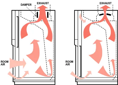
The conventional hood is a basic enclosure with an interior baffle and movable front sash. The conven-tional hood generally operates at a constant exhaust
volume with the majority of exhaust air entering the hood through the sash opening. Closing the sash increases the speed of the air through the sash open-ing so that high face velocities are to be expected with the sash in the near closed position (Figure 1).
The conventional hood is generally the least expen-sive, but its performance depends largely on sash position. With the sash in the near closed position, high velocity air passing through the sash opening can damage fragile apparatus, disturb instrumenta-tion, slow distillation rates, cool hot plates, disperse valuable sample materials or result in turbulence inside the hood.
By-Pass
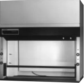
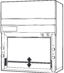
The by-pass hood generally operates at a constant volume and is designed so that as the sash is closed, the air entering the hood is redistributed, thereby minimizing the high velocity air streams encoun-tered in conventional hoods. The by-pass openings above and below the sash area reduce fluctuations in face velocity as the sash is raised or lowered (Figure 2). Therefore, the face velocity in by-pass hoods does not generally reach levels which might be detrimen-tal to lab fume hood procedures. By-pass type hoods comprise the majority of hoods on the market. Protector®60 Fiberglass Laboratory Fume Hood
EXHAUST EXHAUST
ROOM AIR
[image:3.504.55.203.218.364.2]ROOM AIR
Figure 1. Conventional hood with sash open and nearly closed
EXHAUST EXHAUST
ROOM AIR
[image:3.504.257.451.554.695.2]ROOM AIR
Auxiliary-Air
A variation of the by-pass hood, the auxiliary-air hood offers a means of providing up to 50% of the air for the hood exhaust from outside the laboratory, and limits the volume of tempered air removed from the laboratory (Figure 3). This hood type has many names including induced air, add-air, balanced air and make-up air.
One advantage to auxiliary air hoods is that they feed air-starved laboratories, where room supply air volume is not adequate to support a laboratory hood. Another advantage to auxiliary-air is that, when prop-erly applied, it can provide energy savings by limiting the volume of heated or cooled room air exhausted by the hood. The level of savings depends on the degree to which the auxiliary air must be tempered.
Certain negative aspects of auxiliary-air hoods should be considered. Because two blowers and two duct runs are required, initial equipment and set-up costs are higher than average. Since an oversized aux-iliary-air system may overpower the exhaust system, auxiliary-air systems require careful balancing to prevent undesirable turbulence at the face of the hood. In addition, temperature extremes, caused by untempered auxiliary air, can adversely affect the hood’s containment ability and cause user discom-fort. Finally, the auxiliary air should be clean, dry and tempered properly so it does not interfere with analytical work being done in the hood.
Reduced Air Volume
A variation of the by-pass hood, the reduced air vol-ume (RAV) hood uses a by-pass block to partially obstruct the by-pass opening above the sash to reduce the air volume exhausted thus conserving energy. It is used in conjunction with a sash stop that limits the height the sash may be opened during nor-mal use so that the hood demands less air volume to achieve safe velocity. Since these hoods use less air
volume than by-pass hoods of the same size, they require smaller blowers, which can be another cost saving advantage.
RAV hoods should be used with caution. The sash stop should be overridden only when loading or cleaning the hood; never while in use. If the sash stop is disengaged and the sash raised while the hood is in use, the face velocity could drop to an unsafe level (Figure 4). A sash position alarm is recommended.
Variable Air Volume
Variable air volume (VAV) hoods vary the amount of room air exhausted while maintaining the face velocity within a preset range. VAV hoods alter the exhaust volume using various methods. One method utilizes a damper that opens and closes based on airflow and sash position. Another method involves varying blower speed to meet air volume demands. When multiple hoods share one common exhaust blower, both methods may be utilized.
Fume hoods with VAV systems generally operate as conventional hoods. Some VAV hoods include a modified by-pass system which ensures that suffi-cient airflow is maintained to adequately contain and dilute fumes even at low sash positions (Figure 5).
AUXILIARY OUTSIDE AIR
EXHAUST
ROOM AIR
AUXILIARY OUTSIDE AIR
EXHAUST
[image:4.504.44.244.175.328.2]ROOM AIR
Figure 3. Auxiliary-air hood with sash open and closed
EXHAUST EXHAUST
ROOM
AIR ROOMAIR
DAMPER
Figure 5. Variable air volume hood with damper control and modified by-pass
EXHAUST
ROOM AIR
EXHAUST
ROOM AIR BY-PASS
BLOCK
[image:4.504.261.457.183.325.2]SASH STOP
[image:4.504.263.457.544.685.2]VAV systems are available built into the hood at the factory or as an accessory added to the hood upon installation. Some VAV hoods have electronics which allow them to be connected to the laboratory build-ing’s heating, ventilation and air conditioning (HVAC) system for monitoring hood exhaust air and control-ling laboratory air supply from a central location.
Although initial start up costs may be higher due to building alterations, VAV hoods offer energy savings over traditional by-pass and auxiliary-air hoods. At the same time, they offer consistent airflow regardless of sash position so they are a good choice for complicated or lengthy experiments. In addition, most VAV systems feature monitors/alarms which alert the operator to unsafe airflow conditions.
Special Application Laboratory
Fume Hoods
Unique features may be added to the hood and exhaust system to accommodate special procedures in the hood. Below are descriptions of a few of the many special purpose hoods on the market.
Perchloric Acid Hoods
Perchloric acid hoods are dedicated for use with per-chloric acid only. Organic materials should not be used in a perchloric acid hood because an explosion may occur when perchloric acid reacts with organic materials. It must be constructed of relatively inert, impervious materials such as Type 316 stainless steel, Type 1 unplasticized polyvinyl chloride (PVC) or ceramic-coated material. Hoods used for these appli-cations have integral work surfaces, coved interiors, and a drain for easy and thorough cleaning. Washdown features are required since the hood and duct system must be thoroughly rinsed after each use to prevent the accumulation of potentially reactive perchloric salts. (Figure 6). Horizontal duct runs and sharp turns should be avoided so that washdown residue drains thoroughly. Each perchloric acid hood requires its own dedicated exhaust system with washdown capability.
Radioisotope Hoods
Hoods used for radioactive applications have integral work surfaces and coved interiors to facilitate decon-tamination. Liner materials, such as Type 304 stain-less steel, should be impermeable to radioactive materials. Cupsinks are sometimes provided in the integral work surface, however local codes which dictate the safe disposal of radioactive effluents should be observed. These hoods should be sturdy enough to support lead shielding bricks in instances where they are required. They should also be installed to facilitate the use of high efficiency partic-ulate air (HEPA) or charcoal filters in the ductwork. The laboratory’s safety officer should determine which, if any, filters are required to trap the radioac-tive materials emitted during a particular application.
Distillation and Walk-In Hoods
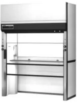
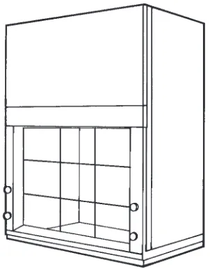
[image:5.504.301.395.39.261.2]Distillation and walk-in hoods are constructed with additional interior height to accommodate large apparatus. Distillation hoods typically mount on a platform instead of a base cabinet or bench. A California hood is a type of distillation hood with sash entry on both sides (Figure 7). Walk-in hoods mount on the floor, permitting roll-in loading of heavy or bulk apparatus. Although called walk-in hoods, the operator should never stand inside the hood while fumes are being generated.
Not All Enclosures Are
Laboratory Hoods
There are many enclosures designed to protect the operator from exposure to potentially hazardous substances. Other enclosures function to protect the samples contained inside. Although in some instances they may look similar to fume hoods, these containment devices have different modes of opera-tion and different uses.
Canopy Hoods
Canopy hoods are designed to remove steam, heat or odors from large or bulky apparatus such as ovens,
steam baths or autoclaves. Vapor removal is most efficient when the canopy is mounted no more than 12" above the equipment being ventilated. Because it is inefficient and ineffective in containing fumes, the canopy hood is not recommended for ventilating hazardous substances.
Downdraft Hoods
Like fume hoods, downdraft hoods draw air into the face of the hood. Unlike fume hoods, the blower is usually mounted below the hood work area so that air is pulled down through a mesh work surface and then exhausted to the outside (Figure 8). Downdraft hoods are used for applications involving heavier than air gases and materials such as dusts and powders. In some cases, these materials are recovered for reuse.
Protector®60 Fiberglass Walk-In Hood
[image:6.504.64.219.68.275.2]Canopy Hood
[image:6.504.263.457.146.323.2]Figure 8. A downdraft hood designed for removing powders generated by grinding metals or plastics
Ductless Carbon-Filtered Enclosures
As the name implies, ductless enclosures are not con-nected to an exhaust system. They rely on filters to trap vapors and fumes before air is recirculated to the room. The filters are usually made of specially treated or activated charcoal media that treat or adsorb chemical fumes including certain organic sol-vents, ammonia, acids and formaldehyde. Filter types and capacities can vary widely between manufactur-ers. Since these enclosures recirculate filtered air back into the laboratory, they often have a built-in mecha-nism to alert the user to unsafe concentrations of chemicals detected in the exhaust area of the filters.
Filtered enclosures can provide a practical solu-tion for laboratories where ducting may not be feasible. Due to the cost of replacing saturated filters, these enclosures are recommended for applications involving only small quantities of chemicals. Since different filters may be required for different chemi-cals, the enclosures are generally limited to repetitive applications and procedures involving a limited number of chemicals. Special consideration should be given if the chemical fume is highly toxic or car-cinogenic. Careful and regular monitoring by a safety officer is essential to the safe operation of these enclosures.
Biological Safety Cabinets and Other HEPA-Filtered Enclosures
Although often referred to as “hoods,” Class II bio-logical safety cabinets are not fume hoods. Biobio-logical safety cabinets are designed to contain hazardous particulates such as bacteria and viruses and often recirculate cabinet air back to the laboratory. Biological safety cabinets use HEPA filters to trap particles while any gaseous materials pass through
freely. When exhausted to the outside, they can accommodate trace amounts of toxic chemicals and radionuclides. If the work involves infectious or car-cinogenic agents and personnel and product protec-tion are required, then a biological safety cabinet is probably the enclosure of choice. Other HEPA-filtered enclosures, including Class I enclosures, that provide only personnel protection are designed for applications including weighing powders or handling asbestos. For an in-depth discussion on HEPA-filtered enclosures including Class II safety cabinets and Class I enclosures, request the publication,
Personnel and Product Protection: A Guide to Biosafety Enclosures, by calling 800-821-5525 or 816-333-8811.
Clean Benches
Clean benches are devices which use a blower to force room air through a HEPA filter, and over a work surface. This vertical or horizontal laminar flow of filtered air protects the work from particulate contamination. The major limitation of clean bench-es is that they provide only product protection; the operator is constantly exposed to any aerosols gener-ated by the work being performed. Consequently, hazardous materials should never be handled in a clean bench. Clean benches were developed as part Paramount™Filtered Enclosure
of “clean room” technology and are widely used in the electronics and pharmaceutical industries. They have also been successfully used in research laborato-ries for tissue culture and media preparation, and in hospitals and pharmacies for drug preparation.
Glove Boxes
Glove boxes consist of a sealed chamber with glove ports and gloves for handling materials inside, a viewing window for observing, and transfer chamber or door for loading and unloading. Because they provide a physical barrier between the operator and the substances inside, glove boxes are appropriate for applications that require the greatest protection against inhalation of substances used within them. Glove boxes for hazardous materials such as low level radioisotopes and carcinogens filter the chamber air prior to exhausting it through a duct system to the outside. Other glove boxes used for containing atmosphere-sensitive materials may or may not be ducted to the outside.
Laboratory Hood Specifications
Hood Size
The working space inside a laboratory hood is defined as that part of the hood interior where appa-ratus is set up and vapors are generated. This space normally extends from behind the plane of the sash(es) to the face of the baffle, and up from the work surface, 34" to 48". The working space required determines the width of the hood needed. One source recommends that 5 linear feet of hood space be provided for every two workers if they spend most of their time working with chemicals.
Laboratory hood sizes are commonly expressed by the outside width and not by working space. The most common hood widths are 3, 4, 5, 6 and 8 feet. Custom designed fume hoods may have widths up to 24 feet. The actual working space is approximately 5" to 10" less than the expressed width of the hood.
Liner Material
The liner material selected should be durable and resist chemicals, heat and open flame. A description of common liner materials and their characteristics follows (Table 1). The best liner material for a hood should be determined by the applications, types and concentrations of chemicals that will be handled in the hood and exhaust system. Laboratory hood efflu-ents may be classified generically as organic or inor-ganic chemical gases, vapors, fumes or smokes — and qualitatively as fume acids, alkalis, solvents or oils. Hood liners are subject to attack from such effluents by: (1) corrosion (the destruction of metal or other material by chemical or electrochemical action), (2) dissolution (a dissolving action to which coatings and plastics are subject), and (3) melting (occurs with certain plastics and coatings at elevated operating temperatures). The effect of any deconta-mination materials on the hood liner should also be considered.
Working temperatures inside the work space also affect the selection of liner materials. Certain codes and insurance underwriters have flame and smoke spread rating requirements which establish pre-scribed limits to applicable materials. Most local environmental authorities have codes which incor-porate standards based on NFPA Standard No. 45, Fire Protection for Laboratories Using Chemicals.
Sashes
Sashes provide some physical protection from splashes and reactions, and are transparent to allow viewing. Sashes rise vertically, slide horizontally or combine both horizontal and vertical characteristics Purifier®Horizontal Clean Bench on Base Stand
Protector®Controlled Atmosphere Glove Box on Mobile
in a design known as an “A-style” sash (Figures 9, 10 and 11). Sash configuration selection is a matter of preference. Vertical rising sashes are the most popu-lar and allow popu-large apparatus to be loaded in the hood. Horizontal sliding sashes allow the operator to reach around both sides of the sash while using the sash as a shield. Because the sash opening is
smaller, they conserve energy by limiting the volume of air exhausted.
[image:9.504.51.458.75.448.2]Safety glass is the most common and economical choice for sash material. Polycarbonate sashes are recommended when hydrofluoric (HF) acid is used since this material does not fog or etch when exposed to HF fumes.
Table 1. Hood liner materials
Stain Moisture Chemical Heat Flame Other
Resistance Resistance Resistance Resistance Resistance Comments
Epoxy-coated Good Very good Good Very good Good, Care must be taken
steel but will char to avoid damaging
coating since corrosion can occur in damaged areas. Inexpensive. Epoxy-resin Good Excellent Excellent Very good Good Not easily modified.
Brittle, requires care in handling. Expensive. Fiberglass Good Excellent Very good for Good Good Excellent light reflective
reinforced a wide range of properties. Moldable
polyester acids, solvents to eliminate seams and
(FRP) and alkalis crevices. Easily
modified. Moderately expensive.
Glass Fair Fair Very good for Excellent Excellent Good
sound-dampen-reinforced a wide range of ing qualities. Heavy.
cement acids, solvents Inexpensive. Brittle,
(GRC) and alkalis requires care in
handling. Poly- Very good Excellent Excellent Poor Fire-retardant, Easily modified.
propylene but poor heat Poor heat resistance.
resistance Expensive. Polyvinyl Very good Excellent Excellent Poor. Fire-retardant, Easily modified. chloride except for Will distort but poor heat Well-suited for sulfuric
(PVC) some solvents at 160° F resistance and acid hydrofluoric
digestions. Expensive. Solid Good Excellent Excellent Very good Excellent Excellent light
reflec-composite tive properties.
Well-panel suited for corrosive
materials. Moderately expensive. Stainless Good Excellent Good resistance Excellent Excellent Primarily used for
steel to a wide range, special applications
(Type 316 subject to attack involving perchloric
or 304) by some acids acid or radioisotopes.
Heavy. Difficult to modify. Expensive.
Figure 9. Hood with vertical-rising sash Figure 10. Hood with horizontal-sliding sashes
[image:9.504.62.168.567.688.2]Explosion-Proof vs. Non Explosion-Proof Hoods
An explosion-proof hood may be required for pro-tection when specific concentrations of flammable or explosive materials are to be used. An explosion-proof hood is defined by most manufacturers as a laboratory hood equipped with specially designed electrical components, such as explosion-proof light fixtures. Explosion-proof does not mean that the hood is capable of containing or withstanding an explosion. Rather it means that electrical compo-nents are designed to eliminate sparks and prevent the escape of flame or heat that could ignite flamma-ble materials. An explosion-proof hood’s electrical components, such as explosion-proof switches, receptacles and internal wiring, are supplied and installed on site by a licensed electrician in order to meet all state and local codes. In addition to the components on the hood, the electrical apparatus used inside the hood should also be explosion-proof by design. The National Electrical Code can provide details about specific explosion-proof components.
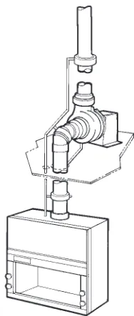
Service Fixtures
Utility services include connections to gases, air, water and vacuum (Figure 12). If service fixtures are required, they should be installed to allow the con-nection of service supply lines either on the hood itself or the work surface supporting the hood. All service valves should be accessible for maintenance and should be corrosion resistant if located inside the hood. The plumbing tubing should be of the proper material to satisfy local code requirements. For example, some states require gas service connec-tions to be made with black iron pipe or tin-lined copper tubing. For safety and convenience, all service fixtures should be remotely controlled from outside the hood and clearly identified.
Electrical Receptacles
[image:10.504.281.398.100.188.2]If electrical receptacles are required, they are usually located on the hood exterior, away from the corro-sive effects of the fumes inside the hood structure (Figure 13). Provisions should be made so that all
electrical wiring is isolated and physically separated from vapors handled within the hood.
Lighting
Light fixtures come in either vapor-proof or explo-sion-proof styles (Figure 14). Vapor-proof light fix-tures are usually fluorescent, installed outside the hood liner and protected from the hood interior by a transparent, impact-resistant shield. Access for replacing or cleaning should be from the exterior, whenever possible. Explosion-proof lights are nor-mally incandescent bulbs protected by a specially reinforced fixture mounted in the hood.
Americans with Disabilities Act Requirements
[image:10.504.326.388.351.472.2]Employers, except very small businesses, must com-ply with the Americans with Disabilities Act (ADA), a statute prohibiting discrimination against disabled individuals in employment. Fume hoods and acces-sories are available with features that meet the requirements of the ADA. Switches, controls and written instructions should be located where they can be seen and reached by a seated person. Hoods should have appropriate work surface height and clearance underneath to allow a person in a wheel-chair to work comfortably. Audible alarms must have an intensity and frequency that can attract the atten-tion of individuals who have partial hearing loss. Figure 12. Components of a gas service fixture
Figure 13. Duplex electrical receptacle
Figure 14. Explosion-proof light fixture protects incandescent bulb with globe and sealed housing
Tin-lined copper tubing
[image:10.504.47.238.510.602.2]Performance and Installation
Considerations
Face Velocity and Containment Issues
The laboratory’s degree of exposure to toxic contam-inants is an important consideration when selecting a fume hood. The concentration of contaminants in the actual breathing zone of the operator should be kept as low as possible. Two fume hood issues that impact the concentration of contaminants are face velocity and containment.
Regulatory compliance agencies and other advi-sory groups have established guidelines relating to the exposure limits of various chemical reagents. These exposure limits are identified as American Conference of Governmental Industrial Hygienists (ACGIH) Threshold Limit Values (TLV) or Occupational Safety and Health Administration (OSHA) Permissible Exposure Limits (PEL). Threshold Limit Values refer to airborne concentra-tions of substances and represent condiconcentra-tions under which it is believed workers may be repeatedly
exposed day after day without adverse effect. Until recently, general thinking was that the lower the TLV number, the higher the face velocity required to ensure adequate protection for the oper-ator. Face velocity is still regarded as an important parameter for assessing a hood’s performance. However, present views focus on containment rather than face velocity alone. Higher velocity is not neces-sarily better. A face velocity that is too high can cause turbulence within the hood and actually decrease the hood’s ability to contain contaminants. Consult the latest edition of Industrial Ventilation, A Manual of
Recommended Practice, published by the ACGIH for
their guidelines on fume hood face velocities. Factors that affect the performance level of the laboratory hood that are not easily monitored by simple measurement of face velocity include: 1) type and location of air supply; 2) location of laboratory hood in relationship to the laboratory itself; 3) air disturbances caused by overhead air diffusers, heat registers, fans, open windows or doors or personnel movement; 4) hood sash configurations; 5) location of the worker in relation to the hood; 6) location and types of emission sources; 7) apparatus loaded or stored in the hood; 8) use of apparatus such as machine tools, grinders or centrifuges that generate aerosols and/or high velocity particles; and 9) ther-mal drafts due to extreme temperature conditions.
Because of these external demands, the American Society of Heating, Refrigerating and Air-Condition-ing Engineers (ASHRAE) Standard 110-95 was developed to demonstrate the laboratory hood’s ability to contain and exhaust contaminants released inside the hood.
ASHRAE Standard 110-95 is a performance test, not a performance specification. It describes how to evaluate a hood’s performance, but it does not specify the performance level required. It remains the responsibility of the user, industrial hygienist, safety officer or applications engineer to specify the perfor-mance level requirement for a laboratory’s individual situations.
ASHRAE Standard 110-95 gives a relative and quantitative determination of the efficiency of the hood to capture contaminants under a set of strict conditions. This test is used to evaluate hoods, both in the manufacturer’s facility (as manufactured, AM), and on site (as installed, AI, or as used, AU).
Briefly, ASHRAE Standard 110-95 is a three part test. First, the average face velocity is calculated. The sash opening is divided into one-foot squares. Velocity readings are taken in each grid area and averaged (Figure 15).
Protector®Plus Laboratory Hood with low-mounted switches
Second, the hood is tested for its ability to contain fumes. Titanium tetrachloride, which emits a white smoke, is released at prescribed locations within the hood’s interior and work surface. Smoke is observed and any air movement toward the face of the hood and any areas of no air movement are noted. Titanium tetrachloride is also passed under the air foil and any smoke flowing out the front is noted.
In the final part of the test, a tracer gas is released at an established rate and at various positions within the hood. The gas is monitored in the breathing zone of a mannequin placed at various positions in front of the hood. Based on the average exposure in the breathing zone, a performance rating is determined. The complete standard is available from ASHRAE.
It is recommended that laboratory hoods be tested at the time of installation to verify the AM test results. Initial testing provides a baseline for future maintenance checks. Hood performance should be evaluated routinely to ensure safe operation.
Proper Techniques for Hood Use
Containment and efficient removal of fumes are enhanced when the operator follows proper hood procedures. Apparatus should be placed at least six inches inside the hood. Large apparatus that can obstruct airflow should be elevated on blocks to allow fumes to pass under them. The hood should not be used as a storage cabinet; equipment in the hood should be kept to a minimum so airflow is not compromised. Finally, the sash should be closed as much as possible when work is being performed inside the hood. The Industrial Ventilation Manual may be referenced for a complete list of recommen-dations for proper operator techniques.
Ventilation System Components and Accessories
The laboratory hood is just one component of a complete fume ventilation system. At the same time a hood is selected, a blower, ductwork, base cabinet and work surface must also be selected (Figure 16). Air supply must be determined as well. A laboratory fume hood may, as appropriate, also include an air-flow monitor, filtration system and fire extinguisher.
Remote Blowers
Of all the additional components needed, the blower is the most crucial to the performance of the hood. Fume hood installations utilizing remote blowers are the most common type. Since the entire duct length is under negative air pressure, any leakage in the duct is drawn in and contained rather than pushed out into the building environment. The exhaust blower is positioned in a penthouse or on the building’s exteri-or, usually on the roof, where noise is less noticeable. By creating suction within the ductwork, blowers draw air from the laboratory room, through the hood and out the duct system.
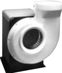
[image:12.504.64.215.66.259.2] [image:12.504.274.456.173.475.2]Centrifugal type blowers are popular because they are more efficient and less noisy than others. Belt-driven impellers have greater flexibility than direct-drive impellers because the belt can be Figure 15. One-foot square grid pattern for velocity readings
Figure 16. Typical components of a hood ventilation system Zero Pressure Weathercap
Blower Transition Adapter
Manual Duct Damper
Fume Hood
Work Surface
Base Cabinet Flexible Duct Connection Thermoplastic
Duct
Female Duct Coupling
adjusted to vary the air volume. Blower components are constructed from a variety of materials. To resist corrosion from chemical fumes, impellers may be made of various types of steel or plastic. For weather-proofing when roof-mounted, blowers have protec-tive housings. Blowers used to exhaust potentially flammable materials should be explosion-proof, meaning the blowers’ components are designed to contain a spark and prevent the escape of flame or heat that could ignite a flammable atmosphere.
In addition to centrifugal blowers, other exhaust devices are available including air ejectors (Figure 17). An air ejector creates suction by venturi method to draw fumes through the ductwork. Air ejectors are suitable for use with highly corrosive fumes, such as perchloric acid, because the blower wheel never comes into contact with the fumes. Air ejectors are considerably more expensive and noisier than cen-trifugal type blowers.
Blower Sizing
To provide the optimum face velocity and air volume for the laboratory hood, the blower must be sized properly. Although horsepower and revolutions per minute (RPM) are important blower specifications, blower selection should be based on the air volume the hood will exhaust and the total static pressure loss of the entire system.
Air Volume
The air volume passing through the hood is gener-ally equal to the area of the sash opening multiplied by the average velocity desired. For example, if 100 feet per minute (fpm) is required and the hood has a sash opening of 7.5 square feet, then the hood’s air volume is 750 (7.5 x 100) cubic feet per minute (CFM).
Static Pressure Loss
At any given exhaust volume, the hood has a unique static pressure loss usually expressed in inches of water. The manufacturer can provide this static pres-sure loss information. In addition, the ductwork components (duct, elbows, reducers, weathercaps) and filters in the system have static pressure losses based on the volume of air passing through them, which is often expressed as equivalent resistance in feet of straight duct. To determine the total pressure loss in the ductwork, the equivalent resistance in feet of straight duct for all the components in the system is totaled. This total equivalent feet provides a method to calculate the static pressure loss at specific air volumes. The static pressure loss of the ductwork is added to the static pressure losses of the hood and any filters for the total static pressure loss of the system.
Integral Motor/Blowers
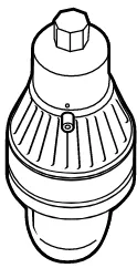
Some fume hoods are available with motors and blowers built directly into the hood superstructure (Figure 18). These hoods are relatively easy and inex-pensive to install. However, a built-in blower should not be used for corrosive or highly toxic applications since it causes positive air pressure in the duct sys-tem, and any leaks could push contaminants out of the ductwork. This type of hood may be more noisy since the blower is closer to the user. Long duct runs, too, may prohibit its use since these blowers are sized to fit a narrow range of static pressure requirements. The manufacturer can provide duct length parame-ters for its laboratory hoods with built-in blowers. Labconco Fiberglass Blower, a centrifugal blower with
[image:13.504.87.194.62.186.2]belt-driven impeller
Figure 17. Air ejector installed with washdown system
Stack Wash Line
Optional Damper
Optional Wash Ring
Airflow Monitor
American National Standards Institute (ANSI) Standard Z9.5 requires the use of an airflow monitor, a device that gives warning (by a visible or audible signal, or both) when the airflow through the hood has deviated from a predetermined level. When mounted in an easily accessible area, monitors may have locking devices to prevent tampering by unau-thorized personnel. Other monitors include a remote alarm signal and/or automatic auxiliary-air/exhaust blower interlock which shuts off the auxiliary-air blower should the exhaust blower fail.
Exhaust Air Treatment
Depending on the hazard level associated with the laboratory operation, and the degree of pollution abatement required, treatment for the hood’s efflu-ents may be necessary. Treatment methods include
filtering, wet scrubbing and incineration, each effective for a specific range of materials. No univer-sal treatment exists.
Dry media filters (95% efficient by ASHRAE Standard 52-68 Test Method) or HEPA filters (99.97% efficient by DOP Test Method) may be required to meet specified design criteria (Figure 19). The filter assembly may include a prefilter for cap-turing coarse particles and a filter enclosure arranged for easy access. For removing gaseous organic com-pounds, activated charcoal filters are often satisfacto-ry. Many filters are not suitable for collecting radioisotopes. Consult a reputable filter manufac-turer for specific recommendations.
For convenient handling, replacement and disposal with minimum hazard to personnel, the filter should be: (1) located outside the laboratory area unless it is an integral part of the hood; (2) ahead of the exhaust blower; and (3) installed in space that provides free, unobstructed access. The filter should be located on the suction side of the exhaust blower and as close to the laboratory as possible to minimize the length of contaminated ductwork. Some installations will require shut-off dampers and hardware for filter decontamination in the ductwork. A damper is often added to filtered hoods to balance airflow because HEPA filters vary and change in airflow resistance as they load during use.
The filter housing should provide easy transfer of the contaminated filter to a disposal site. Depending on the nature of the work, the filter may need to be treated as hazardous waste. Local codes should be consulted for regulations on disposal.
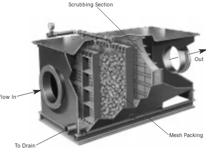
[image:14.504.62.218.60.251.2] [image:14.504.48.242.432.614.2]Fume scrubbers are another type of device placed in the hood or in the fume duct system to remove particulates and soluble contaminants from exhaust air. Scrubbers use water or chemical sprays to remove particulates and to neutralize and dilute acids or alkaline materials (Figure 20). Scrubbers may have a filtering system to trap particulates. Figure 18. Hood with integral motor/blower
Figure 19. HEPA filter with housing designed for in-line connection to duct system
Ductwork
Ductwork includes fume pipe, male and female couplings, elbows, reducers and exhaust discharge stacks (weathercaps). Round diameter duct made of rigid materials offers the least static resistance. Like the liner material of a laboratory hood, duct material must be resistant to the fumes exhausted through it. Ductwork made of unplasticized polyvinyl chloride (PVC) is a popular choice because it is rigid, highly resistant to both acid and solvent vapors and, because it is extruded, comes in round diameters. Stainless steel and coated steel are used when very high temperatures are anticipated and because they offer fire protection. Fiberglass provides high struc-tural strength and corrosion resistance. Local codes should be consulted for duct material recom-mendations.
ventilated only if the hood is operating continuously. Chemical storage cabinets that need ventilation can be more effectively and economically ventilated with a separate, continuously-running exhaust system than by connecting them to a laboratory hood.
Work Surfaces
[image:15.504.19.226.57.206.2]The work surface, the slab or platform that supports the hood, should be made of a chemical-resistant and heat-resistant material compatible with the application. Some are designed with a dished surface to contain spills. Popular choices include molded epoxy resins, aluminum silicate, natural stone and other composite materials. Specialty hoods, such as those for perchloric acid and radioisotope applica-tions, have built-in work surfaces. The smooth one-piece design of built-in work surfaces improves and simplifies decontamination procedures. Built-in work surfaces require a structural support under-neath them.
Figure 20. Swirlaway®Fume Scrubber utilizing water spray
Protector®Acid Storage Cabinet with SpillStopper™
Work Surface
Round PVC pipe with female coupling
90-Degree PVC elbow
Base Cabinets
Most laboratory hoods are designed to rest on a bench-high base stand or cabinet with a work sur-face. Existing casework may be used as long as it pro-vides adequate depth and height for the structural support of the hood. Base stands that allow the users to be in the sitting position may be preferable for persons with limited mobility. Specialty base cabinets are available that store acids or solvents. If base cabi-nets are vented into a laboratory hood, they will be Flow In
To Drain
Scrubbing Section
Mesh Packing Out
By-Pass Blocks
As described earlier, by-pass hoods are designed so that as the sash is closed, the constant volume of air entering the hood is redistributed to by-pass open-ings which helps reduce the potential for extremely high face velocities. By-pass blocks partially obstruct the by-pass openings above the sash of the hood to reduce the air volume demanded. When used with a sash stop, a by-pass block can conserve conditioned room air.
Sash Stops
A sash stop is a device to restrict the sash opening height during normal working conditions. Maintaining the sash in a lowered position can reduce the exhaust volume demand so hoods with sash stops may utilize small blowers. This practice generally requires a by-pass block.
Sash Position Alarms
To encourage users to keep the sash lowered, a sash position alarm provides audible and/or visual warn-ing when the sash is raised above a designated level. Sash position alarms may be used alone or in con-junction with a sash stop.
Fire Extinguishers
Hoods can be scenes of fires due to the nature of some applications. Some hood manufacturers offer automatic fire extinguishers that mount inside or adjacent to the hood and discharge at pre-determined temperature set points, providing around-the-clock protection.
Renovating Existing Laboratory Fume
Hoods and Ductwork
While the changes may be subtle to the untrained eye, modern laboratory fume hoods are much more efficient at capturing fumes than many of the hoods built in the 60’s and 70’s. Hoods can now be tested according to ASHRAE 110-1995 and their perfor-mance levels compared to others. The addition of air foils at the front lip of the bench and other aerody-namic components have reduced turbulence and loss of containment from the hood.
It is usually not possible to retrofit older hoods to bring their performance up to today’s standards. However, the addition of necessary components to an older hood is an expensive custom exercise that requires exacting engineering and design knowledge.
When replacing or adding to existing ductwork, extreme caution is required to avoid exposure to contaminants. In particular, ductwork exposed to perchloric acid can be potentially explosive and should only be removed by personnel experienced in handling these substances. Anytime an exhaust system is modified, testing should be done to ensure that the changes have not affected fume hood performance.
Planning Laboratory Space
Whether adding one hood to an existing laboratory or installing hundreds in a new facility, planning is crucial. Because each hood affects the room’s ventila-tion and traffic flow, the whole picture must be con-sidered including the laboratory space, the building’s ventilation and the hood’s location in the room. The first and most imperative step taken should be to consult a qualified laboratory ventilation expert who can provide helpful advice through the planning, selection and installation phases.
Laboratory Layout
In determining the amount of space necessary for the laboratory, a layout of all essential laboratory equipment should be made. The hood should always be located so that exit from the laboratory will not be impeded in the event of a fire or explosion within the hood structure itself. The hood should also be located away from high pedestrian traffic lanes in the laboratory to avoid disruptions to the airflow enter-ing the hood. Cross currents from room ventilation should also be avoided, as they distort the flow of air essential to the safe operation of the fume hood. If ventilation components are in place, an attempt should be made to position the hood out of their influence (Figure 21). Some redirecting or blocking may be necessary. Hoods should not be installed in a location where it is likely to be affected by another piece of equipment, such as a biological safety cabi-net or another fume hood. When possible, the hood side wall should be at least one foot away from the room wall to allow access to service connections. Snuffer™Fire Extinguisher mounts inside the
[image:16.504.274.460.574.681.2]hood superstructure
Figure 21. Laboratory layout showing hood located away from exits and potential airflow disruptions
Casework Alternate
Hood Location
Block register opening facing hood
Air Supply
Register Air SupplyRegister
Hood
Sufficient Room Air
A fume hood should not be installed without first considering whether the laboratory’s supply air sys-tem will be able to replace all of the air exhausted. For proper hood operation and user safety, there must be sufficient room air available for exhausting to achieve the face velocity required. The National Fire Prevention Association (NFPA) Code 45 calls for replacing the laboratory with slightly less than the amount of air exhausted from the hood. This nega-tive pressurization causes a slight inflow of air into the laboratory from corridors and non-laboratory spaces that helps to keep contaminants from spread-ing throughout the buildspread-ing.
In general laboratory situations, “Prudent Practices for Handling Hazardous Chemicals in Laboratories” states that the room air should be totally replaced at least 4-12 times an hour. Special laboratory functions may require an even greater number of air exchanges to ensure personnel safety. Open windows are not a substitute for a properly designed make-up air system.
“Air changes per hour” or “air changes per minute,” however, are not a basis for ventilation cri-teria when environmental control of hazards, heat and/or odors is required. The required ventilation depends on the problem, not on the size of the room in which it occurs. The laboratory’s safety officer should establish design criteria for room air changes.
Energy Conservation
For every 300 cubic feet per minute of air exhausted, approximately one ton of refrigeration is required. With energy resources becoming more scarce and more expensive every day, conservation is a high pri-ority. Several methods to reduce the energy exhaust-ed by a hood have been developexhaust-ed.
Variable air volume hoods use dampers or vari-able speed blowers to decrease the volume of air exhausted when demand is low, such as at night. Reduced air volume hoods function with by-pass blocks and sash stops which reduce the maximum sash opening areas thus lessening the air volume requirements. Auxiliary-air hoods can reduce the hood’s demand for room air by replacing a portion of the conditioned air exhausted with supplemental air from outside the laboratory. Proper user training can enhance energy conservation as well.
Noise Control
The standard action level for noise in the work place sets permissible noise exposure at 85 dBA for eight hours. Following certain guidelines ensures that the noise in the laboratory created by a laboratory hood ventilation system never approaches the permissible noise level. The hood should be aerodynamically
designed with smooth edges, rounded corners and a belled entry at the duct collar to reduce the noise created by air passing through it. Properly sized duct components installed with the minimum number of angles reduces air movement noise. Installing the blower outside the laboratory, preferably on the roof, keeps the single largest source of noise away from the work place. Sturdily-constructed hoods and flexible duct connections minimize vibration noise.
Conclusion
The purpose of the preceding discussion was to pro-vide important factors to consider when selecting a laboratory hood ventilation system. Space limitations kept discussions brief. The General References that follow offer sources of in depth information on the factors presented in this booklet. Labconco can also provide technical assistance and help with laboratory planning. Our Ventilation Ventures Team (VVT) comprised of engineers and product specialists com-bine their expertise to help solve end users’ labora-tory ventilation problems. You can reach us at 800-821-5525 or 816-333-8811.
Laboratory Ventilation Standards
Federal Register 29 CFR Part 1910Non-mandatory recommendations from “Prudent Practices”
•
Fume hoods should have a continuous monitoring device•
Face velocities should be between 60-100 linear feet per minute (lfpm)•
Average 2.5 linear feet of hood space per person Occupational Health and SafetyU.S. Department of Labor 200 Constitution Avenue N.W. Washington, DC 20210 (202) 523-8151
Industrial Ventilation-ACGIH
•
Fume hood face velocities between 60-100 lfpm•
Maximum of 125 lfpm for radioisotope hoods•
Duct velocities of 1000-2000 fpm for vapors, gasses and smoke•
Stack discharge height 1.3-2.0 x building height•
Well designed fume hood containment loss <0.10 ppmIndustrial Ventilation, A Manual of Recommended Practice
22nd Edition, 1995
American Conference of Governmental Industrial Hygienists
ASHRAE 110-1995 Method of Testing Performance of Fume Hoods
Evaluates fume hood’s containment characteristics
•
Three part test: Smoke generation, Face velocity profile, Tracer gas release @ 4 liters per minute•
Rated As Manufactured (AM) and As Installed (AI) American Society of Heating, Refrigerating, andAir-Conditioning Engineers 1791 Tullie Circle N.E.
Atlanta, GA 30329 (404) 636-8400
ANSI Z9.5-1992 Laboratory Standard
Covers entire laboratory ventilation system
•
Vertical stack discharge @ 2000-3000 fpm•
New and remodeled hoods shall have a monitoring device•
Ductless hoods should only be used with non-haz-ardous materialsAmerican Industrial Hygiene Association 2700 Prosperity Avenue, Suite 250 Fairfax, VA 22031
(703) 849-8888
SEFA 1-1992
•
Fume hood face velocities based on toxicity levels of chemicalsClass A –125 to 150 fpm Class B–80 to 100 fpm Class C–75 to 80 fpm
•
Test method—face velocity profile and smoke generationScientific Equipment & Furniture Association 1028 Duchess Drive
McLean, VA 22102 (703) 790-8661 FAX (703) 790-9573
NFPA 45 - 1996 Fire Protection for Laboratories Using Chemicals
•
Laboratory hoods should not be relied on for explosion protection•
Exhaust air from fume hoods should not be recirculated•
Services should be external to the hood•
Canopy hoods only for non-hazardous applications•
Materials of construction should have flame spread of 25 or lessNFPA 30 -1993 Flammable and Combustible Liquids Code
•
Approved cabinets may be metal or wood•
Vent location on cabinets are required•
Venting of cabinets not a requirement National Fire Protection Association 1 Batterymarch ParkP.O. Box 9101
Quincy, MA 02269-9101 (800) 344-3555
General References
American Conference of Governmental Industrial Hygienists.
Industrial Ventilation, A Manual of Recommended Practice, 22th
Edition. Cincinnati, OH: 1995.
American Conference of Governmental Industrial Hygienists.
1991-1992 Threshold Limit Values for Chemical Substances and Physical Agents and Biological Exposure Indices. Cincinnati, OH: 1991.
ASHRAE Standards Committee. ASHRAE Standard. Atlanta: ASHRAE Publications Sales Department, 1995.
British Standards Institution. Laboratory Fume Cupboards. Parts 1, 2 and 3. London: 1990.
Department of Labor, Occupational Safety and Health Administration. 29 CFR Part 1910, Occupational Exposures to
Hazardous Chemicals in Laboratories; Final Rule. Vol. 55, No. 21.
Washington, D. C.: 1990.
DiBerardinis, L. et al. Guides for Laboratory Design, Health and Safety
Considerations. Wiley & Sons, 1987.
McDermott, Henry. Handbook of Ventilation for Contaminant Control,
2nd Edition. Butterworth Publishers, 1985.
Miller, Brinton M. et al. Laboratory Safety: Principles and Practices. American Society for Microbiology, Washington, D.C.: 1986.
Minimum Acceptable Face Velocities of Laboratory Fume Hoods and Guidelines for their Classification. Oak Ridge National Laboratory
#ORNL/TM 7400.
National Fire Protection Association. NFPA 45 Fire Protection for
Laboratories Using Chemicals. Quincy, MA, 1996.
NIH Guidelines for the Laboratory Use of Chemical Carcinogens.
NIH Publication No. 81-2385.
Rayburn, Stephen R. The Foundations of Laboratory Safety, A Guide
for the Biomedical Laboratory. Springer-Verlag, New York: 1990.
Sax, N. Irving and Lewis, Jr., Richard J. Rapid Guide to Hazardous
Chemicals in the Workplace. Van Nostrand Reinhold, 1987.
Schilt, Alfred A. Perchloric Acid and Perchlorates. The G. Frederick Smith Chemical Company, Columbus, OH: 1979.
Scientific Equipment & Furniture Association. SEFA Laboratory Fume
Hoods. Standard 1991.
Glossary
access opening That part of the fume hood through which work is
performed; entrance or sash opening.
activated charcoal filter A filter containing activated carbon media
designed to trap gaseous organic compounds by adsorption or absorption.
air ejector An air moving device which creates suction by venturi method
to draw fumes through the ductwork to the atmosphere. An alternative to a blower.
airflow monitor A detection device mounted on a fume hood which
alerts the operator to low airflow levels.
air foil Curved or angular member(s) at the fume hood entrance which
helps to control the pattern of air moving into the hood.
air volume Quantity of air normally expressed in cubic feet per minute
(CFM).
auxiliary-air Supply or supplemental air delivered to a fume hood to
reduce room air consumption; make-up air or add-air.
auxiliary-air hood A fume hood designed with a means of providing
supplemental air for the hood exhaust thereby reducing room air consumption.
baffle Panel located across the fume hood interior back which controls the
pattern of air moving into and through the fume hood.
biological safety cabinet Safety enclosure with HEPA filter(s) which
provides containment for airborne particulates such as infectious or carcinogenic agents; laminar flow biohazard hood. This enclosure is not a fume hood.
blower Air moving device, sometimes called a fan, consisting of a motor,
impeller and housing.
by-pass Compensating opening that maintains a relatively constant
volume exhaust through a fume hood, regardless of sash position, and that functions to limit the maximum face velocity as the sash is closed.
by-pass block Device which partially obstructs the by-pass opening above
the sash of a by-pass hood, reducing the air volume demand.
by-pass hood A fume hood designed with openings above and below
the sash to minimize fluctuations in face velocity as the sash is raised or lowered.
California hood A fume hood used to house distillation apparatus that
can provide visibility from front and back or all sides, with horizontal sliding access doors along the length of the assembly. The hood, when connected to an exhaust system, contains and carries away fumes gen-erated within the enclosure when doors are closed or when the access opening is limited.
canopy hood Suspended ventilating device used to exhaust heat, steam
and odors. This device is not a fume hood.
capture velocity The air velocity at the hood face necessary to overcome
opposing air currents, and to contain contaminated air within the fume hood.
clean bench An enclosure which directs HEPA-filtered air vertically or
horizontally over the work area providing product protection. This enclosure is not a fume hood and does not provide personnel protection.
conventional hood A basic fume hood with an interior baffle and
movable front sash.
cross draft A flow of air that blows into or across the face of the hood. damper Device installed in a duct to control airflow volume. dead air space Area inside a fume hood with no air movement. distillation hood A fume hood that provides a work surface
approxi-mately 18 inches above the room floor, to accommodate tall apparatus.
downdraft hood An enclosure designed for applications involving heavier
than air materials in which the blower is mounted below the work surface so that air is pulled down through a mesh surface before being exhausted to the outside. This enclosure is not a fume hood.
duct Round, square or rectangular tube or pipe used to enclose
moving air.
ductless carbon-filtered enclosure An enclosure which houses filters to
trap certain chemical fumes and vapors.
ductwork Duct and all the components necessary to connect pieces of
duct together including adapters, reducers, elbows and couplings.
effluent Waste material (fumes, particles, smoke) discharged to the
atmosphere.
explosion-proof Description for hoods or other devices with specially
designed electrical components that totally contain and isolate electrical sparks from fume exposure so they cannot generate a fire or explosion.
face Front or access opening of a fume hood.
face velocity Speed of air moving into a fume hood entrance or access
opening, usually expressed in feet per minute (fpm).
fan Air moving device, usually called a blower, consisting of a motor,
impeller and housing.
fume scrubber An exhaust treatment device which uses water or chemical
sprays to remove particles and to neutralize and dilute acids.
glove box A leak-tight chamber with glove ports and gloves for handling
materials inside, a viewing window for observing, and a transfer chamber or door for loading and unloading. This enclosure is not a fume hood.
HEPA filter High-efficiency particulate air filter. A disposable
extended-pleated dry-type filter with a minimum particle removal efficiency of 99.9% for thermally generated monodisperse DOP smoke particles with a diameter of 0.3 micron.
laminar flow cabinet Name applied to clean bench or biological safety
enclosure that uses a smooth directional flow of air to capture and carry away airborne particles.
liner Interior lining used for side, back and top enclosure panels, exhaust
plenum and baffle system of a fume hood.
make-up air Supply or supplemental air delivered to a fume hood to
reduce room air consumption; auxiliary-air or add-air.
manometer Device used to measure air pressure differential, usually
calibrated in inches of water.
modified by-pass system A method used by some variable air volume
hoods whereby when the sash is lowered to a certain level, air volume is no longer reduced and some air volume enters through by-pass openings to maintain a volume great enough to adequately dilute and transport fumes.
negative air pressure Air pressure lower than ambient. positive air pressure Air pressure higher than ambient.
reverse airflow Air movement from inside the hood toward the face of
the hood.
reduced air volume (RAV) hood A fume hood which uses a sash stop and
by-pass block to reduce the air volume demand so that a smaller blower can be utilized and energy savings realized.
room air That portion of the exhaust air taken from the room. sash Movable tansparent panel set in a fume hood entrance. sash stop Device which restricts the height the sash can be raised. service fixture Item of laboratory plumbing mounted on or fastened to
laboratory furniture or fume hood intended to control the supply of piped gases and liquids for laboratory use.
static pressure Air pressure in a fume hood or duct, usually expressed in
inches of water.
static pressure loss Measurement of resistance created when air moves
through a duct or hood, usually expressed in inches of water.
threshold limit value-time weighted average (TLV-TWA) The
time-weighted average concentration for a normal 8-hour workday or 40-hour work week, to which nearly all workers may be repeatedly exposed, day after day, without adverse affect as established by OSHA.
transport velocity Minimum speed of air required to support and carry
particles in an air stream.
variable air volume (VAV) hood A fume hood which alters the exhaust
volume based on demand, while maintaining a face velocity within a preset range.
velocity pressure Pressure caused by moving air in a fume hood or duct,
usually expressed in inches of water.
walk-in hood A floor-mounted, full-height fume hood, designed to
accommodate tall apparatus and to permit roll-in of instruments and equipment.
weathercap Device used at the top of an exhaust stack to prevent rain
from entering the stack end.
work surface The slab or platform which supports the hood and rests
Labconco Corporation
8811 Prospect Avenue Kansas City, MO 64132-2696 U.S.A.
800-821-5525 / 816-333-8811 Fax: 816-363-0130 E-mail: [email protected] Home Page: www.labconco.com