The impact of temperature on wave interaction with damage in
composite structures
R.K. Apalowoa, D. Chronopoulosa, M. Ichchoub, Y. Essac, F. Martin De La Escalerac
aInstitute for Aerospace Technology&The Composites Research Group, The University of Nottingham, NG7 2RD,
UK
bEcole Centrale de Lyon, 36 Avenue Guy de Collongue, 69130 Ecully, France cAernnova Engineering Solutions Iberica, Madrid, Spain
Abstract
The increased use of composite materials in modern aerospace and automotive structures, and
the broad range of launch vehicles’ operating temperature imply a great temperature range for
which the structures has to be frequently and thoroughly inspected. A Thermal Mechanical
Anal-ysis (TMA) is used to experimentally measure the temperature dependent mechanical properties
of a composite layered panel in the range of -100◦C to 150◦C. A hybrid wave finite element
(WFE)/finite element (FE) computational scheme is developed to calculate the temperature
de-pendent wave propagation and interaction properties of a system of two structural waveguides
connected through a coupling joint. Calculations are made using the measured thermomechanical
properties. Temperature dependent wave propagation constants of each structural waveguide are
obtained by the WFE approach and then coupled to the fully FE described coupling joint, on which
damage is modelled, in order to calculate the scattering magnitudes of the waves interaction with
damage across the coupling joint. The significance of the panel’s glass transition range on the
measured and calculated properties is emphasised. Numerical results are presented as illustration
of the work.
Keywords: Temperature dependent mechanical characteristics, Wave propagation properties,
Damage detection, Wave finite element, Composite structure
Contents
1 Introduction 2
2 Measurement of Temperature Dependent Mechanical characteristics 5
3 Calculation of Temperature Dependent Wave characteristics 6
3.1 Wave Propagation Modelling . . . 6
3.2 Wave Dissipation Modelling . . . 9
3.3 Calculation of Wave Scattering Coefficients . . . 10
4 Numerical Results 12
4.1 Temperature Dependent Wave Properties . . . 12
4.2 Temperature Dependent Wave Scattering Coefficients . . . 13
5 Concluding remarks 15
1. Introduction
Composite structures are being increasingly used in many industrial fields, such as aerospace
and military, due to their versatile physical and mechanical properties. However, aerospace and
automotive structures operate within varying temperature range, which is typically from -100◦C
to +200◦C for launch vehicles and from -60◦C to +50◦C for aircraft and automobile structures.
Despite their versatility, composite structures may exhibit a great variety of structural failure
modes for which they must be thoroughly inspected in order to ensure continuous usage and
struc-tural integrity. These modes which include delamination, notch, fibre breakage, matrix crack and
debonding, occur mainly as a result of loads during service and inaccuracies during manufacturing.
Aeronautics industries spend approximately 27% of an average modern aircraft’s lifecycle cost on
offline inspection and repair of the structural failures [1]. Therefore, the non-destructive damage
detection and evaluation is of paramount importance for monitoring the condition and residual life
estimation of in-service aerospace structures. Of particular interest is thermal dependent damage
Thermomechanical behaviour of laminated structures have been conducted on various topics.
In [2], the elastodynamic response of a polymeric laminate subjected to a discrete range of
tem-peratures at a constant relative humidity is studied, with damping and dynamic longitudinal elastic
modulus presented as a function of temperature dependent. In [3, 4], the temperature dependent
elastic constant and dynamic shear properties of an epoxy resin and its carbon fibre-reinforced
composite are presented. More recently, the effect of high temperature on the thermomechanical
response of various composite structures, such as multi-layered plates and shells [5], glass epoxy
composites [6, 7] and carbon fibre epoxy composites [8], [9], has been extensively assessed.
More-over, temperature dependent wave based detection of structural damage has been an extensive field
of study over the recent years. In [10, 11] baseline subtraction approach is used to predict
temper-ature effect on guided wave signal and to optimally enhance the long term stability of the signal.
The approach is extended in [12, 13] to reduce the number of baseline measurements to be used.
Pitch-catch approach is used to numerically predict and experimentally measure the effect of low
[14] as well as moderately [15] and extremely [16] elevated temperature on the lamb wave
re-sponse in sandwich panels and aluminium plates respectively. This is extended in [17] to cover
a wider range of temperature in a large frequency range. Semi analytical finite element (SAFE)
model is developed in [18] to predict guided wave response under varying temperature in plate.
More recently co-integration technique is developed to control the effect of varying temperature
in damage detection of structure based on spectral lines analysis [19, 20], wavelet decomposition
[21] and direct Lamb wave responses [22]. To the best of the authors’ knowledge, FE based
com-putational scheme is quite limited in this field of research and the investigation of thermal effect
on wave interaction in complex and arbitrarily layered composite structures is almost in-existent
in the open literature.
Wave based damage detection methods are based on calculating the reflection and transmission
coefficients at the point of inhomogeneity or structural discontinuity. The inhomogeneity can be in
the form of joints such as point and finite joint [23], beam connection [24], plate and stiffened rib
connection [25], angled joint [26], curved junction [27], T-junction [28] and L-junction [29, 30],
or in form of defects, such as crack [31] and delamination [32] along the structure. It has been
forms of inhomogeneity. Calculations of the scattering coefficients and vibrational response have
been exhibited using various numerical methods, such as spectral element method [33], boundary
element method [34], finite element method [35], decomposition method [36] and probabilistic
optimisation [37]. Other methods include combined Wave and Finite Element (WFE) method
[30, 38], finite and spectral element method [39] and finite and strip element method [40]. Among
these numerical methods, the WFE method [30, 38, 41, 42] is one of the most efficient
computa-tional methods suitable for predicting the vibracomputa-tional response and wave interaction with damage
in various types of structures. The method has recently found applications in predicting the
vi-broacoustic and dynamic performance of composite panels and shells [43–45], with pressurized
[46] and complex periodic structures [47–49] having been investigated. The variability of acoustic
transmission through layered structures [50], as well as wave steering effects in anisotropic
com-posites [51] have been modelled through the same methodology. Therefore, application of this
method to predict thermal effect on wave interaction in composite structure will be a significant
contribution to the field of non-destructive damage detection using wave based models.
The main novelty of this article is to exhibit the effect of temperature on the wave properties of
a composite layered panel and consider the interaction of the waves with damage as a function of
temperature. The temperature dependent mechanical properties of a carbon epoxy facesheet
mate-rial and a honeycomb core matemate-rial, constituting the layered panel, are experimentally calculated
using a Thermal Mechanical Analysis. A structural system consisting of two healthy waveguides
connected by a coupling joint, on which damage is described, is considered. A wave finite element
approach is used to calculate the wave propagation constants of each waveguide. These are then
coupled to standard finite element model of the coupling joint, in order to calculate waves-damage
interaction scattering coefficients. All calculations are temperature dependent.
The paper is organised as follows. Section 2 presents the experimental measurement of the
temperature dependent mechanical properties of the facesheet and core materials. Section 3
presents the calculations of temperature dependent wave properties and dispersion
characteris-tics, as well as the computation of temperature dependent wave scattering properties. Numerical
results are presented in Section 4 together with a discussion of the findings. Finally, Section 5
2. Measurement of Temperature Dependent Mechanical characteristics
A Thermal Mechanical Analysis (TMA) device is used to measure the temperature dependent
sandwich panel comprising of a carbon epoxy facesheet and a quasi-isotropic honeycomb core,
which absorbs and adheres to the resin in which the facesheet is impregnated. In the
polymerisa-tion process, the resin serves as the facesheet matrix as well as the binding agent. The nominal
mechanical characteristics of the composite panel’s constituents at 20◦Care shown in Table 1.
[Table 1 about here.]
[Figure 1 about here.]
Measurements are made at a temperature range of -5◦C to 150◦C and then extrapolated for the
results of temperatures up to -100◦C by assuming smooth quadratic expansion of the curves. This
extrapolation is done to capture the lower limits of the operating temperature range of the
com-posite panel as an aerospace structure. Such extrapolation is generally acceptable for comcom-posite
materials having no significant transition (such as crystallisation) in their metallography structure
at low temperature range (such as those below -5◦C). Temperature dependent Young’s modulus of
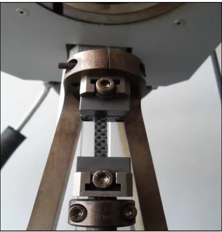
the facesheet material is measured using the TMA device, as shown by configuration in Fig. 1, by
subjecting a segment of the facesheet to an initial longitudinal traction test before imposing a 1 Hz
excitation as displacement to the segment. The corresponding material loss factor is determined
astanδ=E1/E2, whereδis the phase lag between the stress and strain, E1the loss modulus and E2
the storage modulus of the material. A reduction ratio, Rf, calculated as Rf =Ea/Enis determined
at each temperature of the measured Young’s modulus, with Ea the measured (actual) values at
respective temperature and En the nominal value as given in Table 1. This is used to calculate
the actual values of other mechanical characteristics of the material as Ea =Rf ×En at each
cor-responding temperature using the nominal value of each of the mechanical characteristics. The
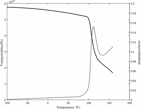
results of the experimental measurements and the corresponding material loss factor are presented
in Fig. 2. Measured elastic modulus decreases while the corresponding material loss factor
in-creases slightly with temperature until 110◦
is a drastic increase of the loss factor to the peak level at this temperature range. Beyond this
tem-perature, the elastic modulus decreases rapidly with temperature while the loss factor decreases,
then start increasing again due to the high viscosity of the resin at this temperature.
[Figure 2 about here.]
[Figure 3 about here.]
[Figure 4 about here.]
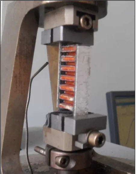
On the other hand, temperature dependent shear modulus of the honeycomb core is measured
using the TMA machine by subjecting a segment of the core to shear deformation as shown in
the configuration in Fig. 3. In order to avoid any influence of the elasticity of the facesheet on
the shear deformation of the core’s segment, a steel sheet layer is attached on it to increase its
rigidity. Similar calculations, as described in the Young’s modulus measurement, are carried out
to determine the shear modulus and the corresponding dissipation ratios of the quasi-isotropic
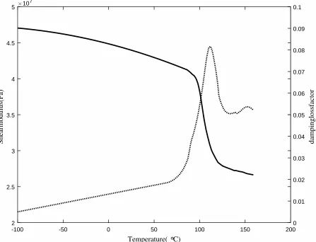
honeycomb core. The results of the temperature dependent shear modulus measurements and
corresponding dissipation ratios are shown in Fig. 4. Results measured in this case show similar
trend as in the case of the facesheet material.
3. Calculation of Temperature Dependent Wave characteristics
3.1. Wave Propagation Modelling
One dimensional elastic wave propagation alongxdirection of an arbitrarily layered sandwich
panel is considered. A segment of the periodic waveguide is meshed using a single finite element
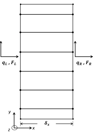
along the axis of wave propagation and an arbitrary number of elements in other directions Fig.
6. The left and right hand sides of the segment both have the same number of nodes and degrees
of freedom (DOFs) [52]. The problem can be condensed using the transfer matrix approach [53].
The temperature and frequency dependent dynamic stiffness matrix (DSM) is determined as
whereK,MandCare the stiffness, mass and damping matrices of the FE model for each
consid-ered temperatureT.
The dynamic equilibrium of the model is obtained by partitioning the DSM with respect to the
the left, right and internal DoFs of the segment as
DLL DLI DLR
DIL DII DIR
DRL DRI DRR
qL qI qR = FL FI FR (2)
[Figure 5 about here.]
whereqandFare the displacement and internal force vectors respectively. The internal force
vector responsible for transmitting the wave from one element to the other within the structure,
hence it is non-zero, even for a free wave motion where no external load is applied [52]. In the
case where no external forces are exerted on the internal nodes (FI = 0), classical condensation
techniques [54], such as the Guyan-type condensation, is applied to condense the internal DoFs
entries as given in Eq. (2). The finite element mesh of the section of the segment with the internal
nodes condensed is shown in Fig. 5.
DLL−DLID−1IIDIL DLR−DLID−1IIDIR
DRL−DRID−II1DIL DRR−DRID−II1DIR
qL qR = FL FR (3) D∗ LL D ∗ LR D∗ RL D ∗ RR qL qR = FL FR (4)
where the matrixD∗ is the reduced dynamic stiffness matrix. Therefore, the continuity condition
and equilibrium of forces equations at the interface of two consecutive periodic segmentsr and
r+1 are given as
qR(r)= qL(r+1);FR(r) =−FL(r+1) (5)
Combining Eqs. 4 and 5, gives the relation of the displacement and force vectors of the left
qR(r)
FR(r)
=
qL(r+1)
−FL(r+1)
=T
qL(r)
FL(r)
(6)
where matrixTis the transfer matrix expressed as
T= −D∗ LR
−1D∗
LL D
∗
LR
−1
−D∗RL+D∗RRD∗LR−1D∗LL −D∗RRD∗LR−1
(7)
As the wave is propagating only in the x-direction, a constant of propagation, λ, relates the
left side’s displacement and internal force of the segment to that of the right side according to the
Bloch’s theorem [55] as
λqL(r) =qR(r);−λFL(r) =FR(r) (8)
Combining Eqs.6 and 8, the free wave propagation can be defined by the eigenvalue problem
T
qL(r)
FL(r)
=λj
qL(r)
FL(r)
(9)
whose solution yields the temperature dependent constant of propagation, λj and the
wavenum-bers,kj as
kj(ω,T)= −
lnλj(ω,T)
iδx
, j=1,2, ....,2n (10)
where subscript j corresponds to wave type j and n the number of DoFs one side of the segment
andδx the length of a periodic segment.
The wave modes obtained at each frequency and temperature is post processed and partitioned
as Φ=
Φqinc Φqre f
ΦFinc ΦFre f
(11)
whereinc and re f denote the positive and negative going waves respectively. Assuming modal
qL FL
(k)
=Φ Qinc
Qre f
(k)
(12)
where Q denotes the amplitudes of the wave modes. The physical domain, where the motion
is represented in terms of displacements and nodal forces, has been transformed into the wave
domain, where the motion is described in terms of the incident and reflected wave amplitudes.
3.2. Wave Dissipation Modelling
The governing displacement relation for time harmonic wave motion, according to Bloch’s
theorem [55] can be given as
w= Wei(ωt−kx) (13)
wherewis the displacement of the wave motion,W the maximum amplitude,kthe wavenumber,
xthe axial distance travelled along the structure,tthe time andωthe wave frequency.
The dissipation ratio of the wave after travelling over a certain length along the structure can
be determined as
dr =10 logA1 A0
(14)
dris the dissipation loss of the travelling wave in decibel per unit length,A0andA1the amplitudes
at the reference points in consideration. The amplitudes of the wave, A0 and A1, at a reference
pointsx0andx1, can be expressed as
A0 =Aei(ωt−kx0);A1 =Aei(ωt−kx1) (15)
where A is the maximum amplitude of the wave. Eq. (14) can be transformed into
dr =10
lnA1
A0
ln 10 (16)
which can be combined with Eq. (15) and considering the that ω and t are constant at the two
length can then be given as
dr =10 |kim|
ln 10 (17)
where|kim|is the absolute value of the imaginary part of the wavenumber.
3.3. Calculation of Wave Scattering Coefficients
The degree of wave scattering, due to wave interaction with damage along the system, is
de-termined using the modes properties of the waves that impinges on the damage. The reflection
coefficient is the fraction of the incident wave reflected while the transmission coefficient is the
fraction of the wave transmitted beyond the damage. As the wave propagation is unidirectional
and impinging at 90o, no refraction is expected.
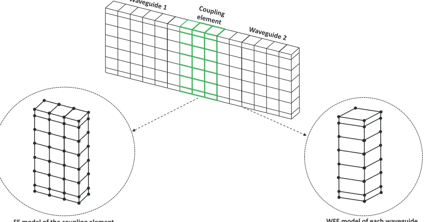
[Figure 6 about here.]
The description of the system is based on the assembly of a number of identical waveguides
connected through a joint, referred to as the coupling element/joint. A system of two coplanar
waveguides connected through a coupling joint, as shown in Fig. 6, is considered. In this
ap-proach, the connecting surfaces of the waveguides with the coupling element must have the same
mesh. The method can be extended tonnumber of waveguides [56] and to waveguides connected
at angles [30]. Waves propagate from the two healthy waveguides through the joint on which
structural damage (notch or crack) is modelled. Wave interaction coefficients are calculated by
coupling the WFE calculated wave propagation constants of the waveguides to the standard FE
model of the joint.
The coupling joint is modelled in a similar manner as described in Section 3.1, but its segment
is fully meshed (using its whole length) along the axis of wave propagation rather than using a
single element as in the case of the WFE model. Its DSM are partitioned, into corresponding
components of interface and non-interface nodes in the waveguides-coupling joint assembly, as
D11 D12
where subscript 1 corresponds to the DoFs of the interface nodes of the two waveguides with
the coupling joint, and subscript 2, the non-interface nodes. Eq. (18) can then be condensed to
determine the dynamic stiffness matrix, DC∗, of the interface nodes’ DoFs in the assembly, as
given in Eq. (15).
D∗C=D11−D12D−221D21 (19)
With the assumption of a similar mesh at the connecting interface, then the nodal displacement
and internal force vectors can be given as
qC,L
qC,R
=
q1R
q2L
;
FC,L
FC,R
=
F1R
F2L
(20)
where subscripts 1 and 2 denote the waveguides to the left and right sides of the coupling joint
respectively. The dynamic equilibrium equation of the assembly can then be given as
DC∗
q1R
q2L
=
F1R
F2L
(21)
Eq. (21) in wave domain is given as
DC∗
Φq1incQ1inc +Φq1re fQ1re f
Φq2incQ2inc +Φq2re fQ2re f =
ΦF1incQ1inc +ΦF1re fQ1re f
ΦF2incQ2inc +ΦF2re fQ2re f (22)
22 can be rearranged in terms of the amplitudes of reflected and incident waves, and simplified
as
Q1re f
Q2re f =S
Q1inc
Q2inc (23) where
S=−
ΦF1re f 0
0 ΦF2re f
−DC∗
Φq1re f 0
0 Φq2re f
−1
ΦF1inc 0
0 ΦF2inc
−DC∗
Φq1inc 0
4. Numerical Results
The application of the approach developed is applied to the layered panel for predicting its
temperature dependent wave propagation constants and wave interaction scattering coefficients
as presented in Section 3. Calculations are made over temperature range of -100◦C to 150◦C.
FE modelling is done in ANSYS 14.0. The layered panel is meshed using SOLID185 elements,
which comprises a 3D displacement fields and is defined by eight nodes having three degrees of
freedom at each node: translations in the nodal x, y, and z directions. It also possesses formulation
capability for simulating viscoelastic layered structures [57]. The temperature dependent mass and
stiffness matrices extracted from the FE solution of the modelling analysis in ANSYS are
post-processed in MATLAB to obtain the required wave properties of the model as discussed Section
3.
4.1. Temperature Dependent Wave Properties
The temperature dependent wave propagation constants of the viscoelastic layered panel is
sought as presented in Sections 3.1 and 3.2. The panel’s temperature dependent mechanical
prop-erties (elastic and shear moduli) and their respective material loss factor of the materials are
pre-sented in Figs. 2 and 4. The thickness of the core,hc, is 12.7 mm while that of the facesheet,hc, is
1.0 mm. The dimension of the panel is 1.0 mm× 1.0 mm. The finite element model of the panel
is made using eight elements to discretise each of the facesheets and five elements to discretise the
core, resulting in a total of twenty-one elements.
[Figure 7 about here.]
[Figure 8 about here.]
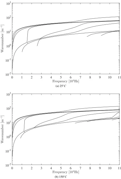
The wavenumber plots of the propagating waves along the panel are shown in Figs. 7 and 8.
Four propagating waves, in-plane and out-of-plane flexural waves as well as torsional and axial
waves, exist below the frequency of 10 kHz. The cut-on frequencies and number of waves within
the considered frequency range depend on temperature as shown in Fig. 7. While at 25◦
C, there are
75kHz and 90kHz as shown in Fig. 7a, there are eleven waves at 150◦
C, with cut-ons occurring
at about 10kHz, 12kHz, 22kHz, 68kHz, 78kHz, 102kHz and 109kHz as shown in Fig. 7b. Some
of the waves exhibit modeshape change. This is observed as the point of curvature along the lines
of the waves. Examples of such are the mode change of the flexural mode to axial at about 65kHz
and of the axial mode to flexural at about 18kHz as shown in Fig. 7. The effect of temperature
on the wavenumber magnitude can be analysed using the temperature dependent torsional wave
dispersion relation shown in Fig. 8. Little difference in wavenumber is observed between -100◦C
and 90◦C, whereas a significant difference of about 30% is observed between 90◦C and 110◦C, and
beyond 110◦C, the wavenumber increases at a steady rate. It is therefore evident that the panel’s
wavenumber will exhibit significant difference within and beyond the glass transition temperature
range (90◦C to 110◦C).
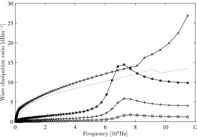
[Figure 9 about here.]
The temperature dependent wave transmission loss of the layered panel is calculated using
the approach presented in Section 3.2. The torsional wave transmission loss as a function of
temperature is presented in Fig. 9. In a similar trend to the wavenumber results, the difference in
the maximum dissipation ratio just before and after the glass transition range, is about 30% and
maximum loss ratio is obtained within the range.
4.2. Temperature Dependent Wave Scattering Coefficients
The temperature dependent waves scattering coefficients of the waves interaction with damage
along the layered panel is calculated as presented Section 3.3. Two forms of damage are studied,
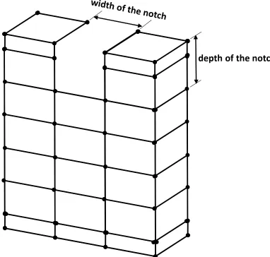
notch and crack. Notch is modelled by deleting elements along the line of the damage, as shown
in Fig. 10. Crack is simply a notch of zero width. It is created by disconnecting the connecting
nodes along the line of the crack to indicate surface breaking due to the crack [58].
As earlier stated, a system of two waveguides connected through a coupling joint(on which the
damage is modelled) is considered. Each waveguide is a sandwich panel, comprising a honeycomb
foam core and the upper and lower carbon fibre facesheets. The thickness of the core, hc, is 10
dimension of the panel is 1.0 mm×5.0 mm. The panel is meshed using 1 mm (in each direction)
elements. Hence, each waveguide has a total of 40 elements; 10 in the upper layer, 25 in the core
and 5 in the lower layer. The coupling joint is modelled in the same manner as three segments of
each waveguide in length, as shown in Fig. 6.
[Figure 10 about here.]
In the case of notch model, notch of 1 mm width and 2 mm depth is located at 1 mm from the
left edge of the coupling joint. Similarly, a crack of 2 mm depth is modelled in the same location.
In each case of the damage models, the WFE model of each waveguide is solved, then coupled
with the solution of the FE model of the coupling element as explained in Section 3.3.
[Figure 11 about here.]
[Figure 12 about here.]
[Figure 13 about here.]
[Figure 14 about here.]
[Figure 15 about here.]
[Figure 16 about here.]
In both the crack and notch models, four classical propagating waves, which are flexural
(in-plane and out-of-(in-plane), torsional and axial waves, exist in the frequency range within 0.2kHz
and 120kHz. Results of the reflection coefficients magnitude of these waves for the crack model
are shown in Figs. 11, 12 and 13. Scattering coefficient trends of the axial and torsional waves
show more sensitivity to change in temperature at higher frequencies in the range above 60kHz,
while that of the flexural wave shows significant difference only in the range 25kHz to 85kHz but
insignificant to temperature change outside this frequency range. The effect of temperature on the
reflection coefficient below, within and after the glass transition temperature varies significantly.
the wave types with a maximum difference of about 10% per 50◦Cchange in temperature. Above
the glass transition temperature, a considerable difference is observed with respect to temperature
change with an observed difference of about 28% per 50◦Cchange in temperature. Results for the
reflection coefficients magnitude as a function of temperature for the notch model are presented in
Figs. 14, 15 and 16. Compared to the notch model results, similar trend is observed in the crack
model for the wave interaction coefficients relationship with temperature change, especially with
regards to the glass transition range. Generally, the significance of the glass transition temperature
range on the scattering properties along the panel is quite similar to that obtained for the panel’s
thermomechanical characteristics and wave propagation constants
5. Concluding remarks
The temperature dependent mechanical characteristics of a quasi-isotropic sandwich panel are
presented in this article. The panel is made of two materials, carbon epoxy facesheet, impregnated
in the resin and draped over the mould, and a quasi-isotropic honeycomb core. The
thermome-chanical characteristics of each of these materials are separately measured experimentally and it
is observed that there is a large divergence of the material loss factor, elastic and shear moduli
especially within and above the glass transition temperature of the resin. The thermomechanical
characteristics are then used to determine the temperature dependent wave propagation
proper-ties of the panel using a wave finite element approach. An idealised system of two waveguides
connected through a coupling element is considered. Two forms of damage; crack and notch are
modelled along the coupling element. The wave finite element modelling of each waveguide
seg-ment is then coupled with the full finite eleseg-ment model of the coupling eleseg-ment (joint), on which
damage is modelled, in order to calculate the temperature dependent scattering coefficients of the
waves interaction with the damage. As in the case of the experimental results for the moduli and
the material loss factor, the numerically predicted wave propagation properties and the wave
scat-tering coefficients exhibit significant difference in their results before the glass transition
tempera-ture compared to that after the glass transition temperatempera-ture. It can be concluded that temperatempera-ture,
especially at glass transition range, is a significant factor that should be taken into consideration in
References
[1] S. S. Kessler, S. M. Spearing, C. Soutis, Damage detection in composite materials using lamb wave methods,
Smart Materials and Structures 11 (2002) 269–78.
[2] C. Y. Lee, B. S. Thompson, M. V. Gandhi, Temperature-dependent dynamic mechanical properties of polymeric laminated beams, J. Eng. Mater. Technol 110 (1988) 174–9.
[3] A. J. Barker, H. Vangerko, Temperature dependent elastic constants of cfrp composites, Composites 14 (1983)
52–6.
[4] A. J. Barker, H. Vangerko, Temperature dependent dynamic shear properties of cfrp composites, Composites
14 (1983) 141–4.
[5] A. K. Noor, U. S. Burton, Computational models for high temperature multilayered composite plates and shells,
Appl Mech Rev 45 (1992) 419–46.
[6] Y. I. Dimitrienko, Thermomechanical behaviour of composite materials and structures under high temperature:
1. materials, composites, Part A. Applied Science and Manufacturing 28 (1997) 463–71.
[7] Y. I. Dimitrienko, Thermomechanical behaviour of composite materials and structures under high temperature:
2. structures, composites, Part A. Applied Science and Manufacturing 28 (1997) 453–61.
[8] G. M. McNally, M. P. McCourt, P. L. Spedding, The effect of rapid high temperature excursions on the
mois-ture absorption and dynamic mechanical properties of carbon fibre epoxy composite materials, development in
chemical engineering and mineral processing, Asia-Pacific Journal of Chemical Engineering 12 (2004) 169–78.
[9] O. Putkis, R. P. Dalton, A. J. Croxford, The influence of temperature variations on ultrasonic guided waves in
anisotropic cfrp plates, Ultrasonic 60 (2015) 109–16.
[10] G. Konstantinidis, P. D. Wilcox, B. W. Drinkwater, The long-term stability of guided wave structural health
monitoring systems. review of progress in quantitative nondestructive evaluation, American Institute of Physics
25B (2006) 1702–9.
[11] G. Konstantinidis, B. W. Drinkwater, P. D. Wilcox, The temperature stability of guided wave structural health
monitoring systems, Smart Materials and Structures 15 (2006) 967–76.
[12] T. Clarke, P. Cawley, P. D. Wilcox, A. J. Croxford, Evaluation of the damage detection capability of a
sparse-array guided-wave shm system applied to a complex structure under varying thermal conditions, IEEE
Transac-tions on Ultrasonics Ferroelectrics and Frequency Control 56 (2009) 2666–78.
[13] T. Clarke, P. D. Wilcox, P. Cawley, Guided wave health monitoring of complex structures by sparse array
systems: influence of temperature changes on performance, Journal of Sound and Vibration 329 (2010) 2306–
22.
[14] E. Blaise, F. K. Chang, Built-in diagnostics for debonding in sandwich structures under extreme temperatures, in Proceedings of the Third International Workshop on Structural Health Monitoring, Stanford University (2001)
[15] B. C. Lee, G. Manson, W. J. Staszewski, Environmental effects on lamb wave responses from piezoceramic
sensors, Material Science Forum 440–441 (2003) 195–202.
[16] M. J. Schulz, M. J. Sundaresan, J. Mcmichael, D. Clayton, R. Sadler, B. Nagel, Piezoelectric materials at
elevated temperature, Journal of Intelligent Material Systems and Structures 14 (2003) 693–705.
[17] F. L. di Scalea, S. Salamone, Temperature effects in ultrasonic lamb wave structural health monitoring systems,
Journal of Acoustical Society of America 124 (2008) 161–74.
[18] A. Marzani, S. Salamone, Numerical prediction and experimental verification of temperature effect on plate
waves generated and received by piezoceramic sensors, Mechanical Systems and Signal Processing 30 (2012) 204–17.
[19] E. J. Cross, K. Worden, Approaches to nonlinear cointegration with a view towards applications in shm, Journal
of Physics: Conference Series 305 (2011) 12069–78.
[20] E. J. Cross, K. Worden, Q. Chen, Cointegration: a novel approach for the removal of environmental trends in
structural health monitoring data, Proceedings of the Royal Society of London 467 (2011) 2712–32.
[21] K. Worden, E. J. Cross, A. Kyprianou, Cointegration and nonstationarity in the context of multiresolution
analysis, Journal of Physics: Conference Series 305 (2011) 12004–15.
[22] P. B. Dao, W. J. Staszewski, Cointegration approach for temperature effect compensation in lamb-wave-based
damage detection, Smart Materials and Structures 22 (2013).
[23] R. S. Langley, P. J. Shorter, The wave transmission coefficients and coupling loss factors of point connected structures, Journal of the Acoustical Society of America 113 (2003) 1947–64.
[24] R. S. Langley, K. H. Heron, Elastic wave transmission through plate/beam junctions, Journal of Sound and
Vibration 143 (1990) 241–53.
[25] I. Bosman, T. Nightingale, modelling vibrational energy transmission at bolted junctions between a plate and a
stiffening rib, Journal of the Acoustical Society of America 109 (2001) 999–1010.
[26] S. A. F. M. Ishak, J. M. Horner, S. J. Walsh, modelling and experimentation of vibration transmission through an
angled joint, 42nd International Conference and Exposition on Noise Control Engineering, Innsbruck, Austria
(2013).
[27] S. K. Lee, B. R. Mace, B. M. J., Wave propagation, reflection and transmission in curved beams, Journal of Sound and Vibration 306 (2007) 636â ˘A ¸S–656.
[28] M. Rucka, W. Witkowski, J. Chroscielewski, K. Wilde, Damage detection of a t-shaped panel by wave
propa-gation analysis in the plane stress, Archives of Civil Engineering 58 (2012) 3–24.
[29] M. Rucka, Experimental and numerical study on damage detection in an l-joint using guided wave propagation,
Journal of Sound and Vibration 329 (2010) 1760–79.
[30] J. M. Renno, B. R. Mace, Calculation of reflection and transmission coefficients of joints using a hybrid
[31] S. P. Shone, B. R. Mace, W. T. P., Estimation of reflection and transmission coefficients using the spectral
element method: application to crack modelling in beams, in: International Conference on Noise and Vibration
Engineering, Leuven 2004, ISMA, 2004, pp. 187â ˘A ¸S–200.
[32] C. H. Wang, L. R. F. Rose, Wave reflection and transmission in beams containing delamination and
inhomo-geneity, Journal of Sound and Vibration 264 (2003) 851â ˘A ¸S–872.
[33] S. P. Shone, B. R. Mace, T. P. Waters, Reflection and transmission coefficients using the spectral element method:
Application to crack modelling in beams., Proceedings of Institute of acoustics Spring Conference, Institute of
Sound and Vibration Research, Southampton, UK (2004).
[34] X. G. Zhao, J. L. Rose, Boundary element modelling for defect characterization potential in a wave guide,
International Journal of Solids and Structures 40 (2003) 2645–58.
[35] M. Veidt, C. T. Ng, Influence of stacking sequence on scattering characteristics of the fundamental
anti-symmetric lamb wave at through holes in composite laminates, The Journal of the Acoustical Society of America
129 (2011) 1280–7.
[36] M. Castaings, E. Le Clezio, B. Hosten, Modal decomposition method for modelling the interaction of lamb
waves with cracks, The Journal of the Acoustical Society of America 112 (2002) 2567–82.
[37] C. T. Ng, M. Veidt, H. F. Lam, Guided wave damage characterisation in beams utilising probabilistic
optimisa-tion, Engineering Structures 31 (2009) 2842–50.
[38] W. J. Zhou, M. N. Ichchou, Wave scattering by local defect in structural waveguide through wave finite element method, Structural Health Monitoring 10 (2011) 335–49.
[39] S. P. Shone, B. R. Mace, T. P. Waters, A combined finite and spectral element approach to wave scattering in a
cracked beam: modelling and validation, Key Engineering Materials (2005) 541–8.
[40] G. Liu, A combined finite element/strip element method for analyzing elastic wave scattering by cracks and
inclusions in laminates, Computational Mechanics 28 (2002) 76–82.
[41] J. M. Renno, B. R. Mace, Vibration modelling of structural networks using a hybrid finite element/wave and
finite element approach, Wave Motion 51 (2014) 566–80.
[42] E. Manconi, B. R. Mace, Modelling wave propagation in two-dimensional structures using finite element
anal-ysis, ISVR Technical Memorandum 318 (2008) 884–902.
[43] D. Chronopoulos, B. Troclet, M. Ichchou, J. P. Laine, A unified approach for the broadband vibroacoustic
response of composite shells, Composites Part B: Engineering 43 (2012) 1837–46.
[44] D. Chronopoulos, B. Troclet, O. Bareille, M. Ichchou, Modeling the response of composite panels by a dynamic
stiffness approach, Composite Structures 96 (2013) 111–20.
[45] R. K. Apalowo, D. Chronopoulos, V. Thierry, Thermal effect on wave interaction in composite structures, 19th
International Conference on Aerospace, Mechanical, Automotive and Materials Engineering, London, United
[46] R. K. Apalowo, D. Chronopoulos, V. Thierry, Wave interaction with defects in pressurized composite
struc-tures, 19th International Conference on Aerospace, Mechanical, Automotive and Materials Engineering,
Lon-don, United Kingdom (2017).
[47] D. Chronopoulos, M. Collet, M. Ichchou, Damping enhancement of composite panels by inclusion of shunted
piezoelectric patches: A wave-based modelling approach, Materials 8 (2015) 815–28.
[48] D. Chronopoulos, I. Antoniadis, M. Collet, M. Ichchou, Enhancement of wave damping within metamaterials
having embedded negative stiffness inclusions, Wave Motion 58 (2015) 165–79.
[49] D. Chronopoulos, I. Antoniadis, T. Ampatzidis, Enhanced acoustic insulation properties of composite metama-terials having embedded negative stiffness inclusions, Extreme Mechanics Letters (2016).
[50] D. Chronopoulos, Design optimization of composite structures operating in acoustic environments, Journal of
Sound and Vibration 355 (2015) 322–44.
[51] D. Chronopoulos, Wave steering effects in anisotropic composite structures: Direct calculation of the energy
skew angle through a finite element scheme, Ultrasonics 73 (2017) 43–8.
[52] E. Manconi, B. R. Mace, Modelling wave propagation in two-dimensional structures using a wave/finite element
technique, ISVR Technical Memorandum (2007).
[53] B. R. Mace, D. Duhamel, M. J. Brennan, L. Hinke, Finite element prediction of wave motion in structural
waveguides, The Journal of the Acoustical Society of America 117 (2005) 2835–43.
[54] W. X. Zhong, F. W. Williams, A. Y. T. Leung, Sympletic analysis for periodical electro-magnetic waveguides, Journal of Sound and Vibration 267 (2003) 227–44.
[55] F. Bloch, Über die quantenmechanik der elektronen in kristallgittern, Zeitschrift für physik 52 (1929) 555–600.
[56] J. M. Mencik, M. N. Ichchou, Multi-mode propagation and diffusion in structures through finite elements,
European Journal of Mechanics-A/Solids 24 (2005) 877–98.
[57] ANSYS 14.0 User’s Help, 2014.
[58] M. J. S. Lowe, C. P., J. Y. Kao, O. Diligent, The low frequency reflection characteristics of the fundamental
antisymmetric lamb wave a0 from a rectangular notch in a plate, The Journal of the Acoustical Society of
List of Figures
1 Configuration of a segment of the facesheet traction test in the TMA device . . . 21 2 Experimentally measured temperature dependent elastic modulus (-) and material
loss factor (· · ·) for the facesheet material . . . 22
3 Configuration of a segment of the core shear deformation in the TMA device . . 23 4 Experimentally measured temperature dependent shear modulus (-) and material
loss factor (· · ·) for the honeycomb core material . . . 24
5 Finite element mesh of the section of the waveguide’s segment . . . 25 6 Caption of a system of two coplanar waveguides connected through a coupling
joint/element, the WFE model of each waveguide and standard FE model of the joint 26 7 Dispersion relations for waves in the composite panel at 25◦
C and 150◦C . . . . 27
8 Dispersion relations for torsional waves in the composite panel at -100◦C(o), 25◦C
(+), 90◦C (*), 110◦C(x) and 150◦C(· · ·) . . . . 28
9 Predicted temperature dependent dissipation ratio of the layered panel for flexural wave at -100◦C(o), 25◦C (+), 90◦C(*), 110◦C(x) and 150◦C(· · ·) . . . . 29
10 FE mesh of the coupling element showing region of the notch . . . 30 11 The temperature dependent reflection coefficient magnitude of the flexural wave
from cracked joint of the panel at -100◦C (o), 25◦C (+), 90◦C (*), 110◦C (x) and
150◦C(· · ·) . . . . 31
12 The temperature dependent reflection coefficient magnitude of the torsional wave from cracked joint of the panel at -100◦C (o), 25◦C (+), 90◦C (*), 110◦C (x) and
150◦C(· · ·) . . . . 32
13 The temperature dependent reflection coefficient magnitude of the axial wave from cracked joint of the panel at -100◦C(o), 25◦C(+), 90◦C(*), 110◦C(x) and 150◦C
(· · ·) . . . 33
14 The temperature dependent reflection coefficient magnitude of the flexural wave from notched joint of the panel at -100◦C (o), 25◦C(+), 90◦C(*), 110◦C (x) and
150◦C(· · ·) . . . . 34
15 The temperature dependent reflection coefficient magnitude of the torsional wave from notched joint of the panel at -100◦C (o), 25◦C(+), 90◦C(*), 110◦C (x) and
150◦C(· · ·) . . . . 35
16 The temperature dependent reflection coefficient magnitude of the axial wave from notched joint of the panel at -100◦C(o), 25◦C(+), 90◦C(*), 110◦C(x) and 150◦C
Temperature (°C)
-100 -50 0 50 100 150 200
Young's modulus (Pa)
×1010
0 1 2 3 4 5 6
damping loss factor
[image:22.595.74.525.229.579.2]0 0.02 0.04 0.06 0.08 0.1 0.12 0.14 0.16 0.18 0.2
Temperature (°C)
-100 -50 0 50 100 150 200
Shear modulus (Pa)
×107
2 2.5 3 3.5 4 4.5 5
damping loss factor
[image:24.595.78.525.233.575.2]0 0.01 0.02 0.03 0.04 0.05 0.06 0.07 0.08 0.09 0.1
LJ
dž
nj
ࢾ
࢞
[image:25.595.105.487.124.667.2]
ࡸ
͕ࡲ
ࡸ
ࡾ
͕
ࡲ
ࡾ
FE model of the coupling element WFE model of each waveguide
Frequency [104Hz]
0 1 2 3 4 5 6 7 8 9 10 11
W
av
en
u
m
b
er
[m
−
1 ]
10-2 10-1 100 101 102 103
(a) 25◦C
Frequency [104Hz]
0 1 2 3 4 5 6 7 8 9 10 11
W
av
en
u
m
b
er
[m
−
1 ]
10-2 10-1 100 101 102 103
[image:27.595.98.495.117.702.2](b) 150◦C
Frequency [104Hz]
0 2 4 6 8 10 12
W
av
en
u
m
b
er
[m
−
1 ]
[image:28.595.101.492.255.555.2]0 200 400 600 800 1000 1200 1400
Figure 8: Dispersion relations for torsional waves in the composite panel at -100◦C(o), 25◦C(+), 90◦C(*), 110◦C
Frequency [104Hz]
0 2 4 6 8 10 12
W
av
e
d
is
si
p
at
io
n
ra
ti
o
[d
B
m
−
1 ]
[image:29.595.101.493.268.541.2]0 5 10 15 20 25 30
Figure 9: Predicted temperature dependent dissipation ratio of the layered panel for flexural wave at -100◦C(o), 25◦C
ĚĞƉƚŚŽĨƚŚĞŶŽƚĐŚ
Frequency [104Hz]
0 2 4 6 8 10 12
Magnitude
[image:31.595.106.495.274.540.2]0 0.1 0.2 0.3 0.4 0.5
Frequency [104Hz]
0 2 4 6 8 10 12
Magnitude
[image:32.595.102.496.263.538.2]0 0.1 0.2 0.3 0.4 0.5 0.6
Frequency [104Hz]
0 2 4 6 8 10 12
Magnitude
[image:33.595.102.496.262.537.2]0 0.05 0.1 0.15 0.2
Frequency [104Hz]
0 2 4 6 8 10 12
Magnitude
[image:34.595.101.495.266.540.2]0 0.1 0.2 0.3 0.4 0.5 0.6
Frequency [104Hz]
0 2 4 6 8 10 12
Magnitude
[image:35.595.101.496.261.541.2]0 0.1 0.2 0.3 0.4 0.5 0.6
Frequency [104Hz]
0 2 4 6 8 10 12
Magnitude
[image:36.595.101.496.270.539.2]0 0.05 0.1 0.15 0.2 0.25 0.3 0.35
List of Tables
1 Nominal mechanical properties of the composite panel’s constituents at 20◦
Table 1: Nominal mechanical properties of the composite panel’s constituents at 20◦C
Carbon Epoxy Honeycomb foam
E =54 GPa Ex = 85 MPa
ρ=1410 kg/m3 Ey =85 MPa
ν=0.09 ρ=48 kg/m3