Structural Optimisation of Random Discontinuous Fibre Composites:
Part 2 - Case study
C.C. Qian, L.T. Harper*, T.A. Turner, N.A. Warrior
Division of Materials, Mechanics and Structures, Faculty of Engineering,
University of Nottingham, NG7 2RD, United Kingdom
* Corresponding author ([email protected])
Abstract
This is the second paper in a two part series presenting the development of a stiffness optimisation algorithm to intelligently optimise the fibre architecture of discontinuous fibre composites. A Multi-Criteria Decision Making (MCDM) strategy is used to select parameters associated with the fibre architecture, to produce components that satisfy stiffness, cost and mass criteria.
The model has been successfully demonstrated using an automotive spare wheel well geometry, which shows that a highly optimised discontinuous fibre composite solution can compete against a continuous fabric counterpart in terms of specific stiffness, whilst presenting an opportunity for significant cost reduction. This could potentially lead to the application of composite materials into new areas where cost has previously been prohibitive.
Keywords
1 Introduction
There has been an increasing trend in using discontinuous fibre composites for automotive applications, due to their low dependency on expensive intermediate processes (weaving, pre-impregnating etc.) [1-4]. Directed Fibre Preforming (DFP) is an automated, discontinuous fibre process for producing preforms for resin transfer moulding. The resulting material potentially offers greater design freedom compared with more conventional ply-based materials, as the process enables local control over the fibre volume fraction and thickness within the part. However, due to the lack of suitable design and optimisation tools, these benefits cannot be fully exploited, as DFP structures are currently designed like metallic parts, assuming homogeneous and isotropic material properties.
Traditional optimisation routines are primarily concerned with structural issues, such as the overall mass and stiffness of the component. Whilst stiffness is one of the most significant drivers in
structural optimisation, quite often the design is assessed against multiple criteria, of which some are non-structural. Therefore, a robust design tool for discontinuous fibre structures requires additional objectives to be considered, such as material cost, component mass and manufacturing cycle time, to ensure a more realistic outcome. However, adopting multiple objectives can often lead to numerous solutions, making the overall choice more complex. For example, using inexpensive, low stiffness fibres and compromising on component mass is a possibility for achieving the same target stiffness as using more expensive fibre tows with higher specific properties. These design problems are typically solved using either multi-objective optimisation approaches [5-7], or multi-criterion material selection approaches [8-10], or a combination of structural optimisation and material selection [11-14].
first paper focused on maximising the stiffness of discontinuous fibre composite structures, whereas the current paper aims to also minimise component mass and/or cost.
Although other examples of integrating structural optimisation with material selection can be found in the literature, these studies tend to be limited to sandwich panels, where the optimum core material is determined using a material selection method and the stiffness of the structure is subsequently optimised [11, 12]. Other studies in the literature are concerned with selecting the best reinforcement type for composite components, where structural optimisation is performed for every candidate material. Therefore the material selection step is not generally integrated within the structural optimisation procedure [12, 14] and neither approach has been used for optimising discontinuous fibres. In both cases there are a very limited number of candidate materials to choose from, where each material is easily identifiable by a different weave pattern or areal density for example. For DFP, certain material parameters can be varied on a continuous scale, e.g. fibre length and areal mass, generating many more material scenarios. The novelty of the current work is to demonstrate how conventional material selection tools can be used with much larger material databases, integrating material selection into the stiffness optimisation procedure as part of designing optimum
discontinuous fibre components for structural applications.
The algorithm developed in Part 1 locally varied the thickness and areal mass distribution for a discontinuous fibre composite component, to maximise the stiffness of the component under the constraints of constant volume and material cost. Whilst the model proposed in [15] is not capable of directly solving multi-objective problems, it is possible to manually reduce the target mass and cost prior to starting the optimisation process – as they are assumed to remain constant throughout. The challenge is to ensure that this manual reduction of mass and cost has minimum impact on the structural stiffness.
designer as in Part 1. An additional step will be performed to determine the initial (un-optimised) fibre architecture, providing a series of structural optimisation solutions derived at different mass and cost levels. A Multi-Criteria Decision Making (MCDM) strategy [16] is used to rank candidate materials according to different weightings. An automotive demonstrator component has been specifically selected to demonstrate how the model can be successfully used to optimise the fibre architecture of discontinuous fibre components. The aim of this study is to demonstrate that a highly optimised discontinuous fibre composite solution can compete against a continuous fabric counterpart in terms of specific stiffness, whilst presenting an opportunity for significant cost reduction.
2 Decision Making Criterion
Discontinuous fibre composites are very versatile and their mechanical properties span a wide range [17-19] . Consequently, there are many more parameters associated with their definition compared with continuous fibre composites. These include different tow sizes; fibre lengths, local volume fractions and orientation distributions, which create a large possibility of material scenarios. This makes material selection difficult, as different materials can often be used to achieve the same mechanical performance, albeit for different cost levels.
Multiple selection criteria are considered in the current study, which can be grouped into three main categories: stiffness, mass and cost. Material selection is performed in this paper by assigning percentage weights to the three main criteria, and these in turn are made up of sub-criteria.
The stiffness criterion is divided into three sub-criteria: tensile stiffness, bending stiffness and stiffness retention. The tensile and bending stiffnesses can be calculated as
Equation 1
Equation 2 tensile stiffness =ܧݐ
whereE, tdenote the Young’s modulus and section thickness.
The segmentation step is known to introduce a reduction in stiffness compared with the Initial Optimum model. The case study in Part 1[15] demonstrated that this reduction can change by up to 30% by simply increasing the critical length-scale from 30mm to 50mm. This reduction in stiffness must be compensated for by increasing the part thickness or fibre volume fraction, or using more expensive fibre with higher specific properties. This highlights the importance of taking the stiffness reduction into account and therefore a stiffness retention sub-criterion is introduced into the current model; defined as the ratio between the stiffness of the segmented model and that of the Initial Optimum.
According to [15] the critical length-scale is chosen to be four times the fibre length in the
segmentation step, to ensure a suitable RVE size is used to achieve representative in-plane stiffnesses [20, 21]. Therefore, stiffness retention is expected to be lower for 50mm fibre lengths than for 25mm fibre lengths because the critical length-scale for 50mm fibre is twice of that of 25mm fibre. An arbitrary stiffness retention value of 75% is assumed for the 25mm fibre length and 50% for the 50mm fibre length. It should be noted that the critical RVE size for discontinuous fibre composites might be affected by other factors such as fibre tow size and volume fraction, but the influence of these factors is not yet well established. Further studies will enable these factors to be incorporated into the stiffness retention sub criterion. A ratio of 1:2:1 has been assigned to the tensile stiffness, bending stiffness and stiffness retention criteria respectively, placing more emphasis on the bending stiffness due to the nature of the loads on the model.
There is no sub-criterion for the mass. The cost criterion however, consists of two elements; the cost of raw materials and a cycle time dependent manufacturing cost. The manufacturing cost is a function of the volume of fibre, as the cycle time is dependent on the total amount of fibre sprayed. A ratio of 5:2 has been adopted for the cost sub-criteria in this work, which is an arbitrary value for
An MCDM strategy has been adopted in the current work to select the most competitive solutions from a large material database containing 385 entries, taken from the literature [22, 23].The Weighted Sum Model is the most well-known and simplest MCDM strategy, where the weight of each criteria is defined by the user [24]. For every alternative solution, a score is obtained for each criteria and the optimum solution is determined from the sum of the weighted score. The Weighted Sum Model does not utilise normalised data, therefore it only works when all criteria are measured using the same unit. The Weighted Product Model [25] is an improvement of the Weighted Sum Model which is suitable for dimensionless analysis, regardless of the quantities measured and the units. The problem with both the Weighted Sum and Weighted Product models is that they require all criteria to be monotonically increasing or decreasing, which restricts their implementation in many cases.
The Technique for Order of Preference by Similarity to Ideal Solution (TOPSIS) [26, 27] is an alternative MCDM that uses weights to estimate the relative importance of each criterion, but criteria can be either increasing or decreasing. TOPSIS analysis requires a normalised decision matrix to be constructed for the current problem. Assuming there arenentries from the material database to compare, the un-normalised decision matrix can be written as:
ܥଵ ݐ݁݊ݏ݈݅݁ ݏݐ݂݂݅݊݁ݏݏ ܥଶ ܾ݁݊݀݅݊݃ ݏݐ݂݂݅݊݁ݏݏ ܥଷ ݏݐ݂݂݅݊݁ݏݏ ݎ݁ݐ݁݊ݐ݅݊ ܥସ ݉ ܽݐ݁ݎ݈݅ܽ ܿݏݐ ܥହ ܿݕ݈ܿ݁ ݐ݅݉ ݁ ܥ ݉ ܽݏݏ
ܧ݊ݐݎݕ1 ܥଵଵ ܥଵଶ ܥଵଷ ܥଵସ ܥଵହ ܥଵ ܧ݊ݐݎݕ2 ܥଶଵ ܥଶଶ ܥଶଷ ܥଶସ ܥଶହ ܥଶ
⋮ ⋮ ⋮ ⋮ ⋮ ⋮ ⋮
ܧ݊ݐݎݕ݊ ܥଵ ܥଶ ܥଷ ܥସ ܥହ ܥ
Equation 3
The normalised data are calculated as:
ܿ=ݓ×ܥ/ ൫ܥ൯ଶ
ୀଵ
൩ ݂ݎ݅= 1,2, … ,6ܽ݊݀ ݆= 1,2, … ,݊ Equation 4
Equation 5
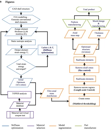
Two artificial solutions are hypothesised; the ideal solution containing the best attributes for all three criterions, and the negative solution containing the worst attributes. TOPSIS searches for the option which is the closest to the ideal solution and furthest from the negative ideal solution. A detailed derivation of the TOPSIS analysis can be found in [26, 27]. The TOPSIS analysis determines the most appropriate fibre architecture to suit all of the design requirements, and then stiffness optimisation is performed based on the selected fibre architecture using method proposed in the first part [15]. A flowchart of the optimisation process is provided in Figure 1.
3 Candidate materials
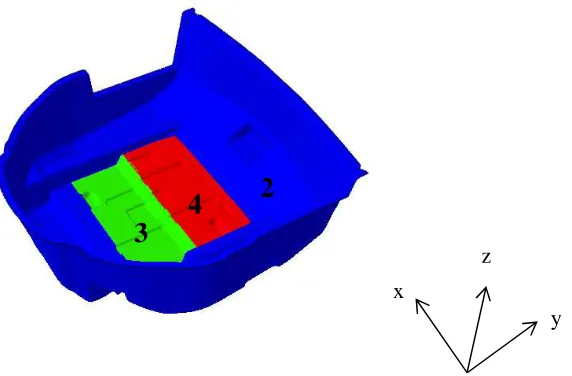
The demonstrator component (Figure 2) forms an element of the rear trunk (boot) floor structure for a large sedan (saloon) vehicle. Its secondary function is to house a spare wheel and a pair of 12V batteries, so it needs to be sufficiently stiff to avoid noise, vibration and harshness issues within the passenger cell.
The production component comprises an inner and outer skin with local areas of foam core to create a sandwich construction. The layup has been simplified for the purpose of this study into a monolithic component (ignoring cores) and is presented in Figure 2. A single ply of 650gsm 2×2 twill weave carbon fabric is sandwiched about 3 plies of 600gsm 3×1.
A replacement for the glass/carbon woven composite has been proposed using an all-carbon fibre layup consisting of 650gsm 2×2 twill weave carbon fibre plies. The ply count has been manually optimised (as shown in Figure 3) to provide a comparable structural stiffness to the glass/carbon hybrid, whilst minimising the mass and cost of the part by locally adjusting the number of plies.
A series of optimised discontinuous fibre replacements have been designed using the modified
structural optimisation algorithm, to understand if DFP can compete against continuous fibre solutions ݓ݅
6
݅=0
in terms of specific stiffness, but offer a significant cost reduction. The material cost (per m2) for DFP
is potentially 50% lower than a textile solution because no intermediate processing is required and there is little fibre wastage [28]. The process is also fully automated, which eliminates all touch labour to create further cost savings. DFP fibre architectures selected in this paper are based on tow sizes of 3K, 6K, 12K and 24K, at fibre lengths of 25mm and 50mm. Smaller tow sizes (3-6K) are typically preferred for higher performance applications where the higher material costs can be justified. (The cost of 3K fibre is typically three times the cost of 24K fibre [29]). The global fibre volume fraction for the un-optimised version is chosen from 25%, 30%, 35% and 40%, and the thickness varies from 2mm to 4mm in 0.2mm increments.
The current model selects the most appropriate fibre architecture according to the specified design requirements, of which the thickness and Young’s modulus are used as the starting conditions of the initial optimisation step [15]. The thickness limits for the initial optimisation step are chosen to be 0.5 and 1.5 times the initial thickness, and the modulus limits are calculated from volume fractions of 10% and 50% using the material model described in [15]. The minimum allowable thickness is limited to 1mm for all case studies, as extremely thin panels are impractical from a manufacturing perspective of view. A minimum zone size constraint of 22,500mm2is used and a critical length-scale
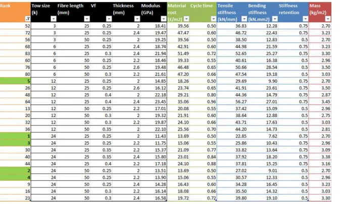
of 4 times the fibre length is adopted as discussed in [15]. A section of the material database used in this paper is presented in Table 2, which includes fibre architecture parameters, the resulting Young’s modulus, and attributes of all sub-criteria considered in the TOPSIS analysis.
mass than the glass/carbon option or a material cost higher than the all-carbon fabric solution. Therefore the TOPSIS analysis only ranks materials that would yield a composite mass of less than 4.3kg (calculated for the design in Figure 2), and a material cost of less than £63.20 (the cost for the design in Figure 3) for this case. The properties for all materials used are summarised in Table 1.
4 Results
4.1 TOPSIS sensitivity analysis
A sensitivity analysis has been performed to investigate the influence of key parameters associated with the fibre architecture (section thickness, volume fraction, tow size and fibre length) on the TOPSIS score, for the current set of ratios between the sub-criteria. This information can be used to identify the likelihood of materials being selected and can also be used to explain observed trends, for example why the recommended architectures may all share the same fibre length or tow size. The TOPSIS scores for all permutations of the selection criteria (different weightings for stiffness, cost, mass criteria) have been summed for each of the 385 fibre architectures considered. The weighting for each criterion was changed in 1% increments, with the sum of all weights remaining unity. A total of 171700 weighting permutations were analysed. Higher TOPSIS scores reflect the possibility that certain fibre architectures may be ranked as the best option more frequently than others (it does not indicate the best solution in all cases). Therefore, it is worth noting that varying each fibre architecture parameter does not necessarily affect all TOPSIS criteria at the same time: Varying fibre tow size for example, only affects the tensile stiffness, the bending stiffness and the material cost, whilst varying fibre length only affects the tensile stiffness and the bending stiffness according to the sub-criterion outlined in Section 2.
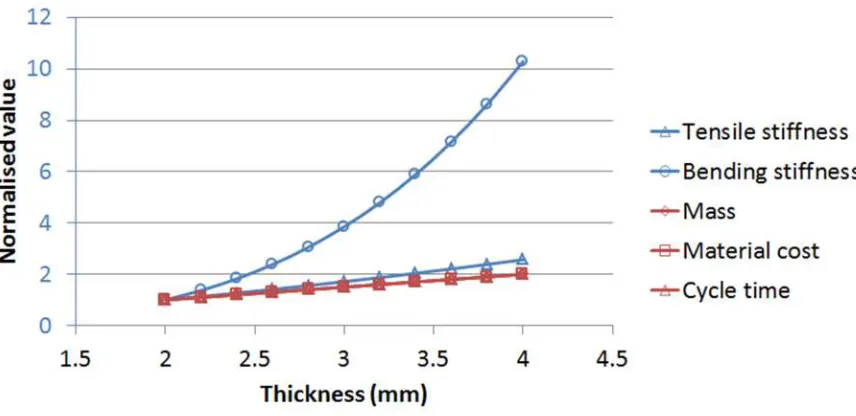
then calculating the corresponding mean value. It should be noted that in Figure 4, attentions should be paid not only to the total TOPSIS score at each data point, but also the gradient of the lines: a steeper line indicates that the fibre architecture parameter is more significant. According to Figure 4, tow size has the most significant effect on the total TOPSIS score. The TOPSIS score reflects the cost to stiffness ratio of each tow, which is the lowest for the 3K fibre and highest for the 12K and 24K fibre. Thickness is the second most significant variable, but the effects are more complicated as most sub-criteria are affected. The influence of varying thickness is demonstrated in more detail in Figure 5, where the example data is taken from all of the 3K DFP materials with a 25mm fibre length and 35% volume fraction. Figure 5 shows the relative contribution of each sub-criteria on the TOPSIS score, due to changes in section thickness. Clearly bending stiffness dominates the TOPSIS score, because of the 1:2:1 ratio between tensile stiffness, bending stiffness and the stiffness retention criteria. This explains why the TOPSIS score appears to increase for section thicknesses greater than 3.4mm in Figure 4. However for thinner panels, the TOPSIS score is dominated by the mass, material cost and cycle time (see Figure 5) and this therefore explains why the TOPSIS score is initially higher for thinner panels in Figure 4.
Both volume fraction and fibre length have a relatively minor influence on the total TOPSIS score. The influence of varying fibre volume fraction is also complicated, as stiffness, mass and material cost are all affected. All criteria are found to exhibit a linear relationship with volume fraction. The overall TOPSIS score is dominated by the negative effects of increased mass, material cost and cycle time, and therefore continuously decreases as the volume fraction increases.
Whilst this sensitivity study has considered the overall influence of each parameter, the following two case studies will discuss the suitability of using selected architectures for the demonstrator
component. The TOPSIS weights for each criterion will be selected to suit the design objective in each case.
4.2 Case 1: Optimum solution for high stiffness and lightweight
The current case study analyses all permutations of which the weighting for the stiffness criterion is ≥
40% and the weighting for the mass criterion is ≥ 40% (weighting for cost is zero in all cases),
providing a total of 21 weighting strategies to be analysed. DFP fibre architectures are ranked according to their frequency of producing a ‘top 5’ TOPSIS score.
The top 5 materials (compared in Figure 6) are dominated by 3K and 6K tow sizes because of their high specific stiffness, but the areal mass limit effectively restricts the material thickness to a maximum of 2.8mm. According to Figure 6, the TOPSIS score generally decreases as thickness increases from 2mm to 2.8mm, as the score is affected by the increase in mass more than the increase in stiffness. Therefore, restricting the areal mass means that the top 5 options all adopt the lowest thickness value (2mm). This is supported by the results presented in the Main Effects plot in Figure 4, which shows that the lower section thicknesses tend to have a higher TOPSIS score. The cost
restriction on the other hand, limits the volume fraction to a maximum of 30% for 3K DFPs, and a maximum of 35% for 6K DFP. Comparisons between Options 1 and 2 and Options 4 and 5 suggest that higher volume fractions are preferable.
4.3 Case 2: Optimum solution for low cost
This case aims to produce a high performance, lightweight part whilst targeting more aggressive cost savings. This study summarises all permutations for which the weightings for the stiffness, mass and material cost criterions are all equal to, or greater than 30% (i.e. between 30% and 40%). This produces a total of 66 weighting strategies.
The top 5 resulting materials are presented in Figure 8. They are dominated by 24K tows, except Option 4 which uses 12K. Whilst the mass limit restricts the material thickness to a maximum of 2.8mm, all 12K or 24K materials are acceptable within the cost limit. Comparisons between Options 2 and 3 and Options 1 and 5 suggest that thinner sections are more preferable for this scenario, which is the same as the observation from Case 1.
From Option 1 in Figure 8, the thickness of the model is increased to 2.3mm in order to achieve a total strain energy of 1341J and maximum deflection of 3.59mm. The optimised fibre architecture is presented in Figure 7(b). Naturally, this option has a lower stiffness and is heavier than the 3K fibre solution from Case 1. However, this 24K solution is the cheapest of all of the composite solutions under investigation, where the material cost is 69% lower than the glass/carbon benchmark. Whilst the stiffness of this optimised 24K DFP model is 2.2% lower than that of the original woven
glass/carbon hybrid design, the total mass is just 3.59kg, offering a 16% reduction compared with the glass/carbon benchmark.
4.4 Discussion of Models
This section discusses the suitability of replacing the woven glass/carbon boot floor structure with the proposed carbon fibre options. The optimised continuous carbon and the two DFP options are
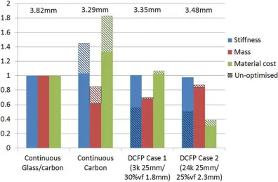
compared in Figure 9, in terms of material cost, mass and stiffness (where the stiffness is calculated from the inverse of strain energy for each model). The hatched bars in Figure 9 indicate the properties of the corresponding un-optimised models in each case.
carries an additional material cost, which is calculated to be greater than 34%. The 3K DFP material from Case 1 yields a similar specific stiffness to the all-carbon textile solution, but with material costs in line with the glass/carbon hybrid (and 25% lower than the all-carbon textile). This is achieved by more efficient use of materials, by redistributing fibres to areas experiencing higher stress. This is only possible with DFP, as it does not rely on a ply-based laminate architecture. Further cost savings are possible by adopting higher filament count tows and it has been demonstrated in Case 2 that these materials can still yield stiffness and mass levels comparable to the continuous fibre benchmark. This study has shown that it is possible to produce a structure from optimised DFP architectures, with stiffness levels approaching a continuous carbon fibre fabric, but at material cost levels typically associated with lower performance glass fibre fabrics.
It should be noted that the model currently only considers the cost of moulded materials, with no reflection of material wastage in the raw material cost. This suggests that there is potential for higher cost savings when using optimised DFP materials over carbon fibre fabric. In addition, the
manufacturing cost is expected to be much lower for the DFP option according to [28], as it requires less touch labour and the manufacturing cycle time is also much shorter. The areal mass distributions for both optimised models are relatively simple according to Figure 7, which make them suitable for high production volumes via the DFP process. The part thickness profiles are somewhat more complex, but these can be achieved through CNC machined matched tools.
5 Conclusions
The stiffness optimisation algorithm in Part 1 of this 2 part paper series [15] has been further developed to include a material selection algorithm to automatically select candidate materials, in order to meet more complex design objectives. Developments in the current paper enable the tow size and fibre length to be determined as part of the optimisation process, in the form of design variables, rather than regarding them as design constraints.
is currently manufactured from a combination of woven carbon and glass fibre composites. An alternative all-carbon fibre fabric version has been proposed as a lightweight replacement for the original design, but the material cost of continuous carbon is prohibitive. Two DFP options have been derived as a form of compromise, by optimising the discontinuous fibre architecture based on the most appropriate materials available. A DFP database was formed from experimental data which included 385 separate entries, consisting of different fibre volume fractions, tow sizes and fibre lengths etc.
6 References
[1] Bruderick, M.Applications of carbon fiber smc for the dodge viper.
[2] Driver, C.The best of both worlds: Mercedes-benz slr mclaren production in woking. 2004 20 May, 2004.
[3] Corvette sports a carbon composite bonnet.Reinforced Plastics, 2003. 47(7): p. 4. [4] Austin, M.The next frontier in carbon fiber: Forged composite. 2011.
[5] Paz, J., J. Díaz, L. Romera, and M. Costas,Crushing analysis and multi-objective crashworthiness optimization of gfrp honeycomb-filled energy absorption devices.Finite Elements in Analysis and Design, 2014. 91(0): p. 30-39.
[6] Hu, Z., P. Tan, and G. Pu,Multi-objective optimization of cassava-based fuel ethanol used as an alternative automotive fuel in guangxi, china.Applied Energy, 2006. 83(8): p. 819-840. [7] Rada-Vilela, J., M. Chica, Ó. Cordón, and S. Damas,A comparative study of multi-objective
ant colony optimization algorithms for the time and space assembly line balancing problem.
Applied Soft Computing, 2013. 13(11): p. 4370-4382.
[8] Antunes, R.A. and M.C.L. de Oliveira,Materials selection for hot stamped automotive body parts: An application of the ashby approach based on the strain hardening exponent and
stacking fault energy of materials.Materials & Design, 2014. 63(0): p. 247-256.
[9] Sakundarini, N., Z. Taha, S.H. Abdul-Rashid, and R.A.R. Ghazila,Optimal multi-material selection for lightweight design of automotive body assembly incorporating recyclability.
Materials & Design, 2013. 50(0): p. 846-857.
[10] Cui, X., H. Zhang, S. Wang, L. Zhang, and J. Ko,Design of lightweight multi-material automotive bodies using new material performance indices of thin-walled beams for the
material selection with crashworthiness consideration.Materials & Design, 2011. 32(2): p. 815-821.
[12] Ermolaeva, N.S., M.B.G. Castro, and P.V. Kandachar,Materials selection for an automotive structure by integrating structural optimization with environmental impact assessment.
Materials & Design, 2004. 25(8): p. 689-698.
[13] Ermolaeva, N.S., K.G. Kaveline, and J.L. Spoormaker,Materials selection combined with optimal structural design: Concept and some results.Materials & Design, 2002. 23(5): p. 459-470.
[14] Park, C.H., A. Saouab, J. Bréard, W.S. Han, A. Vautrin, and W.I. Lee,An integrated
optimisation for the weight, the structural performance and the cost of composite structures.
Composites Science and Technology, 2009. 69(7–8): p. 1101-1107.
[15] Qian, C.C., L.T. Harper, T.A. Turner, and N.A. Warrior,Structural optimisation of random discontinuous fibre composites: Part 1 - methodology.Composites Part A: Applied Science and Manufacturing, 2014. Under review.
[16] Figueira, J., S. Greco, and M. Ehrgott,Multiple criteria decision analysis: State of the art surveys. Vol. 78. 2005: Springer.pp
[17] BLUMENTRIT, B.F., B.T. VU, and S.L. COOPER,The mechanical properties of oriented discontinuous fiber-reinforced thermoplastics. 1. Unidirectional fiber orientation.Polymer Engineering and Science, 1974. 14: p. 633-640.
[18] FERABOLI, P., E. Peitso, F. Deleo, T. Cleveland, and P.B. Stickler,Characterization of prepreg-based discontinuous carbon fiber/epoxy systems.Composite Materials Technology, 2008: p. 289-299.
[19] MAALEJ, M.,Tensile properties of short fiber composites with fiber strength distribution.
Journal of Materials Science, 2001. 36: p. 2203-2212.
[20] Harper, L.T., C. Qian, T.A. Turner, S. Li, and N.A. Warrior,Representative volume elements for discontinuous carbon fibre composites – part 1: Boundary conditions.Composites Science and Technology, 2012. 72(2): p. 225-234.
[21] HARPER, L.T., C. QIAN, T.A. TURNER, S. LI, and N.A. WARRIOR,Representative volume elements for discontinuous carbon fibre composites – part 2: Determining the critical
[22] HARPER, L.T.,Discontinuous carbon fibre composites for automotive applications, inPhD Thesis. 2006, The University of Nottingham: Nottingham.
[23] Kirupanantham, G.,Characterisation of discontinuous carbon fibre preforms for automotive applicationsinMechanical Engineering. 2013, University of Nottingham.
[24] Fishburn, P.C.,Letter to the editor—additive utilities with incomplete product sets: Application to priorities and assignments.Operations Research, 1967. 15(3): p. 537-542. [25] Miller, D.W. and M.K. Starr,Executive decisions and operations research. 1969:
Prentice-Hall.pp
[26] Hwang, C.-L., Y.-J. Lai, and T.-Y. Liu,A new approach for multiple objective decision making.Computers & Operations Research, 1993. 20(8): p. 889-899.
[27] Yoon, K.P. and C.-L. Hwang,Multiple attribute decision making: An introduction. 1995: Sage.pp
[28] TURNER, T.A., L.T. HARPER, N.A. WARRIOR, and C.D. RUDD,Low cost carbon-fibre based automotive body panel systems - a performance and manufacturing cost comparison.
Journal of Automobile Engineering - Proceedings of the Institution of Mechanical Engineers Part D, 2008. 222(1): p. 53-64.
[29] Harper, L.T., R. Luchoo, M.D. Bond, N.A. Warrior, and A. Dodworth,Automated charge placement for structural molding compounds.SAMPE Journal, 2010. 46(5): p. 6-21. [30] Easy composites woven glass2013; Available from:
http://www.easycomposites.co.uk/products/woven-glass-fabric/woven-glass-fabric-22-twill-300g.aspx.
[31] Easy composites woven carbon. 2013; Available from:
7 Acknowledgements
8 Tables
Table 1: Material parameters for all benchmark materials and un-optimised DFPs used for the case study. (Fibre areal mass values shown in brackets). E1(E2) Nu12 G12(G13) G23 Ply thick Density Unit price
(MPa) (MPa) (MPa) (mm) Kg/m3 (£/m2)
3x1 Twill Glass Fibre (600gsm) [30] 26585 0.256 4090 3560 0.44 1946 5.12
2x2 Twill 12K Carbon Fibre (650gsm) [31] 71515 0.256 4444 3787 0.66 1524 24.40
Case 1: DFP 3K 25mm , 30% vf (967gsm) 21570 0.3 8296 8296 1.8 1377 42.72
9 Figures
[image:21.595.72.513.83.624.2]Figure 2: Left: Un-deformed shape of the spare wheel well. (0.01MPa uniform pressure applied on the pink surface) Right: Ply layup arrangement of the current composite laminate, as modelled using Abaqus/Standard composite layup. Each ply of woven fabric has been modelled as two UD plies at 0/90°. Layup asymmetry is copied from the original production part.
Figure 3: Ply configuration of the continuous carbon model. Numbers indicate the ply count of 650gsm 2×2 twill weave carbon fibre. The compass shows the material orientation where x- axis refers to 0 deg and y-axis refers to 90 deg.
x
y z
2
3
[image:22.595.96.382.376.564.2]Figure 4: Main effects plot for the total TOPSIS score of all weight permutations. The weights are changed in step size of 0.01, therefore a total of 171700 permutations are included. The TOPSIS score for a single permutation is between 0 and 1.
[image:23.595.86.514.483.691.2]Figure 6: Comparison of top five fibre architectures for Case 1: high stiffness, lightweight. Values on the top indicate the frequency that each option is ranked as one of the top five options. Vertical axis values are normalised to option 1 (3K 25mm / 30%vf 2mm).
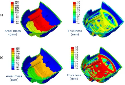
Figure 7: Case 1 (a): Optimum solution for high stiffness and lightweight - 3K, 25mm DFP. Case 2 (b): Optimum solution for low cost – 24K, 25mm DFP.
Areal mass
(gsm) Thickness(mm)
Areal mass (gsm)
Thickness (mm)
(a)
[image:24.595.66.498.387.682.2]Figure 8: Comparison of top five fibre architectures for Case 2: high stiffness, lightweight and low cost. Values on the top indicate the frequency that each option is ranked as one of the top five options. Vertical axis values are normalised to option 1 (24K 25mm / 25%vf 2mm).
Figure 9: Comparison of the carbon fibre models against the original glass/carbon design. Stiffness is compared as the inverse of total strain energy. All values are normalised to the continuous
[image:25.595.96.492.422.681.2]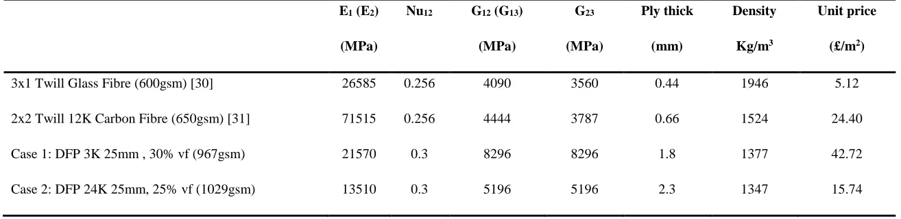
![Dimethyl 3,3′ diphenyl 2,2′ [(S) thiophene 2,5 diylbis(carbonylazanediyl)]dipropanoate](data:image/gif;base64,R0lGODlhAQABAIAAAP///wAAACH5BAEAAAAALAAAAAABAAEAAAICRAEAOw==)