1
Surface microstructuring to modify wettability for 3D
printing of nano-filled inks
Saeid Vafaei*1,2, Christopher Tuck*2, Ian Ashcroft2, Ricky Wildman3 1 Bradley University, Department of Mechanical Engineering, IL, USA.
Email: [email protected]
2 EPSRC Centre for Innovative Manufacturing in Additive Manufacturing, Additive Manufacturing and 3D Printing Research Group, Faculty of Engineering, University of
Nottingham, Nottingham, UK. Email: [email protected]
Phone: +44 (0) 115 951 3702
3 EPSRC Centre for Innovative Manufacturing in Additive Manufacturing, Department of Chemical and Environmental Engineering, University of Nottingham, Nottingham, UK. Abstract: This paper investigates the effect of surface wettability on the cross-sectional profiles of printed nanofluid inks which can have a significant role on conductivity of printed lines that are used in the production of printed electronics. Glass substrates were coated with heptadecafluorodecyltrichlorosilane, nonafluorohexyltrimethoxysilane and methyltrimethoxysilane using a dipping method to enhance the wettability of the nanofluid silver ink. Inkjet printing techniques were also applied to develop micro-structural textures on the surface of the glass substrate and thereby modify the wettability of the substrate. The glass substrate, coated with heptadecafluorodecyltrichlorosilane was micro-structured using a UV curable ink to enhance the wettability for the silver nanoparticle ink. Using inkjet printing techniques to micro-structure the substrate allows modification of the wettability of the substrate whilst simultaneously printing on to the substrate. This enables the potential of increasing the performance of such printed lines, essentially permitting additional particulate material to be deposited thus increasing conductivity. The cross-sectional profile of the printed line was predicted numerically and analytically and compared to experimental data where agreement was observed. In addition, three analytical expressions for printed lines on the substrate were developed by writing the force balance equations in the x, y and z directions on a slice of printed line between z and z+dz. Keywords: Inkjet printing, Young-Laplace equation, UV curable ink, Silver nanofluid ink, surface micro-structuring.
2
The inkjet printing of conductive nanoparticles is attractive due to potential applications in areas such as printed electronics and micro-fabrication for the electronics industry. Direct deposition of conductive nanoparticles has a significant role on cost and flexible manufacturing for the production of a wide range of electronic devices (Cummins and Desmulliez 2012). Lee et al. (2008) have discussed the advantages in inkjet printing of electronics in detail. Recent advances in Additive Manufacturing (AM), colloquially known as 3D printing, have shown increased requirements in the area of inkjet printing and importantly the inks that are being deposited. AM has been shown to produce components from single, passive, materials today, however the research agenda has moved to the production of intelligent systems, this requires the contemporaneous deposition of multiple materials (Adams et al, 2015), which lends itself to drop on demand inkjet techniques. In addition to these requirements, where active materials are to be deposited it is beneficial from both a manufacturing process and component performance point of view to enable the addition of as much active material as possible within the deposited geometry. This paper contributes to the literature by highlighting how surface control methods can be utilized to achieve this.
3
Hydrophobic substrates have previously been employed to print lines with small feature sizes (Lee et al. 2008); however, to enhance the flexibility of printing on to hydrophobic substrates,
merging (Lee et al. 2008) and bulging (Duineveld, 2003, Stringer and Derby, 2010) phenomena have to be investigated. The drop merging phenomenon arises on hydrophobic substrates when printed droplets collect together to form large individual droplets, where cohesion or intermolecular forces are dominant between two droplets. An increase in the contact angle reduces the liquid’s adherence to the solid surface and the liquid has a tendency to merge with other droplets (Lee and Cho, 2012). Substrate heating has been applied in order to increase the likelihood of individual droplets, creating a line and to prevent the merging phenomenon on hydrophobic substrates. For a given condition, the surface wettability has been reported to increase with substrate temperature in order to print continuous lines without the merging phenomenon (Lee et al. 2008, Shin et al., 2011). Bulging occurs when the axial flow transport inside the injected lines is strong enough to push the triple line toward the gas phase, beyond the equilibrium condition. The axial transported flow can be due to a number of factors including: cohesive forces (Lee and Cho, 2012), pressure differences due to different apex curvature along the printed lines (Duineveld, 2003) and small droplet spacing and high applied flow rate (Stringer and Derby, 2010). It has been observed that the triple line may become unstable and lead to the bulge phenomenon when the contact angle is larger than the advancing contact angle (Duineveld, 2003, Stringer and Derby, 2010, Kang et al., 2010). The force balance at the triple line has a significant role on the triggering of the bulge phenomenon. The triple line will be unstable and the bulge phenomenon starts when the resultant force in the triple line is in favour of pushing the liquid toward the gas phase, beyond the equilibrium condition.
4 during the cohesion )
lg 2
( and adhesion [1 cos ]) lg
( were suggested to be considered (Lee and Cho, 2012).
The purpose of this paper is to investigate the printing of nanofluid inks on substrates both theoretically and experimentally. Theoretically, the cross sectional profile of the printed lines was predicted numerically and analytically and compared with experimental data. Experimentally, the effects of surface wettability on cross sectional profiles of the printed lines were investigated; using two techniques, surface micro-structuring and surface coating.
Experiment set up
A nanofluid silver ink was used to print conductive lines on clean and coated microscope glass slides provided by Cole-Parmer. The characteristics of the nanofluid silver ink, the coating of glass slides, printing on to substrates, the profile of printed lines and calculation of solid surface tensions are explained as follows:
[image:4.612.188.425.399.572.2]Nanofluid silver ink: 30-40 nm silver nanoparticles were mixed with Triethylene Glycol Monoethyl Ether (TGME) and a surfactant to create a nanofluid ink (Silverjet DGP-40LT-15C) with 38.8 w%. Figure 1 shows a TEM picture of silver nanoparticles.
Figure 1. TEM picture of silver nanoparticles.
5
in a dark environment at 80 ºC until both the DETX and EDB were fully dissolved. Subsequently, a degas procedure was carried out by injecting nitrogen gas into the mixed ink for 15 minutes to remove dissolved oxygen. After that, the degassed ink was settled for 12 hours to allow bubbles formed during the degasing procedure to release. The ink was then filtered by purging through a 5µm filter and injected into a FujiFilm Dimatix cartridge. The cartridge was then wrapped in aluminium foil to protect the ink from unintentional curing whilst in the cartridge during storage and printing. The density and liquid-gas surface tension of UV curable ink respectively were
1305.4 3
/m
Kg and 0.043878.3*10^-04 N/m.
Coating of glass slides: A 95% ethanol 5% water solution was adjusted to PH 4.5-5.5 with acetic acid. Silane was added with stirring to yield a 2% final concentration. Five minutes was allowed for hydrolysis and silanol formation. The microscope slide (Cole Palmer) glass substrates were dipped into the solution, agitated gently, and removed after 1-2 minutes. They were rinsed to remove excess solution by dipping in ethanol. Particles, were silated by stirring them in solution for 2-3 minutes and then decanting the solution. The particles were rinsed twice briefly with ethanol. The silane layer was cured for 24 hours at room temperature. This method was used to coat the microscope slides with heptadecafluorodecyltrichlorosilane, nonafluorohexyltrimethoxysilane and methyltrimethoxysilane.
Printing on substrates: A Dimatix DMP2800 printer with 10 pl heads and 21.5m nozzle size was employed to (a) micro-structure the substrate and (b) print the nanofluid silver ink on both micro-structured and coated glass slides.
Profile of printed lines: A Bruker Contour GT-I 3D optical microscope was used to capture the cross sectional profile of the printed lines.
Solid surface tensions: A Kruss contact angle meter (Drop Shape Analysis System DSA100) was employed to measure the liquid-gas surface tension of the silver nanofluid and characteristics of silver nanofluid droplet when an axisymmetric droplet was in the equilibrium condition. Knowing the characteristics of the axisymmetric droplet on the substrates such as volume, V , radius of triple line, rd , and droplet contact angle, e, in normal gravity, the asymptotic contact angle, s,
sl sg
, were obtained from (Vafaei et al., 2011):
s s
s V e
d
r
sin2
3 / 1 2 ) cos 1 )( cos 2 (
3 sin
6
sl sg
s
cos
lg (2) where
lg
,is the liquid-glass surface tension. The liquid-gas surface tension of the silver ink
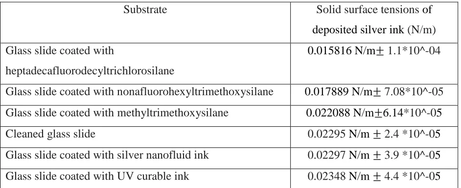
was 0.02355*10^-4 N/m. The solid surface tensions of silver ink on different substrates can be found in Table 1.
Substrate Solid surface tensions of
deposited silver ink (N/m) Glass slide coated with
heptadecafluorodecyltrichlorosilane
0.015816 N/m± 1.1*10^-04
Glass slide coated with nonafluorohexyltrimethoxysilane 0.017889 N/m± 7.08*10^-05 Glass slide coated with methyltrimethoxysilane 0.022088 N/m±6.14*10^-05
Cleaned glass slide 0.02295 N/m± 2.4 *10^-05
[image:6.612.72.543.197.389.2]Glass slide coated with silver nanofluid ink 0.02297 N/m± 3.9 *10^-05 Glass slide coated with UV curable ink 0.02348 N/m± 4.4 *10^-05
Table 1. Solid surface tensions of silver ink on different substrates.
Theoretical approach
Analytical analysis
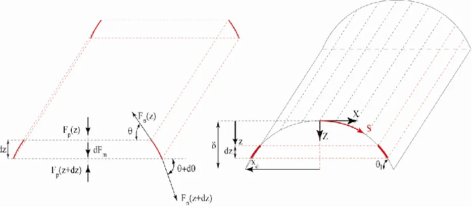
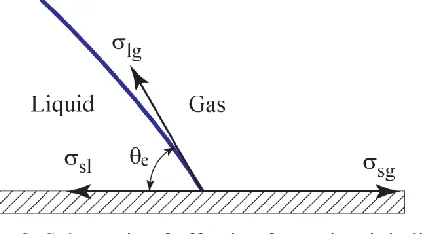
Figure 2 shows the schematic of the force balance on a slice of a long droplet or printed line between z and z+dz along the vertical axis. The force balance along the vertical axis can be expressed as follows:
0 )
sin( ) ( ) sin(
) ( ) ( )
(z Fp zdz F zdz d F z dFm p
F (3)
where the surface tension, F(z), pressure,Fp(z), and gravity forces, dFm, are: L
z
F( )2lg (4)
xL o R gz g l z p
F ( )[( ) lg]2 (5)
Lxdz g g l m
7 expression was obtained for long droplets as:
0 sin ) 2 ( lg 2 ) ( l o R d x d x c A g g
l
(7)
Equation (7) gives a relationship between cross sectional area, c
A , width, d x
2 , radius of curvature at apex,
o
R , and long droplet contact angle, l
. Where l ,
g and
lg
are the liquid
[image:7.612.74.541.224.429.2]density, gas density and liquid-gas surface tension respectively.
Figure 2. Schematic of force balance in vertical direction on a slice of a long droplet or printed line between z and z+dz.
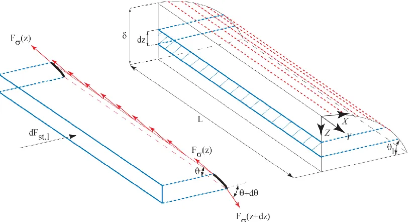
Figure 3 shows the schematic of the force balance along the lateral axis for the long droplet or printed lines. Similarly, the force balance was written along the lateral axis as:
0 ) cos( ) ( cos ) ( ,
dFstl F z F z dz d (8)
where the static force, l st dF
, , along the lateral axis is:
gzLdz g l Ldz o R l st
dF , lg ( )
(9)
Simplifying equation (8), another analytical expression was derived as 0 cos 1 2 lg 2 ) (
1
l g
g l o
R
8
Figure 3. Schematic of force balance in lateral direction on slice of long droplet or printed line between z and z+dz.
For printed lines, ourexperimental evidence demonstrates that the second term in equation (10) is negligible compared to the rest of terms, therefore the contact angle can be assumed to be independent of gravity and droplet size.
By writing the force balance along the front axis (Y), another analytical expression was derived. 0 2 2 2 lg ) ( 1 1 2 dx dz x z g g l o R dx dz (11)
In order to simplify equation (11), dx dz
in the second term of equation (11) was assumed to be
equivalent to
) 1 (z c
y
, as the long droplet contact angle is size independent, see equation (10).
The modified form of equation (11) can therefore be written as:
0 2 1 2 2 lg ) ( 1 1 2 c z y x z g g l o R dx dz (12)
9 z g g l o R dx dz dx z d lg ) ( 1 2 / 3 ) ( 1 2 2 2 (13)
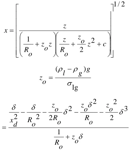
combined with equation (12), was solved analytically to predict the profile of the long droplet or printed line as:
2 / 1 2 2 1 c z o z o R z z o z o R z
x (14)
lg ) ( g g l o z
(15)
o z o R o z o R o z o R o z o R d x c 1 3 2 2 2 2 2 2 2 (16)
[image:9.612.203.427.213.455.2]Numerical prediction of printed line
Figure 4 shows the schematic of the long droplet or printed line. The Young-Laplace equation can be written as:
) ( lg 2 g l gz o R ds
d
[image:9.612.191.424.539.672.2](17)
Figure 4. Schematic of long droplet or printed line.
10
differential equations and boundary conditions, to predict the profile of the long droplet or printed line.
cos ds dr
(18)
sin ds dz
(19) 0
) 0 ( ) 0 ( ) 0
( z
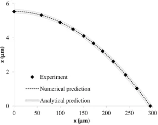
[image:10.612.145.465.262.514.2]r (20) Figure 5 shows the comparison between experimental data, numerical and analytical solutions of the profile of a printed line using a nanofluid silver ink on glass substrate.
Figure 5. Comparison between experimental data, numerical and analytical solutions of printed line by nanofluid silver ink on glass substrate.
Results and discussions
As surface wettability decreases, (a) the merging phenomenon becomes more effective and the printed lines become more discontinuous (see Figure 6), as a result printing of continuous lines becomes more difficult. (b) The substrate is able to hold more ink before the triple line becomes unpinned or unstable (see Figure 7). In other words, the cross sectional area and volume of printed lines increases with a reduction of wettability, for a nanofluid ink this leads to an increase in the volume of the deposited line and a consequent increase in the deposited active material, for printed
0 2 4 6
0 50 100 150 200 250 300
z (
m)
x (m) Experiment
11
electronics applications this could lead to a reduction in resistance for example. However, printing on to the substrates becomes more difficult as hydrophobicity of the nanofluid ink for the substrate increases.
[image:11.612.74.540.476.557.2]Figure 6 shows the image of the printed line on a glass substrate coated with heptadecafluorodecyltrichlorosilane, (a) after a first layer with 40mdrop spacing, (b) after 5 layers with 40mdrop spacing and (c) after 11 layers with 40mdrop spacing. In the first 11 layers, the main issue was to create a continous line and subsequently, the focus was to prevent the bulging phenomenon. The reduction of drop spacing and temperature enhancement of the substrate (40-60ºC) could be used as effective techniques to print a continous line in the first layers. However, raising the temperature of the substrate plays a negative role in preventing the bulging phenomenon after the first 11 layers, due to the reduction of the liquid-gas surface tension of the nanofluid inks with temperature. Another possibility was to raise the substrate temperature for the first layers until the printed line becomes continous and reduce the temperature for subsequent layers which can increase the printing time. In this research, the first 11 layers were printed with 40mdrop spacing at ambient temperature. To prevent the bulging phenomenon after the first 11 layers, the printing flow rate decreased by increasing of drop spacing from 40mto 60m and reducing the number of rows from 10 to 2 for each layer. Printing was continued until the triple line became unstable or unpinned. A similar strategy was used to print on a clean glass slide and glass slides coated with nonafluorohexyltrimethoxysilane and methyltrimethoxysilane.
Figure 6. Images of printed lines on glass slide coated with heptadecafluorodecyltrichlorosilane, (a) after first layer with 40mdrop spacing, (b) after 5 layers with 40mdrop spacing and (c) after 10 layers with 40mdrop spacing.
12
continued until the triple line became unpinned or unstable. The cross sectional area of the printed line was observed to increase with a reduction of solid surface tensions,
sl sg
. In fact, the
triple line spreads more toward the gas phase as solid surface tensions increases (see Figure 8).
[image:12.612.74.537.148.331.2]Figure 7. Variation of cross sectional profile of printed lines on the clean glass slide and glass slides coated with hptadecafluorodecyltrichlorosilane, nonafluorohexyltrimethoxysilane and methyltrimethoxysilane.
Figure 8. Schematic of effective forces in triple line.
[image:12.612.205.420.410.527.2]13
Substrate sl
sg f
w ture
Microstruc sl
sg f w sl
sg
(1 ) (21)
d D
D f
w
(22)
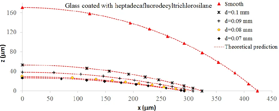
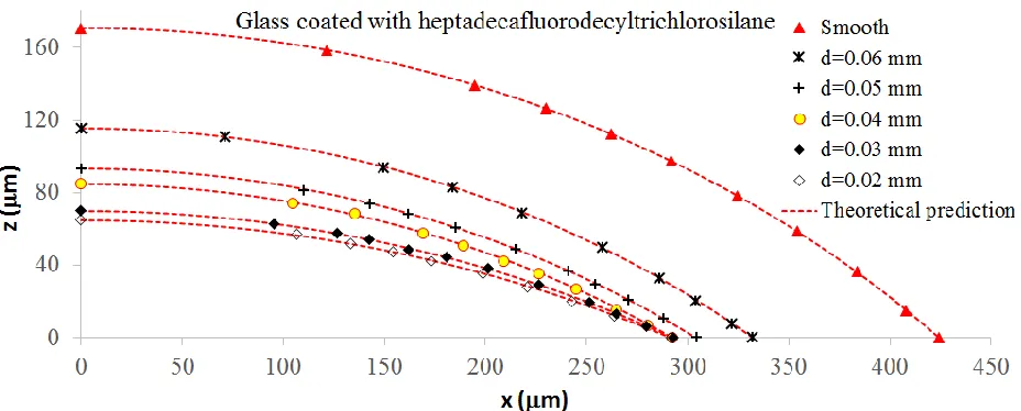
The average solid surface tensions increased with reduction of distance between micro-structured dots, d. Figures 7, 10 and 11 show that the cross sectional profile of printed line is a function of solid surface tensions. The solid surface tensions plays a significant role on the force balance, spreading and behaviour of the triple line, since the liquid-gas surface tension remains constant
during printing.
[image:13.612.134.542.71.142.2] [image:13.612.192.423.254.376.2]
Figure 9. Schematic of UV curable micro-structure pattern on the glass slide coated with heptadecafluorodecyltrichlorosilane.
[image:13.612.74.540.452.638.2]14
Figure 11. The variation of cross sectional profile of printed lines on the micro-structured glass slides coated with heptadecafluorodecyltrichlorosilane. The coated glass was micro-structured with nanofluid silver ink.
Conclusions
Surface wettability has an important role in inkjet printing including controlling of the feature size and cross sectional profile of the printed lines which can have a key impact on the performance of the printed system i.e. the conductivity of printed lines for a given resistivity. Surface wettability depends on solid surface tensions at the triple line for a given nanofluid ink. The spreading of the triple line on a substrate decreases with a reduction of the solid surface tensions which enables one to (a) create lines with lower width and (b) enhance the cross sectional area of the printed line. This consequently increases the volume of nanoparticles within the printed line. The solid surface tensions were modified, using coating and micro-structuring of the substrates. Since the substrate can be micro-structured, using the same inkjet printer, 3D printing on to a micro-structured substrate is an alternative method to coating of the entire substrate, this is especially important where the ability to deposit numerous materials in a single layer is desired.
15 Acknowledgment
The authors gratefully acknowledge the support of the funders, the UK’s Engineering and Physical Science Research Council (EPSRC: EP/I033335/2) through the Centre of Innovative Manufacturing in Additive Manufacturing. The authors would like to thank Yinfeng He for providing the UV curable materials.
References
Adams J.J., Slimmer S.C., Lewis J.A. And Bernhard J.T., 3D-printed spherical dipole antenna integrated on small RF node, Electronics Letters, 2015 Vol. 51 No. 9 Pp. 661–662.
Cummins, G., Desmulliez, M. P.Y., 2012, Inkjet printing of conductive materials: A review, Circuit World, 38, 193-213.
Duineveld, P. C., 2003, The stability of ink-jet printed lines of liquid with zero receding contact angle on a homogeneous substrate, J. Fluid Mech. 477,175-200.
Jang, D., Kim, D., Moon, J., 2009, Influence of fluid physical properties on ink-jet printability, Langmuir, 25, 2629-2635.
Kang, H., Soltman, D., Subramanian, V., 2010, Hydrostatic optimization of inkjet-printed films, Langmuir, 26, 11568-11573.
Lee, S. H., Shin, K. Y., Hwang, J. Y., Kang, K. T., Kang, H. S., 2008,Silver inkjet printing with control of surface energy and substrate temperature, J. Micromech. Microeng 18, 0750141-7. Lee, S. H., Cho, Y. J., 2012, Characterization of silver inkjet overlap-printing through cohesion and adhesion, J. Elec. Eng. Tech. 7, 91-96.
Smith, P. J., Shin, D. Y., Stringer, J. E., Derby, B., 2006, Direct ink-jet printing and low temperature conversion of conductive silver patterns, J. Mater Sci. 41, 4153-4158.
Stringer, J., Derby, B., 2010, Formation and stability of lines produced by inkjet printing, Langmuir 26, 10365-10372.
Shin, K. Y., Lee, S.H., Oh, J.H., 2011, Solvent and substrate effects on inkjet-printed dots and lines of silver nanoparticle colloids, J. Micromech. Microeng. 21, 0450121-11.
Soltman, D., Subramanian, V., 2008, Inkjet-printed line morphologies and temperature control
of the coffee ring effect, Langmuir, 24, 2224-2231.
16