Published online in Wiley InterScience (www.interscience.wiley.com). DOI: 10.1002/spe
A Transformation-based Approach to Testing Concurrent
Programs using UML Activity Diagrams
Chang-ai Sun
1∗, Yan Zhao
1, Lin Pan
1, Xiao He
1, and Dave Towey
21School of Computer and Communication Engineering, University of Science and Technology Beijing, China 2School of Computer Science, The University of Nottingham Ningbo China, China
SUMMARY
UML activity diagrams are widely used to model concurrent interaction among multiple objects. In this paper, we propose a transformation-based approach to generating scenario-oriented test cases for applications modeled by UML activity diagrams. Using a set of transformation rules, the proposed approach first transforms a UML activity diagram specification into an intermediate representation, from which it then constructs test scenarios with respect to the given concurrency coverage criteria. The approach then finally derives a set of test cases for the constructed test scenarios. The approach resolves the difficulties associated with fork and join concurrency in the UML activity diagram, and enables control over the number of the resulting test cases. We further implemented a tool to automate the proposed approach, and studied its feasibility and effectiveness using a case study. Experimental results show that the approach can generate test cases on demand to satisfy a given concurrency coverage criterion, and can detect up to 76.5% of seeded faults when a weak coverage criterion is used. With the approach, testers can not only schedule the software test process earlier, but can also better allocate the testing resources for testing concurrent applications. Copyright c⃝2014 John Wiley & Sons, Ltd.
Received . . .
KEY WORDS: Software Testing; Scenario-oriented Testing; Concurrent Programs; UML Activity Diagrams
1. INTRODUCTION
The Unified Modeling Language (UML) [28] is the de-facto standard for modeling software systems. UML captures different aspects of the system and provides different diagrams to specify, construct, visualize and document artifacts of software-intensive systems. UML 2.0 [8] defines 13 diagrams types, which can be classified into structure, behavior and interaction categories. Based on these, implementation of systems can be further automated using code generation. Since software engineering economics indicates that software testing should be performed in earlier stages of the software development process, it is important to design test cases as early as possible, leading to an increasing demand for testing techniques which derive tests directly from UML diagram specifications.
In recent years, much research has looked at test case generation from various UML diagrams, such as Class Diagrams [5][32], State Diagrams [3][7][13][17][19][26][36][40],
∗Correspondence to: School of Computer and Communication Engineering, University of Science and Technology
Beijing, Beijing 100083, China. E-mail:[email protected]
†A preliminary version of this paper was presented at the 32nd Annual IEEE International Computer Software and
Sequence/Collaboration Diagrams [27][38], Use Case Diagramss [14], Activity Diagrams [33][34], and the combination of Use Cases and State charts [30].
UML Activity Diagrams (UADs) are widely used to model business workflow and the concurrent behavior of large-scale complex systems, and therefore many domains and applications are most easily rendered by such flow-based descriptions. They describe how multiple objects collaborate to implement a set of specific operations or functional scenarios, and the scenarios described correspond to the business workflow in the implemented systems. Because of this, we believe that test cases generated from activity diagrams as the basis of functional testing, especially for testing concurrent behavior, are both appropriate and well-suited for validating the correctness of the entire system [33].
When generating tests from UADs, we first need to construct a set of test scenarios, which represent a sequence of performed operations in a software system. When the system to be tested is complex, the number of test scenarios may be huge, and therefore one challenging task is how to derive a comprehensive test scenario suite from UADs. Clearly, automatic test scenario generation would be particularly desirable, but automatic UAD-based test case generation faces the following difficulties [33][34]:
(1) Some characteristics of the UADs may cause challenges for the generation of test scenarios. In particular, the fork and join activities are commonly used to model concurrent applications, but they have some special semantics which are different to the common branch structures, including that only one branch will be executed when its corresponding condition holds, but all parallel activities between a fork and its corresponding join must be executed.
(2) Exhaustive coverage of UAD concurrency and branch features could lead to a huge number of test scenarios, not all of which could be tested, because some infeasible test scenarios correspond to unreachable paths.
In our previous work [42], we developed a three-layer framework for generating test cases based on specifications in the form of UADs. An important contribution of this work was a set of transformation rules. Since UADs often contain elements associated with fork and join branches and concurrent flows, the approach first converts the UAD into a set of Extended AND-OR Binary Trees (EBTs) — a standardized intermediate structure. However, how to handle loops in UADs and how to generate test scenarios from the transformed specification (i.e. EBTs) was not addressed. In [34], we proposed a recursive algorithm to directly generate test scenarios from UADs with respect to a basic path coverage criterion, and also developed a tool to automate the algorithm. Note that this algorithm was not based on the transformed specification.
In this paper, we propose a transformation-based scenario-oriented approach to testing programs whose behavior is described using UADs. All fork and join elements are eliminated during the transformation, with concurrent structures represented as binary trees to avoid the path explosion problem during test case generation. Next, the approach generates test scenarios from the EBTs according to a coverage criterion for concurrent flows. In this paper, we present a transformation-based scenario-oriented testing framework, develop a prototype tool to automate this framework, and present a case study to examine the applicability and effectiveness of the proposed approach. The main contributions of this paper, together with its preliminary version [33], are fourfold:
(i) We propose a transformation-based scenario-oriented testing framework and develop transformation rules for converting a UAD to a standardized intermediate structure;
(ii) We propose concurrency coverage criteria for testing concurrent behavior, and develop a set of algorithms for generating test scenarios with respect to a specific criterion;
(iii) We develop a tool to automate the proposed framework and to interact with UAD-supported tools; and
(iv) We conduct a case study to validate the feasibility and effectiveness of the proposed approach.
5 describes a case study to validate the feasibility and effectiveness of the proposed approach; Section6discusses some related work; and Section7presents the conclusion and some discussion about future work.
2. BACKGROUND
In this section, we introduce some of the underlying concepts of UADs, model-driven testing, and mutation analysis.
2.1. UML Activity Diagrams
The Unified Modeling Language (UML) provides a set of diagrams which enable developers to specify a system from different views, one of which is the UML Activity Diagram (UAD), which is widely used for behavior modeling. The UAD can be used to depict the control flows of a certain operation in the system, or for the entire system, supporting all control structures, such as sequences, loops, branches, and concurrency.
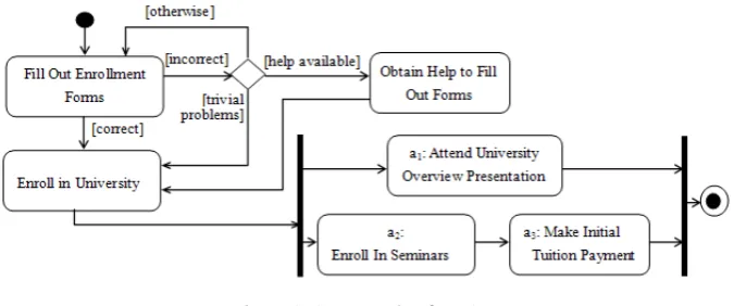
[image:3.595.129.467.466.607.2]A UAD usually consists of activities, transitions, decision points, guards, parallel activities, swimlane guidelines and action-object guidelines. Figure1shows an example of a UAD [1] which models the workflow of a university enrollment system. Astartpoint and anendpoint are modeled as a filled circle and a filled circle with a border around it, respectively. Atransitiondescribes the data-flow or control-flow between two activities. Adecision point(modeled as a diamond) concerns selection of the following activities based on those preceding the decision point. Thedecisionpoint is sometimes called a branchactivity ormergeactivity. Aguard (depicted using the format [· · ·] on the transitions) is a condition that must be true in order to traverse a transition. For example, the decision point in Figure1has three exiting transitions, each of which has a guard condition. To traverse the direct transition from the decision point to the activity “Enroll in University”, the guard condition [trivial problems] must be true.Parallelactivities (depicted using two parallel bars) are used to show that activities can occur in parallel. The first bar (e.g. the left one in Figure1) and the second one (e.g. the right one in Figure1) are calledforkandjoinactivities, respectively. In some situations, calledloops, an activity repeats until a specific condition is satisfied — these structures have two incoming and one outgoing transition. Each activity in a UAD, therefore, is either anaction, astart, anend, afork, ajoin, abranch, amerge, or alooptype.
Figure 1. An example of a UAD
semantics of parallel activities and decision points, automatic derivation of such test scenarios from a UAD is a difficult task, and when the system under development is large and complex, the combination or nesting of optional behavior and concurrent behavior may make test scenario generation even more difficult.
2.2. Model-driven Testing
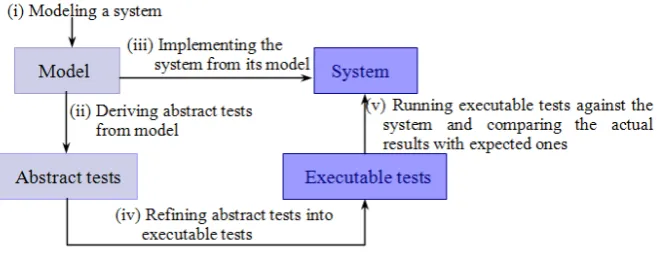
[image:4.595.135.464.281.408.2]Modeling is an important and necessary step in the development of large-scale software-intensive systems: it usually captures the important system aspects, and thus enables exploration and analysis of key points and properties. MDT (Model-Driven Testing) [9] is a testing method based on the modeling artifacts. As illustrated in Figure 2, MDT usually consists of the following steps: (i) Modeling a system; (ii) Deriving abstract tests from the model; (iii) Implementing a system from the model; (iv) Refining the abstract tests into executable tests; and (v) Running the executable tests against the system and comparing the actual results and expected ones. MDT makes the testing (steps ii and iv) and coding (step iii) of a system parallel jobs, thus enabling testers to start designing tests at the modeling phase rather than waiting until the implementation phase, something particularly useful when the schedule is tight and/or testing resources are limited.
Figure 2. The main steps of MDT
Given the widespread use of UML, an interesting question is that of how to test a system based on its UML diagrams. In this paper, we investigate how to effectively and efficiently test a system with concurrent behavior based on its UAD. A key issue is to generate test scenarios from the UAD, and use these scenarios to help discover defects earlier.
2.3. Mutation Analysis
Mutation analysis is a fault-based testing technique which hypothesizes certain types of faults that may be injected by programmers, and then designs test cases targeted at uncovering such faults [10]. Mutation analysis has also been widely employed to evaluate the effectiveness of various software testing techniques [35]. It applies mutation operators (each describing a simple syntactic change to the code) to seed faults into the program under test, thereby generating a set of faulty versions, called mutants. After creating the mutants, a set of test cases is executed on them. When a test case results in a mutant producing different (incorrect) output compared with the original program, then we say that that mutant is “killed”. The mutation score(MS)measures the adequacy of a set of test cases. It is defined as follows:
M S(p, t) = Nk Nm−Ne
(1)
whereprefers to the program being mutated,tis the test suite,Nk is the number of killed mutants,
Nm is the total number of mutants, and Ne is the number of equivalent mutants. An equivalent
3. TRANSFORMATION-BASED SCENARIO-ORIENTED TEST CASE GENERATION
In this section, we present a transformation-based scenario-oriented test case generation method based on UADs.
3.1. Overview
Generating test cases from UADs is a kind of model-driven testing technique which can be more challenging than traditional black-box or white-box testing due to the fact that there are multi-design aspects which are usually separate. We assume that sufficient information has been provided in the UAD specification, and that it contains no inconsistencies. These two assumptions are justifiable because UML-based software development emphasizes modeling the system’s structure and behavior in order to support automatic code generation. This means that sufficiently detailed information is provided in the design model, and inconsistency checking is performed before testing begins.
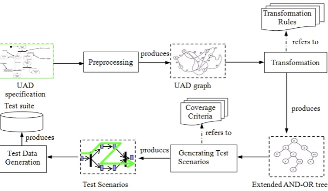
To deal with the challenges in activity diagrams due to forkand join activities, we propose a transformation-based approach to generating test cases, focusing mainly on the testing of concurrent activities (illustrated in Figure3). The approach includes the following four major steps:
1. Preprocessing: Parse the UAD specification (often represented in an XML Metadata Interchange (XMI) file) to produce a UAD graph model, which not only contains a set of activity and transition entries, but also has essential information for the test case generation. 2. Transformation: Based on a set of transformation rules, convert the UAD graph into an
intermediate representation called an Extended AND-OR Binary Tree (EBT). This results in fork and join elements being eliminated, and other branches (including loops) and concurrent flows all being represented as EBTs. Using such a standard representation, test scenario generation algorithms can easily be developed.
3. Generating test scenarios: Traverse the derived EBTs to generate a set of test scenarios with respect to the given concurrency coverage criteria. The EBTs are a general test specification language based on which we can develop algorithms satisfying different concurrency coverage criteria.
4. Test data generation: For each test scenario, derive test data by selecting the corresponding decisions along the test scenario. To do this, we can first randomly generate a test data pool, and then select the appropriate data as test cases. In our future work, we will use constraint solver techniques to automatically generate the test data for each test scenario.
We next discuss in detail the main steps of the proposed approach.
3.2. Preprocessing
Most existing UML tools (such as IBM Rational Rose† and ArgoUML‡) support UAD modeling. In order to facilitate the exchange of modeling artifacts, UML specifications are normally stored as XMI (XML Metadata Interchange) files. To generate tests from the UAD specifications, we need to extract the elements or properties that are essential for testing. Such preprocessing has two implications: (1) We can skip those elements or properties unrelated to testing; and (2) Transformation rules and test scenario generation algorithms can be developed without being restricted to a specific input format — thus they are reusable.
For each activitya, we extract an entry<ID,resposeID,noOutTransitions,type,name>, where
- IDis the unique label ofa. All activities are labeled as follows:
(1) Starting from zero and labeling in order the activities fromstarttoend.
Figure 3. An illustration of the transformation-based framework
(2) When abranchorforkactivity is encountered, labeling the activities in order along the path until all activities have been processed.
(3) When an activity whosenoOutTransitionsis greater than two is encountered, if the ID of the following activity has been assigned, then skipping over this path; otherwise, switching to another following activity and repeating steps (1), (2), and (3).
- responseIDis a specially designed label which is used to identify the hierarchy of the activity. It is defined as follows:
- If the type isstart,action, orloop, itsresponseIDis the ID of next activity whose type is notaction;
- If the type isbranch, itsresponseIDis the ID of its correspondingmergeactivity; - If the type isfork, itsresponseIDis the ID of its correspondingjoinactivity; - If the type ismergeorjoin, itsresponseIDis equal to its ID plus 1.
- If the type isend, itsresponseIDis its own ID.
- noOutTransitionsis the number of transitions leading to activities froma.
- typeis the type ofa— eitherstart,end,action,f ork,join,branch,merge, orloop. - nameis the name ofa.
For each transitiont, we extract an entry<iID,oID>, where
- iIDis the ID of the incoming activity oft. - oIDis the ID of the outgoing activity oft.
We store the extracted activities and transitions in a UAD graph structure, which is defined as follows.
Definition 1 (UAD Graph):A UAD graph is a 4-tuple< A, T, C, L >, whereT :A×C→A, and where:Ais the collection of activity entries;T is the set of transitions;Cis the set of constraint conditions that must be satisfied when transitions in T happen; and L is a label function which assigns a unique label to each activity and transition.
3.3. Transformation
In the next step, our approach converts the UAD graph into an EBT using a set of transformation rules. We next provide a formal definition of an EBT, and then present the transformation rules.
Definition 2 (EBT): An EBT is a tuple < N, E, ψ >, where N =−→A + {BOR, MOR, FAND,
are extendedORnodes designed forbranchandmergeactivities, respectively;FANDandJANDare extendedANDnodes designed forforkandjoinactivities, respectively;CYCLEis designed forloop
activities;Eis a set of two-tuples< n1, n2>wheren1∈Nandn2∈N; andψis a function which
assigns a unique label for each node and edge.
Rule 1 (Transformation rule for anaction activity): A common UAD actionactivity does not require special treatment, and is converted into anormalnode, and stored as a left child of the EBT. Thestartactivity should be converted into a root node of the EBT, and theend activity should be converted into a leaf node.
Rule 2 (Transformation rule for abranch orfork activity): For a UADfork activity with two outgoing transitionst1, t2∈T, (wheretiis(a, ci)→ai,1≤i≤2,ci∈C,ai ∈A) generate a node
nto replacea, and add a logical nodeF AN D. ConnectnandF AN Dwith an edge labeledNULL, and set the outgoing transition edges ofF AN DtoF AN D−→e1 n
1andF AN D−→e2 n2, where e1 and e2 are the mapped edges of transitions t1 and t2 in the UAD’sT; andn1 and n2 are the
mapped nodes of activitiesa1anda2in the UAD’sA.
[image:7.595.189.408.260.348.2]The transformation of abranchactivity is similar to that forfork, but replacingFANDwithBOR.
Figure 4. Transformation of aforkactivity
With the above transformation rule, we can convert a fork activity into an EBT by first creating a corresponding node and then adding aF AN Dnode as its left child; we then treat the two following parallel activities as the left and right child nodes of the F AN D node. Figure 4illustrates this transformation of aforkactivity. For abranchactivity, we first create a corresponding node, add a
BORnode as its left child, then treat the two following branch activities as the left and right child nodes of theBORnode.
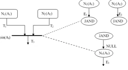
Rule 3 (Transformation rule for a join or merge activity): For a UAD join activity a with multiple incoming transitionst1, . . . , tm∈T (wherem≥2,tiis(ai, ci)→a,1≤i≤m,ci∈C,
and ai ∈A), generate a node n to replace a and add a logical node J AN D. Connect n and
J AN Dwith an edge labeledN U LL; and set the incoming transition edges ofJ AN Dton1−→e1 J AN D, . . . , nm−→em J AN D, wheree1, . . . , emare the mapped edges of transitionst1, . . . , tmin
the UAD’sT; andn1, . . . , nmare the mapped nodes of activitiesa1, . . . , amin the UAD’sA.
The transformation of amergeactivity is similar to that forjoin, but replacingJ AN DwithM OR.
Figure 5. The transformation of ajoinactivity
[image:7.595.194.408.547.664.2]preceding parallel activity as a parent of theJ AN Dnode. Figure5illustrates this transformation of ajoinactivity. Similarly, for amergeactivity, we first create a corresponding node, add aM OR
node as its parent, and then treat each preceding branch activity as a parent of theM ORnode.
Rule 4(Transformation rule for amulti-forkormulti-branchactivity): For a multi-fork activitya
with more than two outgoing transitionst1, . . . , tm∈T, wherem >2, the transformation is done
as follows: (i) create a correspondingN U LLnodea′to replacea, and add a logicalF AN Dnode
f as its left child; (ii) randomly select an unprocessed following parallel activity as the left child of f (using Rule 2), and add a logical node F AN D f′ as the right child; (iii) if the number of the following unprocessed parallel activities is more than one, go to step (ii); otherwise, set the following unprocessed parallel activity as the right child off′.
[image:8.595.194.408.226.320.2]Figure 6 illustrates the transformation of a fork activity. The transformation of a multi-branch activity is similar to that for multi-fork, but replacingFANDwithBOR.
Figure 6. The transformation of amulti-forkactivity
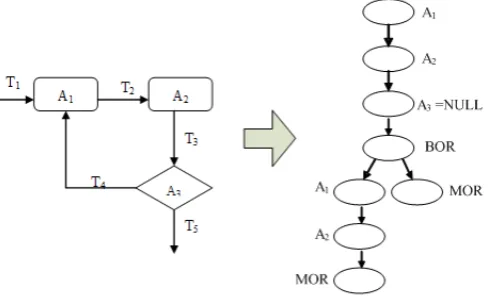
Unlike a common action activity, a loop activity has two incoming and one outgoing transition, as illustrated in the left part of Figure7. We identify loop activities using the concept of post-activities, which is defined next. An activityais aloopactivity if and only ifais subsumed in its post-activities.
Definition 3 (Post-Activities of an activity): Given an activity a in the UAD, the post-activities of a are defined as postActivities(a+) =a1∪a2, ...,∪an, where
a1=postActivities(outT ransitions(a)),· · · , an =postActivities(outT ransitions(an−1)); outT ransitions(a)is a set of outgoing transitions of a; and postActivities(t)is a set of target activities of transitiont.
We convert aloop activity into the combination of onemergeactivity and the original activity, as illustrated in the right part of Figure7. After the transformation, one fakemergeactivityA′ and one fake transitionT′ are introduced into the converted UAD. The transformation does not cause additional elements from the point of view of testing, but it does have problems: the mergeand
branchnodes do not match; and themergenode is ahead of thebranchnode, which will cause the test scenario derivation algorithm (to be described later) to fail. Considering that each conditional branch of the loops should be covered at least once from the point of view of testing, we next propose a transformation rule for a loop activity.
Rule 5 (Transformation rule for a loop activity): For a UAD loop activity with two incoming transitions t1, t2∈T (where t1 is (ax, c1)→a; t2 is (ay, c2)→a; ax, ay ∈A; and
[image:8.595.159.437.597.685.2]ay ∈postActivities(a+)), generate acyclenodento replacea, and generate a sequence of nodes
Figure 8. The transformation of aloopactivity
nito replace activities inpostActivities(a+)\ay(nand nodesniare referred to as theloop body).
Add a logical nodeBORand one logical nodeMOR, and connect them; add another logical node
MOR, connectBORto theloop body, and connect theloop bodytoMOR.
With the above transformation rule, we can convert aloopactivity into a set of EBTs. We first create a sequence of nodes to represent the loop body, then create two branches as leaves of the
BORnode: one is the loop body (as the left child), and the other isempty (as its right child); both of them end with aMORnode. Figure8shows this transformation of theloopactivity illustrated in Figure7.
We developed the algorithm shown in Figure9to implement the automatic transformation. The algorithm reads in a UAD graph model and outputs a set of EBTs. It traverses all activities in the graph model and handles each activity according to its type. The conversions are conducted based on the transformation rules above: (i) if the current activity is an action activity, convert it to a
NORMALnode and add it to the EBT; (ii) if the current activity is aforkorbranchactivity, create aFANDorBORnode and add it to the EBT, then get the child activities of the current activity and convert them recursively; (iii) if the current activity is a joinormergeactivity, create a JANDor
MOR node and add it to the EBT, then get the child activities of the current activity and convert them recursively; (iv) if the current activity is aloopactivity, create aCYCLEnode and add it to the EBT, and then recursively get the child activities and convert them.
Although a theoretical proof of the transformation’s correctness would be ideal, it is well known that the UML is a visual formal modeling language with a limited formalism, and the semantics of UADs is provided in UML standard manual. Given the difficulty in proving the transformation correctness, we instead turn to testing to validate the transformations.
3.4. Generating Test Scenarios
A UAD describes the important business scenarios of a system being modeled, with a path leading from a start activity to an end activity forming a test scenario. The question of generating test scenarios from UADs, therefore, is reduced to one of deriving executable paths from a directed graph. With the proposed transformation rules, we can now convert UADs containing fork and join concurrency into extended binary trees (EBTs). Here, we discuss how to derive test scenarios from the EBTs.
Definition 4 (Test scenario):A test scenarioT S, derived from a UAD, is a sequence of activities
{a1, a2,· · · , an}, whereai(i= 1..n)∈Aof the UAD (the type of eachai(i̸= 1∧i̸=n) is one of
action,fork,join,branch,merge, orloop; anda1 andan are thestartandendnodes of the UAD,
respectively). There must be a transition between anyai andai+1(i=1..n-1), oraiandai+1 must
Generating test scenarios is a key step in the generation of test cases. Because it is usually impossible or infeasible to test all possible paths (due to limited testing resources), three coverage criteria [33] have been proposed:
1. Weak concurrency coverage. Test scenarios are derived to coveronly onefeasible sequence of parallel processes, without considering the interleaving of activities between parallel processes.
2. Moderate concurrency coverage. Test scenarios are derived to coverall feasible sequences of parallel processes, without considering the interleaving of activities between parallel processes.
3. Strong concurrency coverage. Test scenarios are derived to coverallfeasible sequences of activitiesandparallel processes.
Consider the parallel activities of the UAD example in Figure 1. For clarity, we denote the activities “Attend University Overview Presentation”, “Enroll in Seminar(s)” and “Make Initial Tuition Payment” as a1, a2, and a3, respectively. When the weak concurrency coverage is
used,either“a1→a2→a3” or “a2→a3→a1” should be tested; for themoderate concurrency
coverage, both “a1→a2→a3” and “a2→a3→a1” should be tested; and for the strong
concurrency coverage, “a1→a2→a3”, “a2→a3 →a1”, and “a2→a1→a3” should all be
tested. Clearly, these concurrency coverage criteria require that the derived test scenarios cover each parallel process at least once. Both weak and moderate concurrence coverage test the activities and control flows within a parallel process in a sequential way. Strong concurrency coverage considers the crossing of activities and control flows from parallel processes, which may result in a huge number of test scenarios, and thus may be impractical. Our proposed approach has so far implemented only the weak and moderate concurrency coverage.
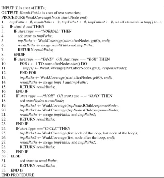
We propose an algorithm (shown in Figure10) to generate test scenarios from EBTs, with respect to weak concurrency coverage. The algorithm generates test scenarios from astartnode to anend
node recursively. The algorithm first traverses all the nodes of each EBT to generate test scenarios according to their types, and then combines all partial test scenarios for each part to form complete test scenarios. We next briefly explain this algorithm.
• If thestart node is a NORMAL node, add it to the generated test scenario, and process the next following node.
• If thestartnode is aFANDorBORnode, first create two scenarios: one from thestartnode to the matching response node that is specified by itsresponseID, and the other from the first node after the matching response node to theendnode; then merge these two scenarios together.
• If thestart node is aJANDorMORnode, traverse all nodes starting from the start node of another EBT.
• If thestart node is aCYCLEnode, first create two scenarios: one from the first node to the last node in the loop, and another from the first node after theCYCLEto the last node; then merge them together.
• If thestartnode is the END node, add it to the generated test scenario, and return the resulting sequence.
Because the algorithm in Figure10traverses all nodes in the EBTs, its complexity is proportional to the number of nodesn, namelyO(n).
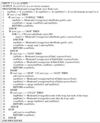
We also propose an algorithm to generate test scenarios satisfying the moderate coverage criteria, as shown in Figure11. The algorithm is similar that in Figure10, except that additional processing is required in relation to the FAND node (permutation between the node and its corresponding
responseIDnode).
• If thestartnode is a NORMAL node, add it to the generated test scenario.
Figure 10. Algorithm for generating test scenarios with weak concurrency coverage
• If the start node is a FAND node, first create three partial test scenarios and store them separately. Then combine the three partial test scenarios to get all possible scenarios.
• If thestartnode is anMOR orJAND node, then process all nodes in another EBT starting from thestartnode.
• If thestartnode is aCYCLEnode, first create two test scenarios: one from the first to the last node in the loop, and the other from the first node after the loop to theendnode; and then merge these two scenarios together,
• If thestart node is the END node, the add it to the generated test scenario, and return the resulting sequence.
The algorithm generates partial test scenarios by only processing each node once in the EBTs. To combine the concurrent nodes, the algorithm needs to repeatedly call a traversal function. Assuming that the number of concurrent nodes ism, then the number of concurrent partial test scenarios ism!, making the overall complexity of the algorithmO(m! +k(nm)), wherenis the number of EBT nodes, andkis a constant.
3.5. Test Data Generation
Figure 11. Algorithm for generating test scenarios with moderate concurrency coverage
scenario is a complete test frame, and a test case with respect to a particular test scenario corresponds to a set of choices whose values can be used to execute the test scenario. Our approach identifies the categories and choices by processing conditions in the branch activities (decision guards), and identifies the dependency relationships between different choices by judging whether these choices occur in the same scenario paths. Finally, we generate test cases by filling in the values for those guards and inputs required in each activity along the scenario path.
Recall the example in Figure 1 (in Section 2.1), the guard condition of the “Obtain Help to Fill Out Forms” activity is “[help available]”, the guard condition of thebranchactivity is “[incorrect]”, and there is a dependency between the choices “[help available]” and “[incorrect]” because the choice “[help available]” holds depending on the choice “[incorrect]”. If a test frame does not satisfy this dependency, it is infeasible; otherwise, it is feasible. For instance, “[incorrect]”→“[help available]” is a feasible test frame, while “[correct]”→“[help available]” is an infeasible test frame.
Next, we randomly generate a large number of test cases without considering possible constraints among the input variables. Finally, we select those test cases that satisfy the guard conditions within a test frame to be part of the test suite. Techniques that can select test case for a program path, such as constraint solver techniques [25], can also be used. In the current study, we give higher priority to boundary valves in order to improve the fault detection capability of our approach, and thus the selection of test cases has been done manually. Automatic test case generation for a specific scenario path is left for our future work.
4. TOOL PROTOTYPE
In this section, we introduce a tool, ConcurTester, developed to automate the proposed approach.
4.1. Features
When UADs are used to model complex business processes or workflow systems, the result may often contain a large number of activities and transitions. Because generating test scenarios from such a UAD is time-consuming and error prone, a tool which could automate the proposed approach is highly desirable.
ConcurTester was developed using Java. It consists of 1966 lines of code, and has the following functionality:
1. Preprocessing: It imports the UAD specification file (in XMI format), and parses it to extract the relevant elements, including activity and transition entries, then stores them as a graph structure.
2. Transformation: It converts the graph structure into EBTs based on the transformation rules. 3. Generating test scenarios: It generates test scenarios from the EBTs with respect to different
concurrency coverage criteria, and presents the generated scenarios for further analysis.
4.2. Pilot test
We use the UAD shown in Figure12to illustrate usage of ConcurTester. First, we import the UAD specification of the system to be tested by clicking theImport Filebutton on the tool. We assume the specification is a standard XMI file generated by ArgoUML§.
After the specification is imported, we click the Convert Filebutton to parse the XMI file and convert it into a graph structure containing the activity and transition entries. When the conversion is finished, a text file is created to store the graph structure.
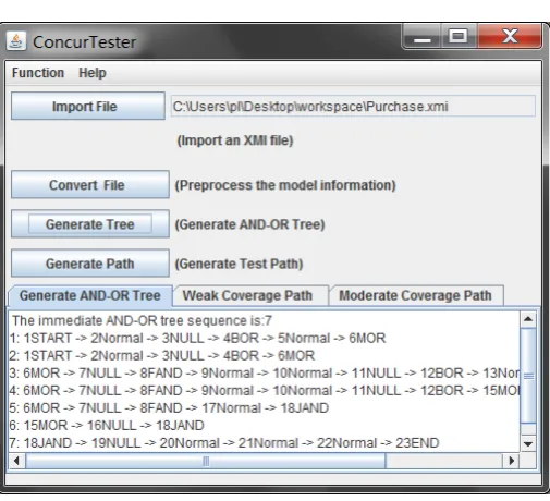
After generating the graph structure, we click theGenerate Treebutton to transform it into EBTs using the transformation rules. The transformation result is presented in the Generated AND-OR Treetab, as shown in Figure13.
After generating the EBTs, we click the Generate Pathbutton to create a set of test scenarios. The“Weak Coverage Path”tab presents the generated test scenarios satisfying the weak coverage criterion (as shown in Figure14), and the“Moderate Coverage Path”tab shows the generated test scenarios satisfying the moderate coverage criterion (as shown in Figure15).
5. CASE STUDY
In this section, we report on a case study conducted to examine the proposed approach and evaluate its effectiveness. In the study, we employed ConcurTester to automatically generate test scenarios, using a product ordering system as subject program. Mutation analysis was used to evaluate the effectiveness of the proposed approach.
§ArgoUML is a widely recognized, open source UML modeling tool, available from the following website:
Figure 12. Theordering productsprocess modelled by UAD
Figure 13. Generated intermediate AND-OR tree sequence of the UAD
5.1. Research Questions
Through this case study, we attempt to answer the following questions:
[image:15.595.171.424.371.601.2]Figure 14. Generated test paths for weak coverage criterion
Figure 15. Generated test paths for moderate coverage criterion
2. What is the fault detection capability of the test suite generated using the proposed approach?
5.2. Experimental Design
We next describe the experimental settings, including the subject program, metrics, mutation, and procedure.
[image:16.595.170.423.323.547.2]UAD [11]. Until now, however, there has not been an implementation available, so we implemented it using Java in a total of281lines of code. In our implementation, the program receives five input parameters, namelymorePro,proNum,proPrice,totalPrice, andshipInfo:moreProindicates if there are remaining order items to be processed;proNumdenotes the number of products;proPriceis the price of each product; totalPrice is the total price of all products; and shipInfo is the transport information.
The UAD in Figure 12 involves various types of activities, including start, end, action
(Getting Shipping Information,Validating Billint Information,Provide Receipt,Assemble Order, and Ship Order), branch, merge, fork, join, and loop activities (Order Prodcuts and
Getting Billing Information).Getting Billing Informationinvolves calculation of cost, comparison of the prices of each product, and comparison of the total price with that of the calculated amount for the number of products; andValidating Billint Informationverifies the cost. Among these activities, the billing information processing (Getting Billing InformationandValidating Billint Information) and shipping information processing (i.e. Getting Shipping Information) are treated as parallel activities, which are accordingly implemented using concurrent threads.
5.2.2. Metrics The effectiveness of the proposed approach was measured using themutation score
(MS), which indicates the adequacy of a test suite for the program under test.
5.3. Experimental Procedure
1. Preprocessing, transformation, and generating test scenarios using ConcurTester: We used ConcurTester to parse the UAD specification (in an XMI file) for product ordering, as illustrated in Figure12. After this, we extracted the collection of activity and transition entries and stored them as a graph structure. Then, ConcurTester was used to transform the graph structure into the intermediate representation (EBTs). During the transformation, all branches and concurrent flows were represented as EBTs. Each loop body was either executed once, or not at all. Finally, ConcurTester generated a set of test scenarios from the EBTs based on a given coverage criterion.
2. Test case generation: We generated a large amount of random test data, from which we selected only those satisfying the generated test scenarios to be in the test suite. As a result, we selected 15 test cases for each test scenario — when the weak coverage criterion was used, four test scenarios were generated in our experiments.
3. Seeding faults: In the study, an open-source mutation system, muJava [22], was used to randomly seed faults into the Java program for product ordering. The muJava system supports
16 types of method-level (traditional) and 29 types of class-level mutation operators¶ of which7method-level and5class-level operators were applicable for our study. Using these applicable operators, a total of170method-level and47class-level mutants were generated, among which 30 method-level and 17 class-level mutants were equivalent, and therefore excluded.
4. Executing tests and collecting the results: We next applied each test in the test suite to both the original program and the mutants, comparing the output. If the output was the same, then the current test passed; otherwise, a fault was detected (and the mutant “killed”). If none of tests could kill the mutant, the test suite failed.
5.4. Results and Analysis
5.4.1. Feasibility For the product ordering system, we extracted the collection of activity and transition entries through preprocessing, as shown in Tables Iand II, respectively. We then used ConcurTester to generate test scenarios. TableIIIshows four test scenarios generated according to the weak coverage criterion. Finally, we generated test data for each scenario.
Table I. The collection of activity entries
ID responseID noOutTransitions type name
0 1 1 start noname
1 2 1 loop Order Product
2 2 2 branch noname
3 8 2 fork noname
4 6 1 loop Getting Billing Information 5 6 1 action Validating Billing Information
6 6 2 branch noname
7 8 1 action Getting Shipping Information
8 9 1 join noname
9 12 1 action Provide Receipt
10 12 1 action Assemble Order
11 12 1 action Ship Order
[image:18.595.254.340.293.496.2]12 12 0 end noname
Table II. The collection of transition entries
iID oID
0 1
1 2
2 1
2 3
3 4
3 7
4 5
5 6
6 4
7 8
6 8
8 9
9 10
10 11 11 12
Table III. Generated Test scenarios using weak coverage criterion
No. Test Scenario
1 noname ->Order Product ->Getting Billing Information ->
Validating Billing Information ->Getting Shipping Information ->
Provide Receipt ->Assemble Order ->Ship Order
2 noname ->Order Product ->Order Product ->Getting Billing Information ->
Validating Billing Information ->Getting Shipping Information ->
Provide Receipt ->Assemble Order ->Ship Order
3 noname ->Order Product ->Getting Billing Information ->
Validating Billing Information ->Getting Billing Information ->
Validating Billing Information ->Getting Shipping Information ->
Provide Receipt ->Assemble Order ->Ship Order
4 noname ->Order Product ->Order Product ->Getting Billing Information ->
Validating Billing Information ->Getting Billing Information ->
Validating Billing Information ->Getting Shipping Information ->
[image:18.595.101.499.518.710.2]5.4.2. Fault detection capability We next analyze the fault detection capability of the test suite generated using the proposed approach. In order to study the impact of the test suite size on the effectiveness of the proposed approach, we varied the size to be4,20,40, and60, which corresponds to 1, 5, 10, and 15 test cases per scenario, respectively. We further compare the fault detection effectiveness of our proposed approach with that of random testing, comparing theirMSscores for the same numbers of test cases.
TableIVpresents theMSresults for each test scenario, displayed according to “Method-level” and “Class-level”. Note that when the evaluation results for different test suite sizes are the same, we merge the evaluation results into one column in order to reduce the redundancies. For instance, for method-level faults, test suites with a size of20,40, and60have the same mutation scores, we show the evaluation results in the “size=20/40/60” row. This reduction rule was also applied to the other tables in this section.
From the table, we can observe that: (i) for both method-level and class-level faults, the generated test suite shows a good fault-detection effectiveness, i.e. the test cases generated using the weak coverage criterion were able to detect more than 45.7% of the method-level faults, and were able to detect more than 73.3% of the class-level faults; (ii) the test suites derived for different test scenarios have a different fault detection capability; (iii) the detection rates of class-level faults appear higher than those of method-level faults; and (iv) the generated test suite size appears to have a slight impact on the fault detection rates of method-level faults. For class-level faults, test suites of different sizes have the same mutation scores, while for method-level faults, test suites whose sizes are20,40, and
[image:19.595.94.501.369.433.2]60have the same mutation scores, and one test suite of size4(namely one test case per test scenario) has slightly lower mutation scores. This further indicates that our approach does not need a large number of test cases for each scenario.
Table IV. TheMSresults using the weak concurrency coverage criterion for each test scenario
Level Number of Test Cases
Test Scenario 1
Test Scenario 2
Test Scenario 3
Test Scenario 4 Method-level size=4 51.4% 45.7% 56.4% 54.3%
size=20/40/60 56.4% 54.3% 63.6% 61.4% Class-level size=4/20/40/60 73.3% 73.3% 86.7% 86.7%
Table Vpresents theMSresults of both our approach and the random approach, according to “Method-level” and “Class-level”, and also overall (“Total”). From the table, we can observe that: (i) the test suites generated by our approach using the weak coverage criterion can detect 100% of non-equivalent class-level faults, regardless of suite size. One test suite of size4 generated by the random approach can detect only 73.3% of non-equivalent class-level faults, while it can detect
100%class-level faults when suite sizes are20,40, and60; (ii) the test suite whose size is4generated by our approach can detect 75.7% of non-equivalent method-level faults, giving an overall detection rate of80%for all seeded faults, whereas the test suite of size4generated by the random approach can detect only 34.3% of non-equivalent method-level faults, giving an overall detection rate of 41.2% for all seeded faults; (iii) test suites whose sizes are20,40, and60generated by our approach can detect 80% of non-equivalent method-level faults, giving an overall fault detection rate of83.5%
for all seeded faults, indicating that increasing the size of test suits composed of randomly generated test cases for each test scenario does not always improve the fault detection rates. Test suites whose sizes are 20,40, and 60 generated by the random approach can detect 69.3% of non-equivalent method-level faults, giving an overall fault detection rate of 74.7%for all seeded faults; and (iv) for the same sizes, test suits generated by our approach achieve higher mutation scores than those achieved by the random approach, with the differences being more prominent when the size is small (with a size of4, their mutation scores are80%and41.2%, respectively).
Tables VI and VII report the mutation scores for the method-level and class-level mutation operators, respectively. Accordingly, we have the following observations:
Table V. The mutation scoreMSresults of our approach and the random approach
Our Approach Random Approach Number of Level Number
of Number of Mutation Score Number of Mutation Score Test Cases Total
Mutants
Killed Mutants
(MS) Killed Mutants
(MS)
Size=4
Method-level 140 106 75.7% 48 34.3% Class-level 30 30 100% 22 73.3%
Total 170 136 80% 70 41.2%
Size=20/40/60
Method-level 140 112 80% 97 69.3%
Class-level 30 30 100% 30 100%
Total 170 142 83.5% 127 74.7%
COI (insert unary conditional operators) method-level mutants, the mutation scores (MS) were100% when our approach was used, which means that the test suite generated using the proposed approach can detect all of these types of faults.
• For ROR (replace relational operators with other relational operators, and replace the entire predicate with true and false) and LOI (insert unary logical operator) method-level mutants, although theMSwas less than100%, it was relatively high, indicating that these faults were relatively easily detected using the proposed approach.
• For AOIS (insert short-cut arithmetic operators) and COR (replace binary conditional operators with other binary conditional operators) method-level mutants, the MSwas low, which suggests that these types of faults were harder to detect, and the test suite generated by the proposed approach cannot detect all such faults. In addition, there were more equivalent mutants in the AOIS type, which further indicates that this type of fault should be treated carefully when designing test cases and doing test specifications.
• For PRV (replace reference assignment with other comparable variable), JTI (this keyword insertion), JTD (this keyword deletion), JSI (static modifier insertion), and JID (member variable initialization deletion) class-level mutants, the mutation scores were100%, which indicates that these types of faults were relatively easy to detect. In particular, the detection rates for all class-level mutants were100%, which suggests that the proposed approach is very effective for such mutants.
• In the same settings, our approach outperforms random testing. For method-level mutants, the mutation scores of our approach are much greater than those for random testing when the size is4; and slightly greater than or equal when the size is20,40, and60. For class-level mutants, test suites whose size is4 generated by random testing cannot guarantee100%detection of JTI and JTD mutants, while test suites generated by our approach can detect100%of all these kinds of mutants, regardless of suite size.
Table VI. The mutation scoresMSfor the method-level mutants using our approach and the random approach
Our Approach Random Approach Number of Mutation Number
of Number of Number of Mutation Score Number of Mutation Score Test Cases Operators Total
Mutants
Equivalent Mutants
Killed Mutants
(MS) Killed Mutants
(MS)
Size=4
AOIS 80 27 30 56.6% 2 0.04%
COR 4 0 2 50% 2 50%
ROR 33 3 23 76.7% 19 63.3%
LOI 24 0 22 91.7% 10 41.6%
AORB 4 0 4 100% 0 0%
AOIU 16 0 16 100% 8 50%
COI 9 0 9 100% 9 100%
Size=20/40/60
AOIS 80 27 35 66% 21 39.6%
COR 4 0 2 50% 2 50%
ROR 33 3 24 80% 23 76.7%
LOI 24 0 22 91.7% 22 91.7%
AORB 4 0 4 100% 4 100%
AOIU 16 0 16 100% 16 100%
[image:21.595.100.500.346.530.2]COI 9 0 9 100% 9 100%
Table VII. The mutation scoresMSfor the class-level mutants using our approach and the random approach
Our Approach Random Approach Number of Mutation Number
of Number of Number of Mutation Score Number of Mutation Score Test Cases Operators Total
Mutants
Equivalent Mutants
Killed Mutants
(MS) Killed Mutants
(MS)
Size=4
PRV 8 0 8 100% 8 100%
JTI 12 1 11 100% 7 63.6%
JTD 12 1 11 100% 7 63.6%
JSI 14 14 0 100% 0 100%
JID 1 1 0 100% 0 100%
Size=20/40/60
PRV 8 0 8 100% 8 100%
JTI 12 1 11 100% 11 100%
JTD 12 1 11 100% 11 100%
JSI 14 14 0 100% 0 100%
JID 1 1 0 100% 0 100%
5.5. Threats to Validity
Through this case study, we have validated the feasibility and effectiveness of the proposed approach. The experimental results show that, even using the weak concurrency coverage criterion, the test suite generated using our approach can detect more than80%of seeded faults with a very small size of test suite (one test case per scenario). Furthermore, more than 75.7% of method-level faults and100%of class-level faults can be detected by the generated test cases. For the same situations, our approach achieved a higher mutation score than random testing. These results indicate that the proposed approach is both effective and efficient.
Another possible threat to validity is related to how the experiments were designed: In our study, mutation operators were used to simulate possible faults. Although mutation analysis has been widely used to evaluate the effectiveness of various testing techniques [2], the mimicked faults (mutants) are possibly different from the real-life faults. Finally, we have so far only evaluated the fault detection effectiveness of the weak concurrency coverage criterion, which may affect the conclusive effectiveness of the analysis. In future work, we will look at other concurrency coverage criteria.
6. RELATED WORK
The UML has becomes a standard visual modelling language, providing three categories of diagrams for modeling different aspects of a system. Research has been conducted into how to test systems under development based on different UML diagram specifications, and into how to develop various test techniques [8], including generating test cases from Class Diagrams [5][32], State Diagrams [3][7][13][17][19][26][36][40], Sequence/Collaboration Diagrams [27][38], Use Case Diagrams [14], Activity Diagrams [33][34], and combinations of Use Cases and State Charts [30]. There has also been interest in generating test cases from UML state machine diagrams [23], and from activity diagrams [12].
An important issue in testing based on UADs relates to generating test scenarios, which is usually a manual and time-consuming task. Much effort has been put into developing various methods for automatically generating test scenarios from UADs. In our previous work [42], we developed a three-layer framework for automated test case generation from UAD specifications, according to which a UAD is first transformed into a test outline model, from which a set of test outlines are generated. Then, based on input data and the generated test outlines, a test case model is developed, leading to a set of test cases being generated. An important contribution of this work was to propose a set of transformation rules for each type of activity, providing a sound and convenient basis for the development of test cases generation algorithms [33]. We developed a tool, TCaseUML, which extracts the UAD specifications from Rational Rose, and generates test cases in terms of each activity. However, it was not clear how test cases could be effectively generated for test scenarios from the transformed test outline model.
Liu et al. [21] proposed a set of structural coverage criteria for scenario-oriented testing of UAD specifications. The proposed coverage criteria require that the test scenarios generated from UADs should cover activities, transitions, paths, and typical values of branch activities. Although these criteria are useful when generating tests from UADs, their actual implementation has not been discussed. In our previous work [34], we developed a recursive algorithm to generate test scenarios which are able to satisfy basic path coverage criteria, and a tool, TSGen, to automate the algorithm. The presented algorithm and tool were illustrated with two case studies, but no experiments reported on the fault-detection effectiveness of the coverage criterion.
Li and Lam [20] proposed using so-called anti-ant-like agents to automatically generate test threads from UADs, an approach suggesting the potential to automate test scenario generation. However, this approach has some shortcomings, such as redundant exploration of UADs (hence reducing the efficiency of the generation process), and limited treatment of complex UAD structures, such as fork and join activities. To overcome such limitations, Xu et al. [39] proposed an automated approach to directly generate test scenarios from UADs using adaptive agents. Their approach is capable of dealing with UADs containing more complicated structures, and an algorithm and supporting tool were described. Unfortunately, however, no experiments into the effectiveness of the approach have been reported.
Chen et al. [4] proposed an automatic method to generate test cases when UADs are used as design specifications. Their approach first randomly generates a large number of test cases, and then obtains program execution traces by running the program with those test cases. Finally, some redundant test cases are pruned by comparing these traces with the UAD according to a specific coverage criterion, resulting in a reduced, but adequate, test case set. The test adequacy criteria include activity coverage, transition coverage and simple path coverage. In order to generate tests to meet a specific coverage criterion, their approach needs to execute the program and retrieve the execution traces by means of instrumentation. Their approach is very expensive (i.e. multiple executions), and has difficulty when there are inconsistencies between the implementation and the design specification. Furthermore, it is not clear how test cases are selected for concurrent threads in a program under test.
Kim et al. [16] proposed a transformation-based method to generate test cases from UADs. Their method first builds an I/O explicit activity diagram from an ordinary UAD, and then transforms it into a directed graph, from which test cases for the initial activity diagram are derived. The work is similar to our approach in that both methods employ transformation, but they differ in that our transformation rules were developed based on activity types instead of I/O flows. Furthermore, our approach generates controllable test scenarios satisfying the specific concurrence coverage criterion, while their approach is based on the single stimulus principle [15], which is used to deduce the number of test cases.
Kundu and Samanta [18] proposed a conversion-based approach to generating test cases using UADs. In their approach, a set of conversion rules were proposed to map UAD elements to nodes in a graph model. These rules are quite similar to the transformation rules that we previously proposed [42]. They proposed an algorithm to generate test scenarios satisfying the activity coverage criterion, but how fork and join activities were handled was not discussed. It was claimed [18] that the generated test suite based on the activity path coverage criterion was able to uncover more synchronization and loop faults than existing work, however no evaluation experiments were reported.
Khandai et al. [24] proposed generating test cases from the combination of UADs and Sequence Diagrams. Their approach assumes that UADs and Sequence Diagrams (SDs) are used to model a system. It converts UADs into Activity Graphs (AGs) and SDs into Sequence Graphs (SGs), and then combine two to form Activity Sequence Graphs (ASGs). Finally, an algorithm can be developed to traverse the ASG to generate test cases. Their approach requires that both SDs and UADs be used for modeling a system, while our approach eases this constraint. Furthermore, the issue of how to combine the AG and SG into an ASG, especially when there are inconsistencies or mismatches between SDs and UADs, is not clearly discussed, nor is an algorithm presented for how to generate test cases from the resulting ASG. Lastly, no supporting tools or evaluation experiments were reported.
Table VIII. A brief comparison of our approach with related work
Approach Deals with concurrency Tooling support Fault-detection effectiveness evaluation
[42] Yes Yes No
[21] No No No
[20] Yes No No
[39] Yes Yes No
[37][41] No Yes No
[4] No Yes No
[16] Yes No No
[18] No No No
[24] No No No
Our approach Yes Yes Yes
7. CONCLUSIONS AND FUTURE WORK
We have presented a transformation-based approach to generate scenario-oriented test cases from UAD specifications, focusing mainly on the testing of concurrent activities. The approach employs and extends a set of transformation rules to convert a UAD specification into a well-formed intermediate representation, and thereby helps address challenges caused by fork and join concurrency in the UAD, and helps reduce invalid test scenarios. Algorithms have been developed to generate test scenarios from the intermediate representation. The approach supports different coverage criteria, and can therefore test concurrent processes quite effectively. Finally, we have implemented a tool to automate the proposed approach, and conducted a case study to validate its feasibility and effectiveness.
The presented approach is a kind of model-driven testing technique which allows testers to not only schedule the software test process earlier, but also better allocate the testing resources. With the proposed approach, testers can start test design in the design stage instead of having to wait until the coding stage. Furthermore, testing resources are often limited, requiring that the complexity and number of tests should be controllable, something that the proposed approach supports by automatically generating different sets of test scenarios to satisfy different concurrency coverage criteria. Therefore, the proposed approach is particularly useful for enhancing the testing efficiency of concurrent applications.
In our future work, we plan to extend the developed tool and integrate it as a plug-in for UML supporting tools, such as ArgoUML. We are interested in evaluating the proposed approach using more real-life, concurrent applications, such as multi-threaded Java programs. We would also like to further investigate and evaluate the fault detection effectiveness, and costs, of the proposed concurrency coverage criteria, including for deadlock faults.
ACKNOWLEDGEMENT
This research is supported by the National Natural Science Foundation of China (Grant Nos.: 61370061, 60903003), the Beijing Natural Science Foundation of China (Grant No. 4112037), the Fundamental Research Funds for the Central Universities (Grant No. FRF-SD-12-015A), and the Beijing Municipal Training Program for Excellent Talents (Grant No. 2012D009006000002).
REFERENCES
1. Ambysoft Inc. UML activity diagramming guidelines. http://www.agilemodeling.com/style/activityDiagram.htm, 2007.
3. L. C. Briand, J. Cui, Y. Laboche. Towards automated support for deriving test data from UML statecharts. Proceedings of 6th International Conference on the Unified Modeling Language, Modeling Languages and Applications (UML 2003), Lecture Notes in Computer Science 2863, pp.249-264.
4. M. S. Chen, X. K. Qiu, X. D. Li. Automatic test case generation from UML activity diagram. Proceedings of the 2006 International Workshop on Automation of Software Test. pp.2-8.
5. H. Y. Chen. An approach for OO cluster-level tests based on UML. Proceedings of IEEE International Conference on the Systems, Man and Cybernetics (SMC 2003), IEEE Computer Society, 2003, pp.1064-1068.
6. T. Y. Chen, P. L. Poon, T. H. Tse. A choice relation framework for supporting category-partition test case generation. IEEE Transactions on Software Engineering, 2003, 29(7):577-593.
7. P. Chevalley, P. T. Fosse. Automated generation of statistical test cases from UML state diagrams. Proceedings of 25th Annual International Computer Software and Applications Conference(COMPSAC 2001), IEEE Computer Society, 2001, pp.205-214.
8. Z. R. Dai. Model-Driven Testing with UML 2.0. Technical Report, Computer Science at Kent, 2004, pp.179-187. 9. S. R. Dalal, A. Jain, N. Karunanithi, J. M. Leaton, C. M. Lott, G. C. Patton, B. M. Horowitz. Model-based Testing in
Practice. Proceedings of International Conference on Software Engineering (ICSE 1999), IEEE Computer Society, 1999, pp.285-294.
10. R. A. DeMillo, R. J. Lipton, F. G. Sayward. Hints on test data selection: Help for the practicing programmer. IEEE Computer, 1978, 1(4):31-41.
11. M. Fowler, K. Scott. Activity Diagrams. http://www.sts.tu-harburg.de/projects/UML/Activity Diagrams.pdf, pp.151-164.
12. H. M. Gao, D. Xu, Z. T. Liu. Test study of UML activity diagram. Journal of Computer Science, 2008, 35(2):263-281.
13. J. Hartmann, C. Imoberdof, M. Meisenger. UML-Based Integration Testing. Proceedings of the 2000 ACM SIGSOFT international symposium on Software testing and analysis (ISSTA 2000), 2000, pp.60-70.
14. IBM Center for Software Engineering. Use Case Based Testing. http://www.research.ibm.com/softeng/testing/ucbt.htm 15. S. Kang, J. Shin, M. Kim. Interoperability test suite derivation for communication protocols. Computer Networks,
2000, 32(3):347-364.
16. H. Kim, S. Kang, J. Baik, I. Ko. Test cases generation from UML activity diagrams. Proceedings of Eighth ACIS International Conference on Software Engineering, Artificial Intelligence, Networking, and Parallel/Distributed Computing(SNPD 2007), Volumn 3, 2007, pp.556-561.
17. Y. G. Kim, H. S. Hong, S. M. Cho, D. H. Bae, S. D. Cha. Test cases generation from UML state diagrams. IEEE Software, 1999, 46(4):187-192.
18. D. Kundu, D. Samanta. A novel approach to generate test cases from UML activity diagrams. Journal of Object Technology, 2009, 8(3):65-83.
19. L. Y. Li, Z. C. Qi. Test selection from UML statecharts. Proceedings of the 31st International Conference on Technology of Object-Oriented Language and Systems (TOOLS’99), IEEE Computer Society, 1999, pp.273-281. 20. H. Li, C. P. Lam. Using anti-ant-like agents to generate test threads from the UML diagrams. Proceedings of the
17th IFIP TC6/WG 6.1 International Conference on Testing of Communicating Systems (TESTCOM 2005), LNCS 3502, 2005, pp.69-80.
21. M. Liu, M. Z. Jin, C. Liu. Automated test scenarios generation based on UML activity diagram model. Journal of Computer Engineering and Applications, 2002, 28(12):122-124.
22. Y. S. Ma, J. Offutt, Y. R. Kwon. MuJava: an automated class mutation system. Software Testing, Verification and Reliability, 2005, 15(2):97-133.
23. M. Aggarwal, S. Sabharwal. Test case generation from UML state machine diagram: A survey. Proceedings of Third International Conference on Computer and Communication Technology (ICCCT 2012), IEEE Computer Society, 2012, pp.133-140.
24. M. Khandai, A. A. Acharya, D. P. Mohapatra. Test Case Generation for Concurrent System using UML Combinational Diagram. International Journal of Computer Science and Information Technologies, 2011, 2(3):1172-1181.
25. L. de Moura, N. Bjørner. Z3: An Efficient SMT Solver. Proceedings of International Conference on Tools and Algorithms for the Construction and Analysis of Systems (TACAS 2008), Lecture Notes in Computer Science Volume 4963, 2008, pp.337-340.
26. J. Offutt, A. Abdurazik. Generating tests from UML specifications. Proceedings of 2nd International Conference on the Unified Modeling Language, Modeling Languages and Applications (UML’99), 1999, pp.416-429. 27. J. Offutt, A. Abdurazik. Using UML collaboration diagrams for static checking and test generation. Proceedings of
3rd International Conference on the Unified Modeling Language, Modeling Languages and Applications (UML’00), 2000, pp.383-395.
28. Object Management Group. UML Specification (v1.5). http://www.omg.org/uml, March 2003.
29. T. J. Ostrand, M. J. Blacer. The category-partition method for specifying and generating functional tests. Communications of the ACM, 1988, 31(6):676-686.
30. M. Riebisch, I. Philippow, M. G¨atze. UML-Based Statistical Test Case Generation. Proceedings of International Conference NetObjectDays on Objects, Components, Architectures, Services, and Applications for a Networked World (NODe 2002), Lecture Notes in Computer Science 2591, pp.394-411.
31. G. Rozenburg, J. Engelfriet. Elementary Net Systems Lectures on Petri Nets I: Basic Models - Advances in Petri Nets. Lecture Notes in Computer Science 1491, Springer, 1998, pp.12-121.
32. M. Scheetz, A. Mayrhauser, R. France, E. Dahlman, A. E. Howe. Generating test cases from an OO model with an AI planning system. Proceedings of 10th International Symposium on Software Reliability Engineering (ISSRE99), IEEE Computer Society, 1999, pp.250-259.
34. C.-A. Sun, B. Zhang, J. Li. TSGen:A UML activity diagram-based test scenario generation tool. Proceedings of 2009 IEEE/IFIP International Symposium on Trusted Computing and Communications (TrustCom 2009), IEEE Computer Society, 2009, pp.853-858.
35. C.-A. Sun, G. Wang, K.-Y. Cai, T. Y. Chen. Distribution-aware mutation analysis. Proceedings of 9th IEEE International Workshop on Software Cybernetics (IWSC 2012), IEEE Computer Society, 2012, pp.170-175. 36. M. Vieira, D. J. Richardson. Object-Oriented Specification-Based Testing Using UML Statechart Diagrams.
Proceedings of First Workshop on Automated Program Analysis, Testing, and Verification held in conjunction with the 22nd International Conference on Software Engineering (ICSE 2000), IEEE Computer Society, 2000, pp.101-105.
37. L. Wang, J. Yuan, X. Yu, J. Hu, X. D. Li, G. L. Zheng. Generating test cases from UML activity diagram based on gray-box method. Proceedings of 11th Asia-Pacific Software Engineering Conference (APSEC 2004), IEEE Computer Society, 2004, pp.284-291.
38. Y. Wu, M. H. Chen, J. Offutt. UML-based integration testing for component-based software. Proceedings of Second International Conference on COTS-Based Software Systems (ICCBSS 2003), Lecture Notes in Computer Science 2580, 2003, pp.251-260.
39. D. Xu, H. Li, C. P. Lam. Using adaptive agents to automatically generate test scenarios from the UML activity diagrams. Proceedings of 12th Asia-Pacific Software Engineering Conference (APSEC 2005), IEEE Computer Society, 2005, pp.385-392.
40. J. Yan, J. Wang, H. W. Chen. Deriving software statistical testing model from UML model. Proceedings of Third International Conference on Quality Software (QSIC 2003), IEEE Computer Society, 2003, pp.343-351.
41. J. S. Yuan, L. Z. Wang, X. D. Li, G. L. Zheng. UMLTGF: A tool for generating test cases from UML activity diagrams based on grey-box method. Journal of Computer Research and Development, 2006, 43(1):46-53. 42. M. Zhang, C. Liu, C.-A. Sun. Automated test case generation based on UML activity diagram model. Journal of