A unifying approach to moment-based shape
orientation and symmetry classification
Georgios Tzimiropoulos, Nikolaos Mitianoudis and Tania Stathaki
Abstract— In this work, the problem of moment-based shape orientation and symmetry classification is jointly considered. A generalization and modification of current state-of-the-art geometric moment-based functions is introduced. The properties of these functions are investigated thoroughly using Fourier series analysis and several observations and closed-form solutions are derived. We demonstrate the connection between the results presented in this work and symmetry detection principles sug-gested from previous complex moment-based formulations. The proposed analysis offers a unifying framework for shape orienta-tion/symmetry detection. In the context of symmetry classification and matching, the second part of this work presents a frequency domain method, aiming at computing a robust moment-based feature set based on a true polar Fourier representation of image complex gradients and a novel periodicity detection scheme using subspace analysis. The proposed approach removes the requirement for accurate shape centroid estimation, which is the main limitation of moment-based methods, operating in the image spatial domain. The proposed framework demonstrated improved performance, compared to state-of-the-art methods.
Index Terms— geometric moments, complex moments, shape orientation, symmetry classification, polar Fourier transform, SVD
EDICS Category: SRE-LOWR
I. INTRODUCTION
T
HERE is strong evidence that shape orientation iden-tification is an important task, performed during the pre-attentive stage of the human visual processing system, which activates object-oriented mechanisms and helps in scene interpretation [1]. Shape orientation is also an important object visual attribute useful in many image processing and computer vision applications, such as shape analysis and representation, image retrieval, image normalization and object recognition. Over the past years, significant effort has been made by the computer vision community to develop robust and efficient algorithms which aim at defining and computing the orienta-tion of a2D shape. Unfortunately, the large shape variability hinders the formulation of a common approach for all possible shapes.It seems reasonable that efficient orientation estimation techniques for machine vision applications should possess the following favorable properties:
1) Reasonable geometric interpretation. 2) Robustness to noise/outliers. 3) Low computational complexity.
Mr G. Tzimiropoulos’ funding for this work is provided by the Systems Engineering for Autonomous Systems (SEAS) Defence Technology Centre established by the UK Ministry of Defence.
4) Flexibility in a sense that important parameters should be automatically computed in a blind environment. 5) Robust performance for a large number of shapes. In this work, moment-based shape orientation methods are pursued, as they offer a good compromise among the above requirements. Unlike any other methods (see [2],[3] for a detailed review), a moment-based formulation appears to be the only one which provides a complete solution to the shape orientation problem. Additionally, moments are useful features that can be employed to other pattern analysis tasks, such as recognition.
It was shown in [4] that the traditional approach to defining a pattern’s orientation based on second-order central geometric moments [5] will fail for all shapes which are rotationally symmetric of order n with n > 2. Defining and computing the orientation of symmetric shapes is the main scope of this work. More specifically, we jointly consider the problem of shape orientation and symmetry detection/classification. Such an approach appears to have a reasonable geometrical interpretation and, therefore, it may be useful for higher level processing such as pattern analysis and classification [6]. In contrast, moment-based methods which compute a single orientation for symmetric patterns [7], [8], [9], [10], [11], [12], [13] have no clear geometric meaning and therefore their use is mainly limited to image normalization tasks.
In the first part of this work, the focus is on the shape orien-tation/symmetry classification problem based on a geometric moment-based approach. In particular, we introduce a novel modification and generalization of the objective functions proposed in [4],[6], such that a reflection symmetry criterion is satisfied. The properties of these functions are thoroughly investigated using Fourier series analysis which simplifies mathematical manipulations and enables the derivation of closed-form solutions. Furthermore, we demonstrate that shape orientation principles suggested in previous complex moment formulations [2], [14] can be naturally extended to the case of the proposed geometric moment-based functions. In the light of the presented analysis, moment-based shape orientation can be unified in a single framework.
property of the Fourier transform removes completely the requirement for the accurate shape centroid estimation, which is the main limitation of the method in [2]. Further robustness is achieved by considering the edge map of the original pattern solely and employing a novel periodicity detection scheme based on subspace analysis.
This work is organized as follows. In the next section, the necessary definitions, that are used throughout in this work, are provided. A brief introduction to the methods which constitute the basis of our approach is presented in section III. In section IV, a detailed description of the proposed novel unifying approach is provided. Section V introduces the novel polar frequency domain moment-based formulation. In section VI, the performance of the proposed framework is evaluated. Finally, section VII outlines the contributions and offerings of this work.
II. DEFINITIONS
A. Types of symmetry
Definition 1. An image I(x), x = [x, y]T ∈ R2 is
rotationally symmetric of order n (or n−fold rotationally symmetric) about the symmetry centerx0= [x0, y0]T if:
I(x) =I(D(δλ)(x−x0)) (II.1)
whereδλ= 2(λ−1)π/n, λ= 1, . . . , nandD is the rotation matrix operator:
D(δ) =
·
cos(δ) sin(δ)
−sin(δ) cos(δ)
¸
(II.2)
Given a polar representation ofIwith respect to the symmetry centerx0, (II.1) takes the form:
I(r, θ−δλ) =I(r, θ), λ= 1, . . . , n. (II.3)
Additionally, the pattern can be expressed as a repetition of one fold as follows:
I(r1, θλ), λ= 1, . . . , n (II.4)
where I(r1, θ1) represents one fold of the pattern and θλ =
θ1+ 2(λ−1)π/n,λ= 1, . . . , n.
Definition 2. An image I is reflection symmetric about a
line y= tanα(x−x0) +y0 that passes throughx0 if:
I(x) =I(L(α)(x−x0)) (II.5)
whereL is the reflection matrix operator:
L(α) =
·
cos(2α) sin(2α)
sin(2α) −cos(2α)
¸
(II.6)
Equivalently, in polar coordinates, it holds:
I(r, α+θ) =I(r, α−θ) (II.7)
An imageIis bothn−fold rotationally and reflection symmet-ric aboutx0, if there existnlinesαλ=α0+(λ−1)π/n, λ=
1, . . . , nsatisfying Eq. (II.5).
B. Optimal axes for shape orientation
Given a2D pattern, its orientation can be naturally defined from the direction angle of one or more half lines originating from the pattern’s centroid.
Definition 3. Let φi, i = 1, . . . , l be the direction angles of a set of half lines originating from the pattern’s centroid. Then, the set{φi}can be used to define the orientation of the pattern optimally, if it possesses the following two properties: 1) the set can be detected independently of the coordinate
system [14].
2) the set is not redundant.
The first property ensures that the set{φi}will be invariant if the pattern is translated or scaled, while rotation of the pattern by an angleβwill result in a set{φi+β}. The second property ensures that the orientation of the pattern is unique, that is rotation of the pattern by anyφi will normalize the pattern to the same position. The second property also implies that the set of angles {φi} must be equally-spaced over the interval
[0,2π).
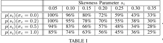
Figure 1 shows an example which demonstrates the con-nection between reflection symmetry identification and shape orientation considered in this work. In Fig. 1 (a), the axes of reflection symmetry for a symmetric pattern of order 6 are sketched. For the same pattern, the optimal axes are shown in Fig. 1 (b). It can be observed that the set of axes in Fig. 1 (b) is a subset of the reflection symmetry directions in Fig. 1 (a). For the rotationally symmetric shape of Fig. 1 (c), reflection symmetry does not exist, nevertheless optimal axes may well be defined.
[image:2.612.329.544.416.496.2](a) (b) (c)
Fig. 1. Identification of reflection symmetry and detection of optimal axes. (a): 6 lines indicate the reflection symmetry directions. (b), (c): 6 half-lines define the optimal axes.
C. Geometric and complex moments
TheGeometricandComplexmoments, that will be used in
the analysis, are defined in this section:
Definition 4. The geometric central moments of an image
I are defined as:
µpq=
Z
x
Z
y
(x−µ10)p(y−µ01)qI(x, y)dydx (II.8)
whereµpq=
R
x
R
yxpyqI(x, y)dydx. In the remaining of this paper, we will assume that the pattern’s centroid is used as the origin of the coordinate system and consequently µpq ≡
µpq. Of particular interest in this work is the moment-based objective function obtained by rotating I by δ∈ [0,2π] and evaluatingµpq as follows:
Mpq(δ) =
Z
x
Z
y
A change of variables yields:
Mpq(δ) =
Z
x
Z
y
dx(δ)pdy(δ)qI(x, y)dydx (II.10)
where ·
dx(δ)
dy(δ)
¸
=
·
xcosδ−ysinδ xsinδ+ycosδ
¸
(II.11)
The function Mpq is said to be degenerate, if Mpq(δ) = constant, ∀δ ∈ [0,2π). Assuming K samples of I, we may estimate (II.10) as follows:
f
Mpq(δ) = K
X
i=1 dxi
p(δ)d yi
q(δ)I(x
i, yi) (II.12)
Definition 5.The complex moments of an imageIare defined in the polar domain as:
cpq=
Z ∞
r=0
Z 2π
θ=0
rp+1ejqθI(r, θ)dθdr (II.13)
We estimate (II.13) as follows:
e
cpq= K
X
i=1
rpi+1ejqθiI(r
i, θi) (II.14)
III. MOMENT-BASED SHAPE ORIENTATION:A BRIEF REVIEW
In this section, the main results of [2], [4],[5],[6],[14] are summarized, constituting the basis of our work. For most irregular patterns (including patterns with a single axis of re-flection symmetry and2−fold rotationally symmetric shapes), orientation can be naturally derived from the direction of the pattern’s axis of elongation. The principal axis method [5] estimates this direction by seeking the minima of the second-order moment-based function M02. It can be shown that if M02 is non-degenerate, the minimization problem has
two solutions, namely φpa and φpa +π. Note that with the exception of 2−fold rotationally symmetric shapes, the set {φpa, φpa+π}, provides a sub-optimal solution to the orientation problem, since the second property of Def. 3 is not satisfied.
Forn−fold (n >2) rotationally symmetric shapes, it can be proved thatM02is degenerate [4], [6]. More specifically, it was shown that the moment functionM0N will be non-degenerate only if N ≥ n. In this case, minimizing M0n yields n
generalized principal axissolutions uniformly distributed over
[0,2π), namelyφgpaλ =φgpa+ 2(λ−1)π/n, λ= 1, . . . , n. It can be seen that the set{φgpaλ }provides an optimal solution to the shape orientation problem, by associating each fold with a unique half line. It was additionally shown in [6], that in the case that nis odd, the set {φgpaλ } will not coincide with the directions of reflection symmetry if those exist. The authors showed that, in this case, minimizing M0N withN > neven is likely to provide a solution to this problem.
In addition to geometric moments, complex moments have also been employed as useful features to define the orientation of symmetric patterns. The authors in [10] showed that for ann−fold rotationally symmetric shape the complex moment
cq−1q will be non-zero only ifq is an integer multiple of the
fold number, that isq=sn, s∈ N∗1. Ifq
min is the smallest integer such that cq−1q 6= 0 and φupa = ∠cqmin−1qmin, the
universal principal axes [14] are defined as φupaλ = (φupa+
2(λ −1)π)/qmin, λ = 1, . . . , qmin. Note that the set of {φupaλ }is optimal only if qmin =n.
The framework given in [2] is a generalization of the univer-sal principal axes method and is considered state-of-the-art in moment-based shape orientation and symmetry classification. First, a method for the automatic selection of the order p
is presented in [2]. Then, it is shown that classification of both rotational and reflection symmetry can be performed by considering all non-zero complex momentscpqi, i= 1,2, . . ..
The phase of each non-zero generalized complex moment
φgcmi = ∠cpqi is used to define a set of directions φ
gcm i,λ =
(φgcmi +(λ−1)π)/qi, λ= 1, . . . , qi. The reflection symmetry axes are obtained from the intersection of the axis sets{φgcmi,λ }. Additionally, the fold number is estimated as the biggest common factor of the orders qi. Optimal axes are obtained by solving a simple linear programming problem.
IV. AUNIFYING FRAMEWORK FOR SHAPE ORIENTATION
In this section, a novel methodology is presented that extends previous work on geometric moment-based functions and attempts to unify most of the results of the methods described above in a single framework and perspective.
Two modifications to the geometric moment-based approach presented in [4] are introduced. Firstly, an one-to-one mapping
f :R → R which operates on the distance r of each point from the origin is introduced:
f(r) =f³px2+y2´=f
µq
dx2(δ) +dy2(δ)
(IV.1)
It should be noted that the above mapping does not modify the angle distributionθ. Then, a modified moment-based function
Wpq can be defined, as follows:
Wpq(δ) =
Z
x
Z
y {f
µq
dx2(δ) +dy2(δ)
dxp(δ)dyq(δ)I(x, y)dydx} (IV.2)
Since f is an one-to-one function and operates only on r, inferring symmetry from eitherMpq orWpq is equivalent.
Secondly, moment-based functions of order p+q larger than n are examined. Such an attempt was also made in [6]; however, the presented approach neither guarantees the detection of possible reflection symmetry axes nor provides a closed-form solution. In general, optimizingWpqfor arbitrary
p, q does not result in reflection symmetry identification [6]. Nevertheless, the orders p, q can be selected such that Wpq satisfies a reflection symmetry criterion. Indeed, if we set
p = N1 = 2i1+ 1, q = N2 = 2i2+ 1, where i1, i2 ∈ N, then for a reflection symmetric pattern of order n, WN1N2
will necessarily have at least 2n zero-crossing points equally spaced over the interval [0,2π). The estimated zero-crossing points in this case will indicate the reflection symmetry directions.
In the remaining of this section, an analysis of the functions
WN1N2 based on Fourier series decomposition is introduced.
Using the proposed formulation all symmetry information (fold number estimation, axes of reflection symmetry/optimal axes for shape orientation and type of symmetry) can be extracted from WN1N2, and via straightforward mathematical
manipulations, one can employ solely closed-form solutions and formulas to tackle these tasks. Proposition 1 provides a way to estimate the order of symmetry. Proposition 2 is related to the proper selection of the orders N1 and N2. Finally, proposition 3 proposes a method to estimate the possible axes of reflection symmetry and identify the type of symmetry.
Proposition 1. Let WN1N2 be a non-degenerate moment-based function derived from a rotationally symmetric pattern
of ordernand letcWN1N2(l),l= 1,2, . . ., be the
correspond-ing Fourier series coefficients. Then,ncan be estimated as the
frequency bin of the first-non zero coefficient, or alternatively, as the biggest common factor of the bins corresponding to all non-zero coefficients.
The above proposition proposes a viable method to estimate the fold numbernof rotationally symmetric patterns from the Fourier expansion of the non-degenerate geometric moment-based function WN1N2(for a proof of this proposition, please
see Appendix A). Proposition 1 bares in mind the fold number estimation principles suggested in [2],[14].
Assume now that we are given K =mn samples of I in polar coordinates as follows:
I(rk, θkλ), κ= 1, . . . , m, λ= 1, . . . , n (IV.3)
where m is the total number of points in one fold. Let p, q
be non-negative integers such that pmax=N12−1 andqmax= N2−1
2 . Let also, for a fixed s = ln, l ∈ N∗, ps,i, qs,i be
the integers which satisfy the conditions 2(p−q) = sn or
2(p+q+ 1) =sn. Finally, we denote g the function g(r) =
f(r)rN1+N2. Then, it can be shown (see Appendix B) that
the Fourier series expansionWcN1N2(s)of the non-degenerate
moment-based function WN1N2 is given by: c
WN1N2(s) = πe
jπ/2{B
N1N2(s)
m
X
κ=1
I(rk, θκ1)g(rκ)ejsnθκ1},s=ln
(IV.4)
where BN1,N2(s) = P
i(−1)qs,iA(N12−1, ps,i)A(N22−1, qs,i)
and A(a, b) is a weighting coefficient depending solely on
a, b.
In the case that N1+N2< n, a slightly modified version of the theorem given in [4], [6] can be proposed (for proof see Appendix C), as follows:
Proposition 2. Let WN1N2 be a moment-based function
derived from a rotationally symmetric pattern of order n. In
the case thatN1+N2< n, thenWN1N2 will be degenerate .
For N1 +N2 > n, WN1N2 will be degenerate only in
the case that {BN1N2(s)}
smax
s=1 = 0, wheresmax = b(N1+
N2)/nc. Nonetheless, a thorough investigation of this scenario is out of the scope of this work.
Summarizing the results of this section so far, we have provided a methodology to estimate the order of symmetry
through the Fourier series expansion of geometric moment-based functions of appropriate order. Analytical expressions for the Fourier coefficients are provided by (IV.4). Next, the focus is on reflection symmetry identification. This problem is closely related to the determination of the zero-crossing points of the cosine terms defined by cWN1N2(s) in (IV.4).
To tackle this task, WN1N2 is expressed as the superposition
of the cosine terms (Fourier series) defined byWcN1N2(s), as
follows:
WN1N2(δ) =
sXmax
s=1
2|WcN1N2(s)|cos[snδ+∠WcN1N2(s)]
(IV.5) We also denote ΞN1N2(s, δ) = 2|WcN1N2(s)|cos[snδ +
∠cWN1N2(s)] and ξ(s, δ) = ΞN1N2(s, δ)/πBN1N2(s). The
zero-crossing points ofΞN1N2(s,; ) andξ(s,; ) are given by:
zs,λ = π/2−∠
c
WN1N2(s) + (λ−1)π
sn ,
= π−∠wb(s) + (λ−1)π
sn , λ= 1, . . . ,2sn
(IV.6)
wherewb(s)is defined as the normalized Fourier coefficient:
b
w(s) = WcN1N2(s) πe−jπ/2B
N1N2(s)
=
m
X
κ=1
I(rk, θκ1)g(rκ)ejsnθκ1
(IV.7) Proposition 3. Let WcN1N2(s),s = 1,2, . . . be the non-zero Fourier Coefficients of the moment-based functions
WN1N2withN1= 2i1+1,N2= 2i2+1,i1, i2∈ N, computed from a reflection symmetric pattern of order n. Then, the cosine
terms defined from cWN1N2(s),ΞN1N2(s,; ) and WN1N2 will
necessarily have the same subset of 2nzero-crossing points.
Thus, reflection symmetry can be derived from the identi-fication of the subset{zi} in{zs,λ}(for proof of Proposition 3, see Appendix D). More specifically, the axes of reflection symmetry will be included in the set of directions:
αs,λ = π
sn−zs,λ
= ∠wb(s)−(λ−1)π
sn , λ= 1, . . . , sn (IV.8)
In addition, the observation that WN1N2 will necessarily
include the same subset of a total of2nzeros independently of the order selection (see Appendix D) is not valid for n−fold rotationally symmetric patterns with no reflection symmetry. Therefore, considering the derived Fourier series expansion of
WN1N2 enables us to apply the reflection symmetry
identifi-cation principle, suggested in [2], in the proposed framework. Similarly to [14], if |wb(1)| 6= 0, a set of optimal axes can be defined as:
φoaλ =
∠wb(1)−2(λ−1)π
sn , λ= 1, . . . , n (IV.9)
In the rare case that|wb(1)|vanishes, then optimal axes can be obtained by solving the linear programming problem given in [2].
to the computation of the normalized Fourier coefficientwb(s). This establishes a more clear connection of the proposed approach with the methods given in [2],[14]. It should be noted that wb(s)is computed using only the points contained in one fold of the pattern2. Knowledge of the number of points in one fold implicitly assumes knowledge of the fold number. This dependency can be alleviated by averaging over all points as follows:
b
wav(s) = K
X
i=1
I(ri, θi)g(ri)ejsnθi,s= 1,2, . . . (IV.10)
Let us now consider the term:
b
q(l) =
K
X
i=1
I(ri, θi)g(ri)ejlθi,l= 1,2, . . . (IV.11)
Clearly, for l=sn, the termbq(l)≡wbav(s). Now for l6=sn, using the methodology presented in [10], it can be shown that
b
q(l) = 0. Thus, evaluating qb(l), l = 1,2, . . . and finding
b
q(l)6= 0is equivalent to computing the Fourier transform of all non-degenerate moment-based functions and picking the non-zero normalized Fourier coefficients wbav(s) in one step. Finally, it can be observed that, in the special case where
g(r) = rl and g(r) = rp+1, we obtain bq(l) ≡ ec
l−1l and
b
q(l)≡ecpl respectively. Thus, the methods in [14] and [2] can be derived as special cases of the general approach presented in the section.
V. ROBUST FEATURE SELECTION IN THE POLAR FREQUENCY DOMAIN
An important conclusion that can be drawn from the analy-sis presented in the previous section is that the performance of moment-based shape orientation largely depends on a feature set where the difference between the zero and non-zero coefficients is emphasized as much as possible. It should also be noted that the same feature set can be additionally used for further pattern analysis tasks, such as classification. Thus, the aim of this section is to introduce a robust moment-based feature extraction methodology for symmetric patterns, that can be used for several pattern analysis tasks.
In general, moments are global features that appear to be quite insensitive to uniform distortions of the symmetric pattern. In the context of shape orientation and complex moments, this was experimentally verified in [12], where the boundaries of shapes were contaminated by Gaussian noise. Nevertheless, the accurate computation of the moment-based feature set and consequently the identification of non-zero coefficients in a stable and robust manner strongly depends on the accurate computation of the shape centroid. Inaccurate calculation of the symmetry center results in a non-uniform change of the angular distributionθ, thus rendering the values of zero and non-zero coefficients comparable. Errors in center estimation may be caused due to digitization errors,
non-uniform illumination conditions, poor segmentationorpartial
occlusion. Although the symmetric patterns are assumed to
2This result also establishes a connection of our approach with the method
discussed in [7].
be already segmented in this work, such distortion cases may well be encountered.
To alleviate the aforementioned problem of erroneous cen-troid estimation, the core of the approach is based on the computation of a feature set from the image Fourier domain. LetIb(k),k= [kx, ky]T ∈ R2be the2D Fourier transform of
I andM be the magnitude ofIb, that isM(k) =|Ib(k)|. The following lemmas are directly derived from the properties of the Fourier transform of symmetric images:
Lemma A. If I satisfies (II.1), then M will be also
rotationally symmetric of order n or 2n around the origin,
ifn is even or odd respectively.
Lemma B.IfIsatisfies(II.5),thenM will also be reflection
symmetric about the liney= tanαx.
Thus, (IV.11) in the image Fourier domain takes the form:
b
qM(l) =
X
kr,kθ
M(kr, kθ)g(kr)ejlkθ, l= 1,2, . . . (V.1)
where M(kr, kθ) is the polar representation of M. Lemmas A and B suggest that a feature set computed from the image Fourier domain may well be used for symmetry classification. Additionally, the computation of the features does not employ the estimation of the pattern’s centroid, due to the shift invariant property of the Fourier transform. In the remaining of this section, we provide a detailed description of the proposed method based on the above principles.
The proposed approach starts with computing a gray level edge mapGof the given imageI, which retains both magni-tude and phase information, as follows:
G=Gx+jGy (V.2)
where Gx = ∇xI and Gy = ∇yI are the gradients along the horizontal and vertical direction respectively. This step provides the location, magnitude and orientation of the image high-activity structures which can be used as salient features to characterize symmetry. Areas of constant intensity level also provide symmetry information, nevertheless such areas are very sensitive to possible uneven lighting conditions. At the same time, low spatial frequency components inherent to the low pass nature of images will be filtered out as well. For real images, in most cases, the contribution of low spatial frequencies rather shadows the existence of periodicity than facilitates the symmetry detection process. Additionally, it should be noted that a band-pass filtered version of the original image, as suggested by the use of practical differential operators, eliminates possible noise and aliasing effects [16].
The next step is to compute the Fourier transform ofG,Gb, and consider its magnitude solely. In this case, we have:
b
G(k) =jkxIb(k)−kyIb(k) (V.3) Thus, for the magnitudeMG we get:
MG(k) =
q
(k2
x+k2y)M(k) =krM(k) (V.4) which shows thatMG retains all the symmetric properties of
Equation (V.1) indicates the use of a polar representation. A traditional approach to obtain such a representation is to evaluate the Fourier Transform of the image over the Cartesian grid using the standard FFT and then interpolate the outcome over a polar grid. In general, this method is unstable and sensitive to interpolation errors due to possible image noise [17]. Additionally, in the context of moment-based orientation and matching, such an approach will be biased towards moments that are largely affected by the Cartesian structure of the original FFT. More specifically, moments of order multiple of two or four are expected to have relatively significant values regardless of the real order of symmetry. The last observations emphasize the importance of using a true polar Fourier representation. Therefore, in this work, we adopt a fast and accurate polar Fourier transform recently proposed in [15]. The method is algebraically stable while the algorithm’s computational complexity is on the order of the standard Cartesian FFT.
To improve the robustness of the proposed method, a noise reduction scheme is also employed, based on the classical sin-gular value decomposition (SVD) of the polar representation
M(kr, kθ)in a set of eigenimages [18]. More specifically, the magnitude of the polar Fourier transform M is decomposed to the following matrices:
M =U SVT = R
X
j=1
sjMj (V.5)
where the columns of U and V are the eigenvectors of the subspace spanned by the columns and rows ofM respectively and S is a diagonal matrix containing the corresponding eigenvalues. Mj = ujvTj is the jth eigenimage, sj is the corresponding eigenvalue andR is the rank ofM. Observing that {vj}R
j=1 is the subspace spanned by the rows ofM, the
following lemmas are given without proof:
Lemma C. Let M be the polar representation of a
ro-tationally symmetric image of order n and let Mj be the
correspondingjth eigenimage. Then, M
j will be rotationally
symmetric of order sn,s∈ N∗.
Lemma D. If M is reflection symmetric about a line y=
tanax, then Mj will also be reflection symmetric about the
same line.
Evaluating (V.1) using Mj only yields:
b
qMj(l) =
X
kr,kθ
Mj(kr, kθ)g(kr)ejlkθ
= X
kr
uj(kr)g(kr)
X
kθ
vj(kθ)ejlkθ, l= 1,2, . . .
(V.6)
The above equation suggests that the computation of the coef-ficients qbMj(l),l= 1, . . . simply reduces to the computation
of the DFT of vj(kθ).
In the context of this work, the scheme suggested above can be interpreted as follows. Firstly, the estimation of each eigen-vector combines all symmetry information provided by the rows of M. In contrast to simple averaging schemes [9],[19], where a periodic pattern is constructed by averaging the polar representation overr, the estimation in our case will be biased
towards the rows of M, that capture periodic components of large magnitude. This comes directly from the fact that SVD projects the input image on eigenimages that minimize the mean squared reconstruction error. This property is favorable since such components are likely to provide more robust estimations of the true periodicity. Secondly, it is suggested in [20] that SVD-based processing of an image results in noise filtering along the image vertical and horizontal lines. This is also a favorable property in our case, since symmetry is inferred solely from the rows ofM.
Elementary matrix approximation theory suggests that the best approximation Mf of the matrix M, in terms of mini-mizing the mean squared error and under the constraint that rank(Mf) = L, is given by reconstructing M using the L
most significant eigenvectors according to (V.5). In our case, we are not interested in optimal compact representations and, given theLmost important eigenvectors, we wish to estimate their fundamental frequency which is equal to the order of symmetry. Assuming that the image is corrupted by white noise isotropically distributed in all signal dimensions, the signal-to-noise ratio for the jth eigenvector will be equal to
sj/σ2, whereσ2 is the power of noise. In this case, the first eigenvector is guaranteed to be the least noisy periodic pattern achieving the highest signal-to-noise ratio. Any combination of eigenvectors will result in a more noisy periodic pattern and therefore in less reliable estimates of the pattern’s periodicity. For cluttered images (for example images where the sym-metric pattern is embedded in a complex background) which result in cluttered Fourier transforms, noise is not white and the above analysis does not hold. Assuming that there exists a range of values ofkr, such that the corresponding rows ofM are strong periodic patterns with dominant frequency equal to the order of symmetry, it is still expected that this periodicity will be captured by one of the most important eigenvectors. In particular, when the amount of clutter is not large, the periodic signal will be captured by the first eigenvector. Experimentation suggested that the remaining eigenvectors are noisy and therefore do not constitute a positive contribution to the order estimation process.
As the amount of distortion increases, there might be a case that the first eigenvector captures the effect of clutter (in most cases this is a pattern with strong very low frequency components) and the desired periodic pattern appears as one of the remaining eigenvectors. In this case, considering the first
L eigenvectors, as described in the algorithm given below, equips the proposed scheme with further robustness at the cost of additional computational complexity. Note that if the desired periodic pattern does not appear as one of the very first few most significant eigenvectors, then the assumption for the existence of a strong periodic pattern along the rows of theM probably does not hold and the method is likely to fail. Therefore, one should check only for small values ofL; however, we note that we have not devised an algorithm for the automatic selection of the exact number of the eigenvectors to be examined.
resolve the order ambiguity induced by the frequency domain formulation. If more than one eigenvectors are considered, the same method is employed to recover the true order of symmetry. In general, image registration methods can provide the basis of a brute force approach for symmetry detection, since we can always rotate the input image by 2π/l, l∈ N∗
and check if the original image and its rotated version can be registered successfully. Once the order has been identified, the center of symmetry can be estimated using the approach suggested in [3],[19]. The method is based on the observation that symmetric images of order n, when rotated by 2π/n, are related to each other by a pure translation. Once the translation is recovered, a simple geometric inspection reveals that both the distance and the direction of the center of symmetry with respect to the image center can be easily computed. Finally, the frequency domain formulation also induces a further ambiguity when the pattern’s orientation axes are to be computed, as described in the last step of our algorithm. To resolve the problem, an additional moment feature computed from the image spatial domain is used. The same feature is also used to classify the pattern as rotationally or reflection symmetric. We note that, at this point, both the symmetry order and center are available, and therefore the particular feature can be computed with good accuracy.
Frequency domain moment-based symmetry detection
algorithm
Inputs: The image I, the number L of eigenvectors to be considered and the value of a threshold ². I(δ) is the image obtained from the input image after rotation by δ. Step 1. Using any image registration technique [21], check if the registration process between the input image I and its rotated version I(π) provides a valid solution. If this is the case, then the order of symmetry is even, otherwise it is odd. Step 2. Compute the polar Fourier representation of the complex gradient edge map G, and keep its magnitude
M(kr, kθ). Perform3 the SVD of M and keep the L most important eigenvectors vj(kθ), j= 1, . . . L.
Step 3. Compute bvj(l) = DFT{vj(kθ)}. Obtain a set of possible solutions n0
j = arglmax|vbj(l)|, j = 1, . . . L. Set
nj ← n0j or nj ← n0j/2, if n is even or odd respectively. Recover the true order of symmetry n by checking if
I(2π/nj)can be registered withI. Denotevnthe eigenvector which corresponds to the correct solution.
Step 4. For the correct solution of Step 3, use the approach suggested in [3],[19], to estimate the center of symmetry. Step 5.Use the phase∠bvn(n0)to obtain a set of n0 direction angles φa
λ, λ= 1, . . . , n0 according to (IV.9). Note that if n is odd, a total of 2n solutions is obtained, since n0 = 2n.
In this case, denote {φa,λ1}, λ odd and {φa,λ2}, λeven the two possible subsets. Compute the phase ∠wav(n) from the image spatial domain according to (IV.10) and obtain a set of
n direction anglesφb
λ, λ= 1, . . . , n. Compute the difference
∆ = |φa
λ−φbλ| if n is even and similarly∆1 =|φa,λ1−φbλ| and ∆2 = |φλa,2 −φbλ| if n is odd. Define the pattern’s
3each row of M is normalized to zero mean to remove the local DC bias.
orientation from the set {φa} if n is even and from the subset{φa,k}, wherek= arg
imin ∆i, ifnis odd. Finally, if
∆< ²and similarly∆k < ², classify the pattern as reflection symmetric.
For the image registration method used in our scheme, we suggest the use of fast FFT-based correlation schemes [16]. The values of L and² should be adjusted depending on the application. Note that the very last step of the algorithm can be modified such that no threshold selection is employed at the cost of additional computational complexity. This can be done by computing a reflected version of the input image about any of the axes which define the pattern’s orientation. Then, one needs to check if the original image and its reflected version can be registered successfully.
VI. RESULTS
The main target of this section is to draw a comparison between Shen’s complex moment formulation which operates on the image spatial domain [2] and the frequency domain moment-based approach proposed in section V. For this purpose we have considered more than 150 patterns taken from two different databases used in [3] and in [2],[12]. A representative sample of the images used is shown in Fig. 2. The section is organized in a way such that performance is assessed for progressively increased shape distortions and more challenging situations.
A. A study of the effect of erroneous symmetry center estima-tion
In this part of the experimental section, we study the performance of moment-based symmetry detection methods in the case where no shape distortion exists, but the shape centroid is artificially displaced. Let us first denote by{F}any moment-based feature set computed from a symmetric pattern of order n, that is{F}={cpq},{qb},{qbM} or {bv1}. We also write{F}={Fnz} ∪ {Fz}, where{Fnz}and{Fz}is the set of the expected non-zero and zero coefficients respectively4. For example, given a 5−fold rotationally symmetric pattern, the set{Fnz}includes the moment features which correspond to moment orders multiples of 5, while all the remaining moments are gathered in the set{Fz}.
For each tested pattern, we assume that the symmetry order is known. Given that the total energy of {F} is normalized to one, that is Pi=1|Fi|2 = 1, the evaluation is based on
computing the following metric:
R=X
nz
|Fnz|2 (VI.1)
The above simple metric can be used to measure the effect caused by deviations from perfect symmetry on the various moment-based symmetry detection methods. For example, for perfect symmetries, it is expected that the set{Fz} contains negligible values and therefore R ' 1. As the amount of symmetry distortion increases, the moments included in the
(a) (b) (c) (d) (e)
Fig. 2. A sample of the patterns used in our experiments taken from the database used in [3].
set{Fz}will no longer be zero, and therefore the value of R
is expected to decrease. The amount of decrease reflects the robustness of each method in relation to the type of symmetry distortion.
We study the performance of Shen’s method [2] which operates on the image spatial domain and therefore it is affected by the erroneous symmetry center estimation. We have examined displacements ∆r from the real symmetry center of size up to 3 pixels. More specifically, for a fixed
∆r, we define∆x= ∆rcos(γ) and∆y = ∆rsin(γ), where
γ is uniformly distributed over [0,2π]. We then compute a polar representation of the image using c0
x(∆r, γ) =cx+ ∆x and c0
y(∆r, γ) = cy + ∆y, where cx, cy are the standard estimates of the pattern’s centroid coordinates. Finally, we compute R(∆r) = (1/Nγ)
P
γR(∆r, γ), where Nγ is the number of angles used.
The method in [2] is compared with the proposed frequency domain moment-based scheme with L = 1 which does not employ any centroid estimation. Figure 3 shows a qualitative comparison of the two methods by plotting the distribution of the ratio R(∆r), for ∆r ={1,2,3} in the same histogram. The width of each histogram bin is0.1units, while its center is indicated by the numbering of the x−axis in each plot. It can be seen that the performance of the method in [2] rapidly deteriorates with respect to increasing values of ∆r.
B. Classification accuracy for the case of local distortions and noise
The main purpose of this section is to draw a comparison between the performance of Shen’s method and that of the proposed scheme in the presence of controlled local distortions and noise. To generate the corrupted test images, we have used a linear degradation model [5]:
Ic= (1−WG)I+n (VI.2)
where I and Ic is the original and the corrupted image respectively. The image I is assumed to be normalized in the range [0,1], while the image domain is supposed to be [-1/2, 1/2]x[-1/2, 1/2]. WG=e−|x−xc|
2/2σ2
c is a2D Gaussian
function of standard deviation σc centered at the pointxc =
[xc, yc]T of the image plane, while n is zero mean white Gaussian noise.
The term1−WG models local shape distortions controlled by the parameter σc. For small values of σc, very local and relatively abrupt changes of the image intensity values around the pointxcare modeled. Asσcincreases, the number of pixels
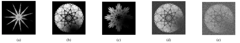
affected also increases but the change in the intensity values becomes smoother. Fig. 4 (a),(b) and (c) shows three corrupted images for three representative values ofσc = 0.2,0.5and1 respectively. It can be observed that the term1−WG attempts to model the effect of inefficient image segmentation.
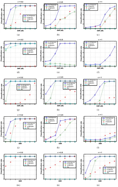
Since the effect of the local distortion model will be generally different for each pattern, we have chosen a set of 5 representative shapes (shown in Fig. 2 (a)-(e)) of various symmetry orders and we present classification results for each pattern separately. Figures 2 (a),(d) and (e) illustrate examples of doughnut-like, disk-like and garland-like symmetric pat-terns. Figure 2 (b) shows a radial shape, while the pattern in Fig. 2 (c) represents more typical examples of symmetry. For each pattern, a set of test images is generated as follows. Given a fixed value ofσcand signal-to-noise ratio (SNR), a point on the pattern’s boundary is randomly selected and used as the center ofWG. Boundary points are considered solely, since the outer part of the shape is more likely to be corrupted by local distortions such as segmentation errors. The term(1−WG)I is computed and then white Gaussian noise of fixed power is added to the result to obtain Ic. The power of noise is calculated according to the given SNR value and the energy of the original imageI. Finally, for eachσc and SNR, to assure the validity of the classification results, a total of 100 test images is generated. We have considered σc= 0.2,0.5and1 and SNRs in the range[−6,12]dBs (see Fig. 4 (d) and (f) for an example).
Classification results are presented for 4 different cases. The first is the proposed scheme based on the first eigen-vector solely. The classification is said to be correct if the symmetry order is given by arglmax|bv1(l)|. The second is the proposed scheme based on the combination of the first and second eigenvectors. In this case, the classification is said to be correct if any of n0
j = arglmax|bvj(l)|, j = 1,2
coincides with the expected symmetry order. The third is a simple averaging scheme suggested as part of the works in [9],[19]. More specifically, we replace SVD with averaging over kr, that is we compute a(kθ) =
P
krM(kr, kθ) and
its spectrum ba=DFT(a). Similarly, the pattern is classified correctly if the order of symmetry is arglmax|ba(l)|. Since two possible solutions are examined by our combined scheme, we also consider the second largest peak for a more balanced comparison. Finally, in a similar spirit, the performance of Shen’s method is evaluated.
0.1 0.2 0.3 0.4 0.5 0.6 0.7 0.8 0.9 1 0
20 40 60 80 100 120 140 160
R
Number of patterns
Proposed method
Shen with Dr = 1
(a)
0.1 0.2 0.3 0.4 0.5 0.6 0.7 0.8 0.9 1 0
20 40 60 80 100 120 140 160
R
Number of patterns
Proposed method
Shen with Dr = 2
(b)
0.1 0.2 0.3 0.4 0.5 0.6 0.7 0.8 0.9 1 0
20 40 60 80 100 120 140 160
R
Number of patterns
Proposed method
Shen with Dr = 3
[image:9.612.87.523.57.181.2](c)
Fig. 3. (a)-(c): The distributions ofR(1),R(2)andR(3)respectively plotted together with the distribution ofRevaluated with our method. Blue colour: proposed method, red colour: Shen’s method [2].
(a) (b) (c) (d) (e)
Fig. 4. (a)-(c): An example of locally distorted patterns forσc = 0.2,0.5and1respectively. (d)-(f): The pattern in Fig. 4 (b) for SNR=12 and 0 dB respectively.
robustness of the proposed combined scheme is evident. For
σc= 0.2and for SNR as low as -3 dB, the classification rate is higher than 0.8 for all patterns. For σc = 0.5 and SNR = 3 dB, the method achieves a minimum classification rate of 0.9. Good performance for most patterns is achieved for SNR in the range[3,12]dB andσc= 1, with the exception of the fourth pattern (Fig. 5 (l)) where the method fails. With few exceptions, the scheme based on the first eigenvector solely, outperforms the rest of the methods examined. A characteristic case where the scheme fails is for the second pattern and
σc= 0.5(Fig. 5 (e)). It can be observed that using the second eigenvector, in this case, is highly beneficial. The scheme based on averaging is, in general, unstable. For the first and fifth pattern, the method achieves relatively good performance, while for the second and third pattern, the classification rate is very low for all values of σc. The method in [2] fails badly for the majority of the cases examined. Finally, the proposed scheme was also tested for the case of the first three eigenvectors. The gain in performance was not significant (for example, the method still fails for the the fourth pattern and
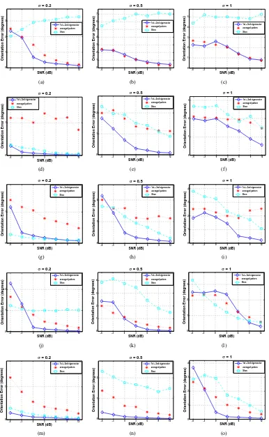
σc= 1). For simplicity, the obtained results are omitted. In addition to classification accuracy, Fig. 6 shows the mean value of the orientation error in degrees defined as
e=|φ1−φ01|, where {φλ}and{φ0λ} is the set of orientation axes computed from the noisy and noise-free versions of each pattern respectively. It can be observed that, in most cases, the proposed scheme achieves the smallest error.
C. Experiments with real images
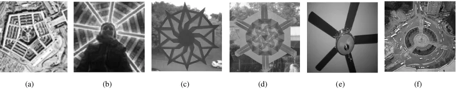
The last part of the experimental section illustrates some examples where the proposed scheme is used to detect symme-tries in real images. The patterns depicted in Fig. 7 (a),(c),(d)
and (f) are cases of non-perfect symmetries embedded in a complex background. Figure 7 (b) shows an example of partial occlusion, while Fig. 7 (e) gives an example of symmetry distorted by projective distortion. In general, moment-based methods which operate in the image spatial domain are unable to handle such cases, since they are not robust.
For simplicity, we do not assess the effectiveness of the image registration method employed in our scheme. The algorithm was able to detect the correct order of symmetry for the first five patterns. The true order was recovered from the spectrum of the first eigenvector, with the exception of Fig. 7 (c), where the correct solution was provided by the additional use of the second eigenvector. For each case, the spectrum of the extracted periodic pattern is shown in Fig. 8. Depending on the type of symmetry, Fig. 9 shows the estimated axes of orientation and reflection symmetry.
For the last pattern in Fig. 7 (f), a visual inspection reveals that the true order of symmetry is 3. However, it can be observed that only a very small number of image features indicate the existence of symmetry and, therefore, global schemes, such as the one presented in this work, are likely to fail.
[image:9.612.60.554.224.313.2]−6 −3 0 3 6 9 12 0 0.2 0.4 0.6 0.8 1 SNR (dB) Classification rate
σ = 0.2
1st + 2nd eigenvector
1st eigenvector
averaged pattern
Shen
(a)
−6 −3 0 3 6 9 12 0 0.2 0.4 0.6 0.8 1 SNR (dB) Classification rate
σ = 0.5 1st + 2nd eigenvector 1st eigenvector averaged pattern Shen
(b)
−6 −3 0 3 6 9 12
0 0.2 0.4 0.6 0.8 1 SNR (dB) Classification rate
σ = 1
1st + 2nd eigenvector
1st eigenvector
averaged pattern
Shen
(c)
−6 −3 0 3 6 9 12
0 0.2 0.4 0.6 0.8 1 SNR (dB) Classification rate
σ = 0.2
1st + 2nd eigenvector 1st eigenvector
averaged pattern
Shen
(d)
−6 −3 0 3 6 9 12
0 0.2 0.4 0.6 0.8 1 SNR (dB) Classification rate
σ = 0.5
1st + 2nd eigenvector
1st eigenvector
averaged pattern
Shen
(e)
−6 −3 0 3 6 9 12
0 0.2 0.4 0.6 0.8 1 SNR (dB) Classification rate
σ = 1
1st + 2nd eigenvector
1st eigenvector
averaged pattern
Shen
(f)
−6 −3 0 3 6 9 12 0 0.2 0.4 0.6 0.8 1 SNR (dB) Classification rate
σ = 0.2
1st + 2nd eigenvector 1st eigenvector averaged pattern Shen
(g)
−6 −3 0 3 6 9 12
0 0.2 0.4 0.6 0.8 1 SNR (dB) Classification rate
σ = 0.5
1st + 2nd eigenvector
1st eigenvector
averaged pattern
Shen
(h)
−6 −3 0 3 6 9 12 0 0.2 0.4 0.6 0.8 1 SNR (dB) Classification rate
σ = 1 1st + 2nd eigenvector 1st eigenvector averaged pattern Shen
(i)
−6 −3 0 3 6 9 12 0 0.2 0.4 0.6 0.8 1 SNR Classification rate
σ = 0.2
1st+2nd eigenvector 1st eigenvector averaged pattern Shen
(j)
−6 −3 0 3 6 9 12
0 0.2 0.4 0.6 0.8 1 SNR Classification rate
σ = 0.5
1st+2nd eigenvector
1st eigenvector
averaged pattern
Shen
(k)
−6 −3 0 3 6 9 12
0 0.2 0.4 0.6 0.8 1 SNR Classification rate
σ = 1
1st+2nd eigenvector
1st eigenvector
averaged pattern
Shen
(l)
−6 −3 0 3 6 9 12 0 0.2 0.4 0.6 0.8 1 SNR Classification rate
σ = 0.2
1st+2nd eigenvector 1st eigenvector averaged pattern Shen
(m)
−6 −3 0 3 6 9 12 0 0.2 0.4 0.6 0.8 1 SNR Classification rate
σ = 0.5
1st+2nd eigenvector 1st eigenvector averaged pattern Shen
(n)
−6 −3 0 3 6 9 12 0 0.2 0.4 0.6 0.8 1 SNR Classification rate
σ = 1
1st+2nd eigenvector 1st eigenvector averaged pattern Shen
(o)
[image:10.612.109.505.72.700.2]−6 −3 0 3 6 9 12 0
1 2 3
SNR (dB)
Orientation Error (degrees)
σ = 0.2
1st + 2nd eigenvector
averaged pattern
Shen
(a)
−6 −3 0 3 6 9 12
0 1 2 3 4 5 6 7
SNR (dB)
Orientation Error (degrees)
σ = 0.5
1st + 2nd eigenvector
averaged pattern
Shen
(b)
−6 −3 0 3 6 9 12
0 1 2 3 4 5
SNR (dB)
Orientation Error (degrees)
σ = 1
1st + 2nd eigenvector
averaged pattern
Shen
(c)
−6 −3 0 3 6 9 12 0
1
SNR (dB)
Orientation Error (degrees)
σ = 0.2 1st + 2nd eigenvector averaged pattern Shen
(d)
−6 −3 0 3 6 9 12
0 1 2
SNR (dB)
Orientation Error (degrees)
σ = 0.5
1st + 2nd eigenvector
averaged pattern
Shen
(e)
−6 −3 0 3 6 9 12
0 1 2 3
SNR (dB)
Orientation Error (degrees)
σ = 1
1st + 2nd eigenvector
averaged pattern
Shen
(f)
−6 −3 0 3 6 9 12
0 1
SNR (dB)
Orientation Error (degrees)
σ = 0.2
1st + 2nd eigenvector
averaged pattern
Shen
(g)
−6 −3 0 3 6 9 12
0 1 2
SNR (dB)
Orientation Error (degrees)
σ = 0.5
1st + 2nd eigenvector
averaged pattern
Shen
(h)
−6 −3 0 3 6 9 12
0 1 2 3 4
SNR (dB)
Orientation Error (degrees)
σ = 1
1st + 2nd eigenvector
averaged pattern
Shen
(i)
−6 −3 0 3 6 9 12
0 1 2
SNR (dB)
Orientation Error (degrees)
σ = 0.2
1st + 2nd eigenvector
averaged pattern
Shen
(j)
−6 −3 0 3 6 9 12
0 1 2 3 4
SNR (dB)
Orientation Error (degrees)
σ = 0.5
1st + 2nd eigenvector
averaged pattern
Shen
(k)
−6 −3 0 3 6 9 12
0 1 2 3
SNR (dB)
Orientation Error (degrees)
σ = 1
1st + 2nd eigenvector
averaged pattern
Shen
(l)
−6 −3 0 3 6 9 12
0 1
SNR (dB)
Orientation Error (degrees)
σ = 0.2
1st + 2nd eigenvector
averaged pattern
Shen
(m)
−6 −3 0 3 6 9 12 0
1 2
SNR (dB)
Orientation Error (degrees)
σ = 0.5
1st + 2nd eigenvector averaged pattern Shen
(n)
−6 −3 0 3 6 9 12
0 1 2 3 4
SNR (dB)
Orientation Error (degrees)
σ = 1
1st + 2nd eigenvector
averaged pattern
Shen
(o)
[image:11.612.114.500.71.698.2](a) (b) (c) (d) (e) (f)
Fig. 7. The real images used in our experiments. The proposed method was able to detect the correct order of symmetry for the first five patterns (see Fig. 8). The orientation axes for each pattern are sketched in Fig. 9. The symmetric image in Fig. 7 (f) contains only a very small number of features indicating the existence of symmetry and, therefore, global schemes, such as the one presented in this work, are likely to fail.
0 5 10 15 20 25 30
0 0.05 0.1 0.15 0.2 0.25 0.3 0.35 0.4 0.45 0.5
Frequency bins
b v1
(a)
0 5 10 15 20 25 30
0 0.05 0.1 0.15 0.2 0.25 0.3 0.35 0.4
Frequency bins
b v1
(b)
0 5 10 15 20 25 30
0 0.1 0.2 0.3 0.4 0.5 0.6 0.7
Frequency bins
b v2
(c)
0 5 10 15 20 25 30
0 0.1 0.2 0.3 0.4 0.5 0.6 0.7
Frequency bins
b v1
(d)
0 5 10 15 20 25 30
0 0.05 0.1 0.15 0.2 0.25 0.3 0.35 0.4 0.45 0.5
Frequency bins
b v1
(e)
Fig. 8. The Fourier spectrum of the extracted periodic pattern using the proposed scheme for the symmetric images shown in Fig. 7 (a)-(e). Up to a factor of two, the order of symmetry is estimated asn0
j= arglmax|bvj(l)|. By checkingn0jandn0j/2, the true order is recovered.
[image:12.612.82.535.57.147.2](a) (b) (c) (d) (e)
Fig. 9. The orientation axes obtained using the proposed scheme for the first five patterns shown in Fig. 7.
obtained by applying an affine transform to the image shown in Fig. 7 (c). For each case, the affine transformed imageIAis related to the originalI according to the following equation:
IA(x) =I(Ax) (VI.3) whereA=
·
1 s
0 1
¸
andsis the skew parameter. The values of s used were 0.1, 0.2 and 0.35. Assincreases the induced orientation that the pattern exhibits is more evident and the deviation from rotational symmetry becomes more significant. The algorithm was able to detect the real order of symmetry for the first two cases for which the obtained orientation axes are sketched in Fig. 10 (d) and (e). Fors= 0.35, the examination of the spectrum of the extracted periodic pattern (for simplicity not shown here) revealed that the peak indicating the correct order of symmetry was largely attenuated and the dominant peak was located at the frequency equal to two. This is well justified since a careful examination of Fig. 10 (c) shows that the image depicts a well-oriented 2−fold rotationally symmetric pattern. The pattern’s orientation axes, in this case, are sketched in Fig. 10 (e).
Table I summarizes the results obtained by applying a range of affine distortions to the synthetic patterns taken
from [3] and [2]. The skewness parameter was varied in the range [0.05,0.35] with step equal to 0.05. The percentage of patterns for which the method was able to identify the order of symmetry correctly for s ≤ si is defined as p(si). The performance of the proposed scheme was evaluated for two different scenarios: affine transformations solely (σc =
0) and affine transformations plus local distortions (σc =
0.2,0.5 and1). In the noise-free case and for a considerable amount of affine distortionsi= 0.2, 72% of the tested patterns were classified correctly. For the same affine distortion and
σc= 1, the classification rate decreased by 16%. Much better performance was observed for moderate amount of affine and local distortions. For example, forsi= 0.1andσc = 0.5, the algorithm detected the real order of symmetry for the 83% of the total number of patterns considered.
[image:12.612.63.559.195.285.2] [image:12.612.78.541.331.437.2](a) (b) (c) (d) (e) (f)
Fig. 10. (a)-(c): The affine transformed images obtained from the image in Fig. 7 (c) usings= 0.1,0.2and0.35respectively. (d)-(f): The orientation axes obtained using the proposed scheme.
Skewness Parametersi
[image:13.612.78.538.57.145.2]0.05 0.10 0.15 0.20 0.25 0.30 0.35 p(si)(σc= 0.0) 100% 96% 80% 72% 59% 43% 33% p(si)(σc= 0.2) 100% 95% 78% 70% 55% 38% 30% p(si)(σc= 0.5) 94% 83% 66% 57% 48% 34% 28% p(si)(σc= 1.0) 85% 74% 63% 56% 45% 36% 25%
TABLE I
CLASSIFICATION RESULTS FOR THE CASE OF AFFINE TRANSFORMATIONS AND LOCAL DISTORTIONS.
do not adapt to these changes. Note that such phenomena were not taken into consideration for the results given in Table I.
VII. CONCLUSIONS
The problem of moment-based shape orientation and sym-metry classification was considered. In the first part of this work, we presented a study which attempts to unify many popular moment-based approaches in a single framework. In particular, we showed that results given from a complex moment formulation also apply to the case of appropri-ately defined geometric moment-based functions. Analytical expressions were derived based on Fourier series analysis. In the second part of this work, we presented a moment-based symmetry classification and matching algorithm which operates on the image Fourier domain and therefore does not require the accurate estimation of the symmetry center which is the main limitation of current approaches. Our formulation was based on a true polar Fourier representation of the extracted image gradients. Further robustness was achieved by using a periodicity estimation scheme based on subspace analysis. Simulation results demonstrated the efficiency of our approach.
VIII. ACKNOWLEDGEMENTS
The symmetric patterns used in our experiments were kindly provided by Prof. Michael Field and Prof. Shen. We thank Prof. Michael Elad for providing the Matlab implementation of the polar FFT. Finally, we would like to thank the anonymous reviewers whose suggestions and comments greatly improved the quality of this work. The work reported in this paper was funded by the Systems Engineering for Autonomous Systems (SEAS) Defence Technology Centre established by the UK Ministry of Defence.
APPENDIX
PROOFS OFPROPOSITIONS OFSECTIONIV
A. Proof of Proposition 1
From the very definition of rotational symmetry, we may observe that if the moment-based function WN1N2 is not
degenerate, then it will be periodic with period 2π/n. Let
c
WN1N2 be the Fourier series coefficients ofWN1N2:
c
WN1N2(l) =
1
2π
Z 2π
0
WN1N2(δ)e
−jlδdδ , l= 0,1,2. . . ,
Then, WcN1N2 will be non-zero only if l =sn, s∈ N
∗ and
potentially forl= 0. Therefore, the order of symmetry can be estimated as the frequency bin of the first-non zero coefficient, or more robustly, as the biggest common factor of the bins corresponding to all non-zero coefficients. ¤
B. Calculation of Fourier series expansion forWN1N2
Assume that we are givenK =mn samples ofI in polar coordinates as follows:
I(rk, θkλ), κ= 1, . . . , m, λ= 1, . . . , n
wheremis the total number of points in one fold. Additionally, we have:
dxi(δ) = xicosδ−yisinδ
≡ rκcosθκλcosδ−rκsinθκλsinδ
= rkcos[θκλ+δ]
where r = px2+y2 and θ = arctany/x 5. Similarly, we have dyi(δ) = rksin[θκλ+δ]. Therefore, WN1N2(δ) can be
expressed, as follows:
WN1N2(δ) =
K
X
i=1
f(ri)dxi
N1(δ)d
yi
N2(δ)I(r
i, θi)
=
m
X
κ=1 g(rκ)
n
X
λ=1
I(rk, θkλ)t[θκλ+δ]
whereg(r) =f(r)rN1+N2 andt(u) = cosN1usinN2u.
By definition I(rk, θk1) = I(rk, θkλ), ∀λ and therefore we have:
WN1N2(δ) =
m
X
κ=1
I(rk, θk1)g(rκ) n
X
λ=1
t[θκλ+δ]
[image:13.612.47.313.190.261.2]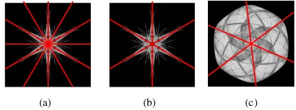
![Fig. 2.A sample of the patterns used in our experiments taken from the database used in [3].](https://thumb-us.123doks.com/thumbv2/123dok_us/8720810.384592/8.612.77.550.56.147/fig-sample-patterns-used-experiments-taken-database-used.webp)