TURBO
EQUALIZATION
OF CONVOLUTIONAL
CODED
AND
CONCATENATED
SPACE TIME
TRELLIS
CODED
SYSTEMS
USING
RADIAL
BASIS
FUNCTION
AIDED
EQUALIZERS
M. S. Yee, B. L. Yeap and L. Hanzo
Dept. of Electr. and Comp. SC., Univ. of Southampton, SO17 lBJ, UK.
Tel: +44-(0)23-8059 3125, Fax: +44-(0)23-8059 3045
Email: lh@ecs. soton. ac .uk
http://www-mobile.ecs.soton.ac.uk
Abstract - In this contribution a reduced-
complexity radial basis function (RBF) aided
neural-network based turbo equalization (TEQ)
scheme is proposed for employment in a serially
concatenated convolutional coded and system-
atic space time trellis coded (CC-SSTTC) ar-
rangement. A two-path Rayleigh fading chan-
nel having a normalised Doppler frequency of
3.3615 x lob5 was used. The BER performance
of the RBF-CC-SSTTC(4,4) scheme employing
a transmission burst consisting of 100 symbols
using a space-time-trellis (STT) interleaver of at
least 400 symbols and eight turbo equalization
iterations was found to be similar to that of the
CC-SSTTC system using a trellis-based TEQ,
which attains the optimum performance. How-
ever, the Jacobian RBF based TEQ provided a
complexity reduction factor of 14.
1. INTRODUCTION
The third-generation proposals aim for guaranteeing
low-cost, high-capacity mobile communications offer-
ing data rates of up to 2Mbps [l]. However, there
are a number of problems associated with high data rate transmissions, especially when aiming for creat- ing spectrally efficient systems. Systems transmitting at high bit rates, such as 2 Mbps, experience a high
grade of channel-induced dispersion and suffer from
Inter Symbol Interference (ISI). Therefore, typically
channel equalizers are employed for mitigating the ef-
fects of ISI. In addition to channel equalization, channel coding can also be invoked for further improving the performance of the system. Powerful error correction schemes, such as turbo codes [2], have been shown to yield a performance close to Shannonian performance limits. The discovery of turbo codes and turbo decod-
ing led to the development of turbo equalization [3].
Turbo equalization is a technique that performs chan-
nel equalization and channel decoding jointly and it-
eratively. This scheme has been shown to successfully
mitigate the effects of channel-induced ISI, resulting
in a Bit Error Rate (BER) performance close to that recorded for transmission over non-dispersive Gaussian channels.
The family of transmission diversity techniques re- ferred to as Space Time Trellis (STT) coding [4] pro- vides a substantial diversity gain for mobile stations by
upgrading the base stations, hence potentiallly increas-
ing the achievable user capacity of the system. STT coding [4] jointly designs the channel coding, modula- tion, transmit diversity and the optional receiver di-
versity schemes invoked. Following the research by
Tarokh et al. [4], Bauch et al. [5] proposed a joint equalization and STT decoding scheme, which yielded an improved performance with the advent of exploit- ing the soft-decision based feedback from the STT de- coder’s output to the channel equalizer’s input. In [6] the performance of the STT encoded system was fur- ther improved by employing additional channel encod-
ing in conjunction with turbo equalization. We refer to
this turbo equalizer as the TEQ-STTC scheme. How-
ever, due to the associated computational complexity,
the employment of this scheme was limited to low-order modulation modes, such as for example 4-level Quadra-
ture Amplitude Modulation (4QAM).
Motivated by these trends, in this contribution we
aim for reducing the complexity associated with the
channel-coded and concatenated STT encoded system
by using a reduced-complexity Jacobian Radial Ba-
sis Function (RBF) equalizer [7], which we will refer
to as the RBF-TEQ-STTC scheme. We will investi-
gate the BER performance achieved by the RBF-TEQ- STTC scheme and evaluate the achievable computa- tional complexity reduction compared to the conven-
tional trellis-based TEQ-STTC (CT-TEQ-STTC) ar-
Figure 1: Schematic of m-tap equalizer
2. RBF AIDED CHANNEL EQUALIZER
FOR SPACE-TIME-CODING
In this section we will show that the channel equaliza- tion problem encountered in a space-time coded system can be considered as a geometric classification problem [a], namely that of classifying an M-ary received pha- sor into one of M classes. Figure 1 shows an m-tap equalizer schematic, where the channel output observed by the equalizer can be written in vectorial form as
y/c! = [ Yk Yk-1 . . * Yk-m+1 ] . (1)
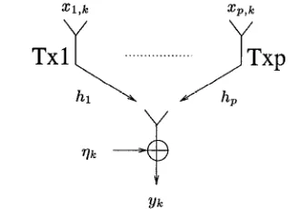
The baseband representation of the ptransmitter space-
time coded system is shown in Figure 2, which trans- mits a sequence of p symbols x1 = [ zr,]~ . . . %k 1 during each signalling instant Ic. The channel output at instant k is given by:
Yk =&ix% +Qk, (2)
i=l
where the i-th channel impulse response (CIR) hi =
[ ho,i h,i . . . hr, 1, having a memory of L sym-
bols, is convolved with a sequence of L + 1 transmitted
symbols, namely with x&k = [ z&k x+-r . . .
xi,k-~] and Q,+ is the additive Gaussian noise term hav-
ing a variance of (TV. For a ptransmitter system using
an m-tap equalizer and communicating over a chan-
nel having a CIR memory of L (assumming that all of the p CIRs have the same memory), there are n, =
M(“+L)‘p number of possible received phasor combina-
tions due to the transmitted sequence, hence producing n, number of different possible channel output vectors in the absence of channel noise:
yk = [ gk 812-l . . . @k--m+1 ] , (3)
where m is the length of the equalizer in Figure 1. Upon adding the noise we have: yk = Yk + vk. Expounding further, we denote each of the nS number of different possible combinations of the channel’s input sequence
j2k = [ x; . . . x;pm+l ] of length (L + m) x p sym-
bols as si,i = 1,. . . ,n,, where the channel’s input
state si determines the desired channel output state
ri,i = l,..., n,. This is formulated as:
Yk = ri, if %k = si, i = l,... ,nS. (4)
Yk
Figure 2: Baseband representation of ptransmitter
space-time coded system using one receiver.
For an M-level modulation scheme, the noisy channel
output states yk can be partitioned into MP classes
according to the sequence of p number of r-delayed
transmitted symbols, xiV7. The equalizer has to pro-
vide the associated non-linear decision boundaries for the classification strategy. The optimum equalizer is the so-called Bayesian equalizer [a], which has an exces- sive complexity. Hence here we advocate the reduced- complexity, but suboptimum Jacobian RBF equalizer, introduced in [7], which has N hidden nodes. The out- put of this Jacobian RBF equalizer can be represented
mathematically as [7]:
f&?dYk) = In 5 wi exd-bk - ciii2/x) (
(5)
i=l
= In
(
eeXp(h(wi) - llyk - Cil12/x)
i=l )
= J(dN,k,J(dN-l,k,... J(d2,k,&,k) . ..)).
where the terms wi, ci and X are the weights, centers
and width of the RBF nodes, respectively. Further-
more, we have di,k = exp(ln(wi) - ]]yk - c~]]~/X) and
J(&, 62) is the Jacobian logarithmic relationship de-
fined in [9] as J(&, Sz) = max(&,S2) + f,(ll& - 6211).
The correction function fc(x) = In(1 +exp(-x)) is tab-
ulated in a look-up table, in order to reduce the com-
putational complexity [9].
The full-complexity RBF equalizer provides the so-
called optimal Bayesian equalization solution [8] and
generates the conditional probability density functions
of MP number of possible transmitted symbols xiW7
emitted by the transmitters at instant Ic - r in the
form of:
p(Yk Ix;mT = Ij) = &I&~~cT;)-~/~ . i=l
exp
-&bk - %‘112} > 11 [image:2.600.86.246.74.148.2] [image:2.600.337.496.75.190.2]where the RBF parameters defined in the context of are then used for evaluating the a posteriori probabil-
Equation 6 are assigned the values of wi = pi,,j (27rai)-m/2, ity of the transmitted signal [a]. The schematic of the
ci = ri,j, N = nj, and X = 2aG. The term ni is the number of possible channel states ri,j correspond-
ing to the jth transmitted symbol sequence Ij of the
p-antenna SSTTC scheme that consist of p symbols, where we have j = 1,. . . , MP. The term pi,j is the
a priori probability of occurance of the channel state
ri,j. The a posteriori probability of the transmitted
symbols xi-, in Equation 6 provides the a posteriori
Log-Likelihood Ratio (LLR) values of the convolution-
ally coded symbols, which can then be fed to the STT decoder, as shown in Figure 4. The a priori probability of occurance of the ith channel state ri,j correspond-
ing to the transmitted symbol sequence Ij, pi,j, can
be evaluated from the LLRs generated by the STT de- coder as described in Section 3.
3. SYSTEM OVERVIEW
Source
El-
Systematic bits convolutionalencoder
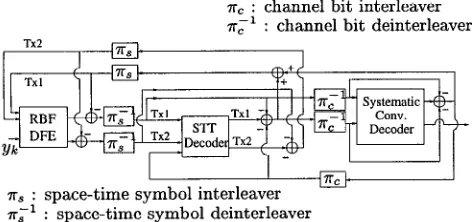
Figure 3: Transmitter of the serially concatenated sys- tematic convolutional coded and systematic STT coded system.
Rc : channel bit interleaver
-1
rc : channel bit deinterleaver
TX2
I I
I I xc
TITS : space-time symbol interleaver
-1
=s : space-time symbol deinterleaver
Figure 4: Receiver of the serially concatenated system-
atic convolutional coded and systematic STTC system
using RBF DFE assisted turbo equalization.
In an effort to create a low-complexity, high-per-
formance system, we employ the Jacobian RBF equal- izer [7] in the context of a turbo equalizer in conjunc- tion with a convolutional coded systematic STTC (CC-
SSTTC) system employing two transmitters. Specifi-
cally, we use the decision feedback assisted Jacobian RBF equalizer (Jacobian RBF DFE) [7] for the sake of
attaining a reduced computational complexity, where
the detected symbol is fed back to the equalizer for selecting a reduced-size subset of RBF centers, which
CC-SSTTC transmitter consists of a serially concate-
nated systematic convolutional encoder and a system-
atic STT encoder, as shown in Figure 3. The trans-
mitted source bits are convolutionally encoded and di-
rected to a random channel bit interleaver 71,. The con- volutional encoder denoted as CC(2,1,3) is a i-rate Re-
cursive Systematic Convolutional (RSC) coding scheme
having a constraint length of K = 3 and octal gener- ator polynomials of Go = 7 and Gr = 5. The RSC codeword consists of a systematic bit and a parity bit.
Subsequently, the encoded bits are passed to a sys- tematic STT encoder using two transmit antennas, as illustrated in Figure 3. We denote the systematic STT
encoder used as the SSTTC(n = 4,m = 4) scheme,
since it is an n = 4-state, m = 4-P% based STT code [4]. Upon receiving an input symbol, the SSTTC pro-
duces a symbol in each transmitter arm of Figure 3.
Note that we have employed the simple SSTTC(4,4) code instead of more complex systematic STT codes using a higher number of encoder states, since our aim was to invoke the turbo equalization principle and ‘in-
vest’ the affordable implementational complexity in a
number of consecutive iterations, rather than in a high-
complexity non-iterative decoder. The STT encoded
symbols are interleaved by a random STT symbol in- terleaver represented as r, in Figure 3.
The schematic of the receiver is shown in Figure 4. The channel equalizer of Figure 4 computes the aposte- riori LLR values for the systematic STT coded symbols of both transmitter TX1 and TX2. Subsequently, these LLR values are deinterleaved by the STT deinterleaver n;r of Figure 4 and passed to the SSTTC(4,4) decoder. In the first iteration, the channel equalizer only eval- uates the received signal yk, since there is no a priori
feedback information from the output of the RSC de-
coder. However, in subsequent iterations the channel
equalizer will receive additional a priori information
concerning the STT codeword from the other decoding stages. In order to avoid passing the a priori informa-
tion contributed by the other concatenated decoding
states back to these stages in Figure 4, we subtract the a priori LLRs fed back to the input of the equal- izer from the corresponding a posteriori LLRs output by the equalizer, in order to derive the combined chan-
nel and extrinsic information. Similar LLR subtraction
stages can be seen at the output of the STT decoder
and that of the convolutional decoder, again providing
the extrinsic information for the next component of the receiver, as detailed in [6].
[image:3.601.51.287.308.361.2] [image:3.601.51.288.426.537.2]tics obeyed a normalised Doppler frequency of 3.3615 x 10V5. The fading magnitude and phase was kept con- stant for the duration of a transmission burst, a con- dition which we refer to as employing burst-invariant fading. Furthermore, in order to investigate the best- case performance of these systems, we have assumed that the CIR was perfectly estimated at the receiver. Our future research will characterise the ability of the proposed turbo scheme to compensate for the effects of CIR estimation errors. At the receiver, the system-
atic STT decoder and the RSC decoder employed the Log-MAP algorithm [9]. The Jacobian RBF DFE has a feedforward order of m = 2, feedback order of n = 1 and decision delay of r = 1.
4. RESULTS AND DISCUSSION
10”
10-l
a 1o-2 m 1O-3
1o-4 t
1o-5
0 2 4 6 8 10 12 14 16
Eb&[dBl
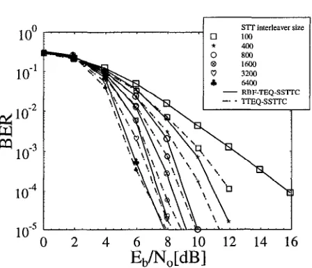
Figure 5: BER performance of the RBF DFE (m = 2,
n = 1, T = 1) assisted turbo-equalized serially con-
catenated convolutional coded and STTC system us-
ing various STTC interleaver sizes, namely 100, 400, 800, 1600, 3200 and 6400 symbols, after eight turbo
equalization iterations. The performance of the CT-
TEQ-SSTTC system is also shown as a benchmarker.
Figure 5 shows the performance of the proposed
RBF-TEQ-STTC and that of the CT-TEQ-STTC sche-
me [6], using various STTC interleaving sizes, namely 100, 400, 800, 1600, 3200 and 6400 symbols after eight
turbo equalization iterations. It was observed in Fig-
ure 5 that by increasing the STTC interleaving size
from 100 to 6400, the performance degradation of the
RBF-TEQ-STTC scheme compared to the CT-TEQ-
STTC arrangement expressed in terms of the excess
SNR required for attaining a BER of 10m4 decreases
from 3.8dB recorded for an STTC interleaver size of 100 symbols to OdB, as observed for the STTC inter- leaver size of 6400 symbols. This is because the error
propagation of the RBF DFE component decreases, as the BER performance improves, when using a longer
STTC interleaver. The performance difference of the
two schemes is less than 1dB at a STTC interleaver length of 400 symbols, although the RBF-TEQ-STTC
scheme has a lower computational complexity, when
the feedforward order m and feedback order n are set
to m = L + 1, n = L. The interleaving gain attained by
the RBF-TEQ-STTC scheme was approximately 9dB
at a BER of 10e4. Although higher interleaving gains can be achieved using longer STTC interleavers, the interleaver gain gradually saturates, when the STTC interleaver size is in excess of 1600 symbols.
;I
Table 1: Computational complexity of generating the
a posteriori LLRs for the trellis-based equalizer and
for the Jacobian RBF equalizer [lo]. The RBF equal- izer’s feedforward and feedback order are denoted by m and n, respectively, and the number of RBF nodes
is nf = M(“+L-“)‘p/M,i = 1,. . . , MP, where L is
the CIR memory and p is the number of STTC trans-
mitters. The notation n,,f = McL+l).P indicates the
number of trellis transitions encountered in the trellis- based equalizer and also the number of possible differ- ent noise-free channel outputs jjk of the Jacobian RBF equalizer.
Following the approach of our computational com-
plexity study in [lo], Table 1 summarises the computa- tional complexity of generating the a posteriori LLRs for each received signal at instant Ic in the context
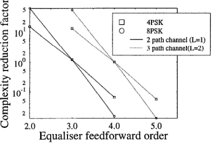
of a p-transmitter space-time coded system. Figure 6
demonstrates the complexity reduction achieved by the
Jacobian RBF DFE for various feedforward orders m,
over the trellis-based equalizer. The feedback order n and decision delay 7 of the RBF DFE was set to n = L and T = m for the sake of attaining the optimum per- formance, as stated in [8]. The performance of the RBF DFE improves, when increasing the feedforward order [8]. However, Figure 6 shows that the Jacobian RBF DFE only provides a significant complexity reduction compared to the trellis based equalizer, when the feed- forward order is less than L + 2 and imposes a higher
computational complexity for m > L + 2. Therefore, as
a rule of thumb, the feedforward order of the Jacobian RBF DFE must not exceed L + 1 in order to achieve
a computational complexity improvement relative to
the trellis-based equalizer. The complexity imposed by
the RBF-TEQ-STTC scheme using an equalizer feed-
[image:4.599.312.551.238.288.2] [image:4.599.57.281.274.466.2]I
4PSK XPSK
- 2 path channel (L=l) ‘..‘.‘. 3 path channel(L=Z)
u 2.0 4.0 5.0
l3cpa&k- feedforward order
Figure 6: Complexity reduction factor achieved by the RBF DFE equalizer over the trellis based equalizer ac- cording to Table 1. The feedback order n was set to L and the number of transmitters was two.
to be a factor of 14 lower, than that of the CT-TEQ-
STTC scheme in the context of a two transmitter, one
receiver system, based on the general complexity ex- pressions of Table 1. For example, if we used a higher order modulation mode, such as 8PSK used in [4] along with the same number of transmitters, as well as equal- izer and channel parameters, the achievable computa- tional complexity reduction is a factor of 55, as shown in Figure 6.
5. CONCLUSIONS
A turbo equalization scheme using the Jacobian RBF equalizer principle of [7] was invoked in a serially con-
catenated systematic convolutional coded and system-
atic STT coded system. It was observed in Figure 5 that the BER performance degradation compared to the CT-TEQ-STTC system [6] was less than 1dB for a STTC interleaver length of 400 symbols, while achiev-
ing a computational complexity reduction factor 14.
Hence, the Jacobian RBF equalizer based TEQ con- stitutes a better design choice in STTC systems, espe- cially in the context of complex STTC schemes, having a high number of encoder states. Near-optimum perfor- mance was achieved, provided that a sufficiently high STTC interleaver length was affordable.
6. REFERENCES
[l] T. Ojanpera and R. Prasad, Wideband CDMA
for Third Generation Mobile Communications.
Artech House, 1998.
[2] C. Berrou, A. Glavieux, and P. Thitimajshima,
“Near Shannon Limit Error-Correcting Coding
and Decoding: Turbo Codes,” in Proceedings of
the International Conference on Communications,
(Geneva, Switzerland), pp. 1064-1070, 23-26 May 1993.
[3] C. Douillard, A. Picart, M. JCzequel, P. Di-
dier, C. Berrou, and A. Glavieux, “Iterative
correction of intersymbol interference: Turbo-
equalization,” European Transactions on Commu-
nications, vol. 6, pp. 507-511, September-October 1995.
[4] V. Tarokh, N. Seshadri, and A. R. Calderbank, “Space-Time Codes for High Data Rate Wireless
Communication: Performance Criterion and Code
Construction,” IEEE Transactions on Informa-
tion Theory, vol. 44, pp. 744-765, March 1998.
[5] G. Bauch, A. F. Naguib, and N. Seshadri, “MAP
Equalization of Space-time Coded Signals over
Frequency Selective Channels,” in Proceedings
of the Wireless Communications and Networking
Confeerence, (New Orleans, USA), pp. 261-265, September 1999.
[6] B. L. Yeap, T. H. Liew, and L. Hanzo, “Turbo
equalization of serially concatenated systematic
convolutional codes and systematic space time
trellis codes,” in Proceedings of the IEEE Vehicu- lar Technology Conference, (Rhodes, Greece), 6 - 9 May 2001. CD-ROM.
[7] M. S. Yee, T. H. Liew, and L. Hanzo, “Block
turbo coded burst-by-burst adaptive radial ba-
sis function decision feedback equaliser assisted
modems,” in Proceedings of IEEE Vehicular Tech-
nology Conference, vol. 3, (Amsterdam, Nether-
lands), pp. 1600-1604, September 1999.
[8] S. Chen, S. McLaughlin, and B. Mulgrew,
“Complex-valued radial basis function network,
Part II: Application to digital communications
channel equalisation,” EURASIP Signal Process-
ing, vol. 36, pp. 175-188, March 1994.
[9] P. Robertson, E. Villebrun, and P. Hoeher, “A
Comparison of Optimal and Sub-Optimal MAP
Decoding Algorithms Operating in the Log Do-
main,” in Proceedings of the International Con-
ference on Communications, (Seattle, United
States), pp. 1009-1013, 18-22 June 1995.
[lo] M. S. Yee, B. L. Yeap, and L. Hanzo, “Radial Ba-
sis Function Assisted Turbo Equalisation,” in Pro-
[image:5.599.65.279.76.219.2]