Abstract— Trucks are one of the most common kinds of transport and they are operated in various road conditions. As a rule, all-wheel drive trucks are equipped with special systems and mechanisms to improve their off-road capability and overall efficiency. The usage of blocked mechanisms for power distribution is one of the most popular and effective ways to improve the off-road vehicle performance. However, the lock of differential may adversely affect the stability and control of vehicle because of the unobvious redistribution of reactions acting on wheels, which consequently leads to poor performance and safety properties. Problems of rational distribution of power in transmissions of all-wheel drive vehicles, as well as research in the field of improving directional stability and active safety systems are among the priorities in modern automotive industry. To study dynamics of a vehicle with wheel formula 6x6 a mathematical model of the vehicle was developed in an environment of LMS Amesim software package. The model includes the realization of the features of all major mechanical units of a vehicle: engine, transmission, suspension, drive wheels. Besides, the model takes into account the so called "external" dynamics of the vehicle and includes interaction of the wheels and pavement and implementation of possible changes in environmental conditions. With help of the mathematical model we have managed to estimate the trajectory and directional stability of all-wheel drive trucks with lockable differentials for different operating conditions. The results allowed us to develop the most effective, in terms of stability and control, algorithm for control of the power distribution system.
Index Terms— Stability, control of movement, all-wheel drive vehicles
Manuscript received July 23, 2017. The work was supported by Act 211 Government of the Russian Federation, contract № 02.A03.21.
The work was conducted with the financial support of the Ministry of Education and Science of the Russian Federation in the framework of the complex project to create a high-tech production "Creating high-tech production of a new generation of energy efficient transmissions for trucks and buses" under contract No. 02.G25.31.0142 dated "01" December 2015 between the Ministry of Education and Science of the Russian Federation and Public Joint-Stock Company "KAMAZ" in cooperation with the head executor of the research, development and technological work of civil purpose - Federal State Autonomous Educational Institution of Higher Education "South Ural State University (National Research University)".
A. V. Keller is with the South Ural State University, 76 Prospekt Lenina, Chelyabinsk, 454080, Russian Federation (e-mail: [email protected]).
S. V. Aliukov is with the South Ural State University, 76 Prospekt Lenina, Chelyabinsk, 454080, Russian Federation (corresponding author, home phone: +7-351-267-97-81; sell phone: 8-922-6350-198; e-mail: [email protected]).
V. V. Anchukov is with the South Ural State University, 76 Prospekt Lenina, Chelyabinsk, 454080, Russian Federation (e-mail: [email protected]).
I. INTRODUCTION
he method of implementation of rigid kinematic constraints in transmission is quite effective in terms of increasing of possibility of a wheeled vehicle [12,13]. However, the movement with locked differentials has several disadvantages, the most significant one includes deterioration of controllability and course stability of the vehicle. Accordingly, to maintain and enhance these important performance properties, it is necessary to search optimal laws of power distribution. As a rule, the system of active power distribution includes the following main elements: means of collecting and evaluating information on the current operating mode, the control unit, actuators, power-sharing arrangements and other necessary mechanical elements.
Thus, the problem of control of power flow in the transmission of the wheeled vehicle is quite difficult and multidisciplinary. Significant investigation in this area belongs to V.V. Vantsevich, Josko Deur, Vladimir Ivanović, Matthew Hancock, Francis Assadian. For example, in [9] V.V. Vantsevich, Dennis Murphy and Gianantonio Bortolin made estimation of energy efficiency and fuel economy of a vehicle type of 6x6 by method of combination in transmissions of different differential mechanisms of power distribution. The authors suggested three drivetrain configurations and by drawing up mathematical models they carried out a comparative analysis with help of criteria of energy efficiency in the case of slippage of wheels.
The use of the locking differential mechanisms in wheeled vehicles to improve mobility and other dynamic characteristics is very important, it is devoted a large part of the following work.
Paper [2] presents a mathematical model of four types of active locking differentials: ALSD; clutch TVD superposition; stationary clutch TVD; TVD 4WD. The authors verified the developed mathematical model of differential ALSD experimentally. The results indicate a high degree of accuracy of the model. Description of experiment and summary are presented in [7].
In the paper [6] the authors developed a mathematical model of the semi active differential with electromagnetic actuator. The simulation results were presented and conclusions about the usefulness of this type of mechanism for power distribution were formed as well.
The next step of the development of the locking differentials was usage of intelligent control systems, working independently, without any direct participation of
Mathematical Model of the Truck for
Investigation of Stability and Control of
Movement
A. Keller, S. Aliukov, and V. Anchukov
a driver. This issue is dedicated to the paper [10]. The authors suggested a model of autonomous controlled mechanism of power distribution. Also it was developed an algorithm to control of this mechanism. The algorithm allows controlling power flow transmitted to drive wheels, and, as a result, improving mobility of a wheeled vehicle. Besides, it was represented the results of simulation of motion of four-wheel vehicle with usage in transmission the above-mentioned mechanisms as two cross-axle and one inter-axle differentials. Estimation of their influence on the overall dynamic performance of the vehicle was done.
Similarly, in the paper [1] it was described the mathematical model of the lockable differential with a system of control. Effectiveness of this solution was evaluated.
Continuous and intensive growth of the number of vehicles in different countries and improvement of traction-speed qualities of the vehicles led to a sharp increase in the accident rate in road transport. One of the main directions of the improvement of the vehicles and the most important direction of the improvement of trucks is increasing safety of the traffic.
Active safety systems aimed at preventing emergency situations and help drivers in case of extreme modes of movement.
II. DESCRIPTION OF THE MATHEMATICAL MODEL
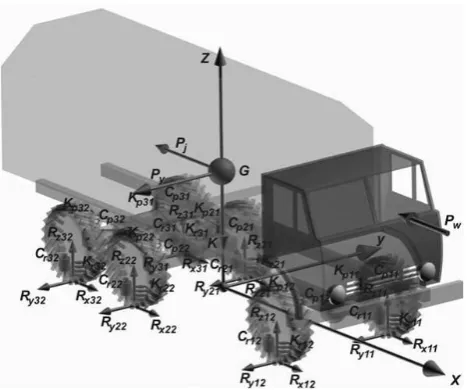
[image:2.595.310.546.216.410.2]Mathematical model of process of movement of a vehicle should include all of the major subsystems of the vehicle together with the actual characteristics of the particular object of study [14-16]. Only in this case it is possible to obtain reliable results and their further use in the process of design of the vehicle. Estimated vehicle scheme 6x6 is shown in Figure 1.
Fig.1. Estimated vehicle scheme 6x6
Assessment of dynamic load acting on transmissions is done by means of simulation in LMS Imagine Lab AMESim package. The developed mathematical model shows the process of movement of a vehicle on required modes, taking into account the specific features of dynamics of components and assemblies.
Figure 2 illustrates a general view of the model implemented in the LMS Imagine Lab AMESim package. The model includes all subsystems of the vehicle: engine, transmission, suspension system and takes into account all physical characteristics of the vehicle and the environment: mass-inertial characteristics, implementation of interaction with the wheel bearing surface, especially road conditions and force of air resistance.
The body of the vehicle is a solid one to which forces and displacement determined by power unit and external environment are transmitted. The equations of motion of the body relative to a fixed coordinate system in the form of Lagrange type II are the following:
1 2 3
2 2 2
12 2 2 3 3 1 1 1
1 1 1
3 3 2 2 2 1 3 2 2 1 1 3 ( ) /
0, 5( )
0, 5
/
/
s COG x y z
x y
y x
i i i right left
y y y x x
i i i
right left xj xj j j z i xj j i i yj i
T G h V V J
V V T
V V T
R a R b R b R R B
R R B
T
J
T R G
T R G
3 2 1 1 j
here
is velocity of rotation of body relatively vertical axis;S
G
is sprung weight of vehicle;
G
is total mass of vehicle; COGh
is height of center of gravity;
is angle of deflection of body deflection in horizontal plane;X
V
is speed of vehicle in the longitudinal direction;Y
V
is speed of vehicle in the transverse direction;Z
J
is moment of inertia of body relatively vertical axis;X
R
is longitudinal reaction of wheel;Y
R
is transverse reaction of wheel;a
is distance from the front axle to the center of gravity;2
b
is distance from center of gravity to the central axis;3
b
is distance from center of gravity to the rear axle;1
B
is front track;3
B
is rear track.Engine-transmission unit includes a motor, working according to partial speed characteristics, transmission, yielding cardan shafts with consideration of gaps in joints, five differential mechanisms (two axle and three cross-axle ones) and main transmissions on each axis.
[image:2.595.49.283.477.672.2]Rocard/Brossard, which is based on the following assumptions:
• deformation of the center line of tread is a result of lateral and longitudinal slip;
• the model does not account for the tire grip in the longitudinal and transverse directions;
• vertical load is evenly distributed on the contact patch; • in the case of slipping of the tread with respect to the road surface, deformation of the tread is uniform;
• magnitude of normal force and relative speed of the sliding do not affect friction factor.
Fig.2. General view of the mathematical model in the environment of the LMS Imagine Lab AMESim package
Maintaining a predetermined driving mode is provided by the system "virtual driver", which is a set of measuring tools of condition of the car. The "virtual driver" system solves the following tasks: control of gas and clutch pedals, gear changes, braking and holding the desired trajectory.
III. MANOEURING "PERMUTATION" AND "CLOSED PERMUTATION"
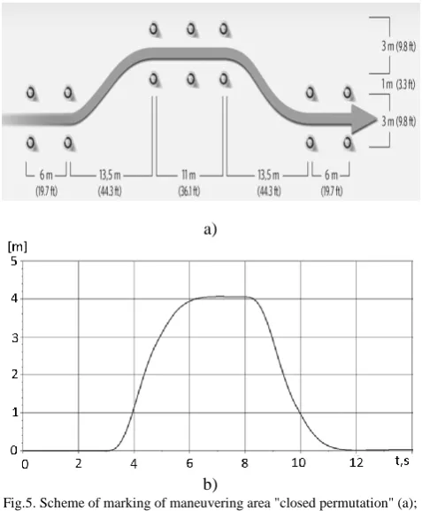
To perform settlement cases corresponding curvilinear motion of the mathematical model, there were selected two typical maneuvers, commonly used to evaluate the stability and control of vehicles, namely: "permutation 20 m." and "closed permutation". Maneuver "permutation 20 m." is described in ISO 31507-2012, maneuver "closed permutation" or «double lane-change» is described in ISO 3888-1: 1999 (E). Initial data for calculation of the two cases are shown in Table I, the results are illustrated in Figures 3-6.
As seen from these graphs, the trajectory of the vehicle is allowed to move in the given conditions. In the case of the maneuver "permutation 20 m." moving the vehicle center of gravity in the lateral direction was 3.6 m For maneuver "closed permutation" it was 4 m. Comparing these results with the options of the marking for performing each maneuver, it can be concluded that each maneuver is executed in the normal mode.
TABLEI
INITIAL DATA FOR THE SETTLEMENT CASE "PERMUTATION 20 M."
AND "CLOSED PERMUTATION"
Mode of movement
The initial state of truck Driving at a constant speed of 40 km/h The coefficient of adhesion support
surface
0,8
Transmission Mode of work of transmission
Status of differentials All are unlocked № of gear 7 (i = 2,2) Gear shift Absent The power distribution between the
front axle and the truck
1:2 Throttle position Full fuel supply
a)
b)
Fig.3. Scheme of marking of maneuvering area (a); trajectory of movement of the truck when maneuvering "permutation 20 m." (b)
a)
[image:4.595.46.285.49.338.2]b)
Fig.5. Scheme of marking of maneuvering area "closed permutation" (a); trajectory of movement of the truck when maneuvering "closed
[image:4.595.326.539.263.386.2]permutation" (b)
Fig.6. Changing the yaw speed while driving
IV. ASSESSING IMPACT OF INTRODUCTION OF RIGID KINEMATIC CONNECTION ON STABILITY OF THE VEHICLE
Locking of differentials while driving leads to non-obvious redistribution of reactions on vehicle wheels, which in turn can entail some negative consequences, such as loss of directional stability of motion. To maintain the directional and trajectory stability of the truck we make a function algorithm for system of stabilization of the directional stability based on differential braking. For calculations we use the so called "single-track" model of the truck, which is shown in Figure 7.
Let us describe all the physical quantities shown in Figure 7.
X,Y are coordinates of motion of center of mass of the vehicle, m;
ψ is yaw angle of the vehicle relatively to the center of mass, rad;
β is vehicle slip angle relatively to the center of mass, rad;
a,b,c are distances between axes of the wheels and the center of mass, m;
l1 is distance between the first and the second wheel axis, m;
l2 is distance between the first and the third wheel axis, m;
Fy1, Fy2, Fy3 are transverse forces arising during turning, H;
δ is angle of turning of the front wheels, rad; α1, α2, α3 are slip angles of wheels, rad;
Vx is longitudinal velocity of the vehicle relatively to the center of mass, m/s;
Vy is transverse velocity of the vehicle relatively to the center of mass, m/s;
M is torque of the center of mass relatively to vertical axis, H∙m.
ψ ,M 0 x
y Vy
Vx
V Fy2
l1
l2
β δ
α1
α2
Fy1
a
b c
α3 Fy3
Fig.7. "Bicycle" model of three-axle vehicle
The trajectory is described by the equations:
cos
x
X
V
,
sin
x
Y
V
.As expected, the speed remains constant (Vx = const), then the trajectory depends on the angles ψ and β. According to Newton's second law for rotational and translational motion of the center of mass we have:
1 2 3,
y y y
Jψ M aF bF cF
1 2 3
,
x y y y bank
β
mV
ψ
F
F
F
F
t
here J is moment of inertia of the center of mass relatively vertical axis, H∙m2;
m is mass of the truck with respect to the center of mass, kg.
The differential braking of wheels is one of the main methods for many control systems of vehicles, including directional stability. The essence of this method will be discussed below, based on Figure 8.
The essence of this method lies in the fact that braking left (right) wheels on the rear axles of the truck, the forces on the right (left) wheels become larger opposite ones. Thus, it is created a torque (
M
f ) acting on the truckaround its center of gravity. Torque applied to the center of mass of the truck, is produced by differential braking of the rear wheels. Link between this torque and the braking force is defined as:
2, 2,
3, 3,
(
)(
)
.
4
R L R Lf
[image:4.595.49.283.380.506.2]Fig.8. Geometrical parameters of rear wheels of three-axle truck
Figure 9 illustrates a functional scheme of the system of stabilization of directional stability.
Fig. 9. Structural control scheme using the directional stability of the system with feedback on the angular velocity
Here
ε ψ
р
ψ
is error between actual and desired the actual and the desired angular speed;i p
k u k ε ε
s
is control action regulating the supply of pressure on the brake cylinder;
are coefficients of proportional and integral controllers.
To assess workability, we ask the system of stabilization of directional stability to perform the maneuver "permutation 20 m." with different coefficients of adhesion under the left and right wheels. Description of the design case is shown in Table II.
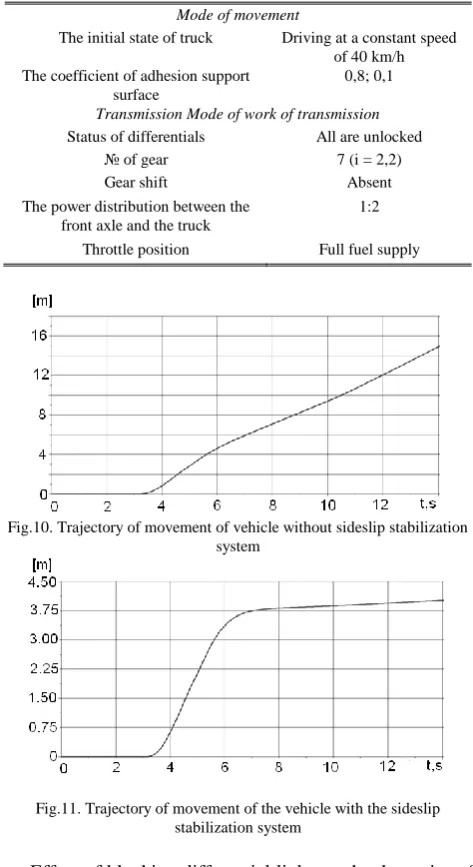
Figures 10-11 illustrate graphs of changing the transverse coordinate position of the center of gravity in space of driving for two cases: the movement without stabilization system of directional stability and movement when this system is available.
These results clearly demonstrate the effectiveness of the system. Movement of the vehicle under the given conditions without sideslip stabilization system leads to a serious deviation from desired trajectory and therefore, to an unsatisfactory result maneuver.
As shown in Figure 11, the use of sideslip stabilization system functioning on the principle of differential inhibition, promotes satisfactory maneuvers "permutation 20 m." on a given mode of movement.
TABLEII
INITIAL CONDITIONS OF THE SETTLEMENT CASE "PERMUTATION 20 M." WITH DIFFERENT COEFFICIENTS OF ADHESION UNDER THE VEHICLE SIDES
Mode of movement
The initial state of truck Driving at a constant speed of 40 km/h The coefficient of adhesion support
surface
0,8; 0,1
Transmission Mode of work of transmission
Status of differentials All are unlocked № of gear 7 (i = 2,2) Gear shift Absent The power distribution between the
front axle and the truck
[image:5.595.311.548.78.512.2]1:2 Throttle position Full fuel supply
Fig.10. Trajectory of movement of vehicle without sideslip stabilization system
Fig.11. Trajectory of movement of the vehicle with the sideslip stabilization system
[image:5.595.56.275.323.406.2]Effect of blocking differential links on the dynamics of the vehicle we estimate with help of the following case: the vehicle is moving at a constant pace on support base with a constant coefficient of adhesion, then one side comes over on the site with lower value of the coefficient of adhesion. The results are illustrated in Figures 12-14.
[image:5.595.328.529.597.731.2]Graph of trajectory of the vehicle (Figure 12, 1) demonstrates the process of movement of the vehicle from desired trajectory, caused by the introduction of rigid kinematic connection. By the nature of changing graphs of rotation speed and torques of output shafts of the transfer case it is possible to observe the process of working the system of stability. Designed algorithm can be considered as effective because its usage led to withdrawal from the desired trajectory of less than 0.5 meters, which is valid for driving on public roads with a width of one lane of 2.75 m.
Fig.13. Changing speed of rotation of output shafts of transfer case (1, 2). Signal of switching differential lock - 3.
Fig.14. Changing speed of rotation of output shafts of transfer case (1, 2). Signal of switching differential lock - 3.
Based on our investigations we have developed the methodology of proper power distribution among wheels has been developed. The developed methodology is based on:
• the theory of operational properties of wheeled vehicles;
• the theory of rolling elastic wheels;
• optimal control theory;
• principles and methods of a systematic approach. It has been done study of different methods of power distribution among the drive wheels of an all-wheel-drive truck, namely:
• method of partial solution;
• method of introducing a rigid kinematic connection;
• method of periodical action;
• and method of limit of excessive action. We have proved the following.
On the mode of acceleration up to 30 km/h, a rigid kinematic connection among driving axles and wheels of unmanaged axels should be switched on. After reaching velocity of 30 km/h it should be provided disconnection of the rigid link and then a differential connection among drive wheels. Upon reaching of steady velocity and
slippage of the drive wheels less than 5%, front axle should be switched off. With increasing of the slippage of the drive wheels more than 5%, full differential drive should be switched on.
V. CONCLUSION
The developed system to control power distribution of torque allows us to improve significantly vehicle's passability. At the same time on some driving modes there is a loss of directional stability of the vehicle when rigid kinematic connection is introduced during the driving. To solve this problem, a system of stabilization of directional stability was developed, which operates on the principle of differential braking wheels of the vehicle. Thus, it can be concluded that providing the necessary operational parameters of the vehicle is achieved by co-operation of the power distribution and the control system for stabilization of directional stability.
REFERENCES
[1] Cheli, F., Pedrinelli, M., Fortina, A. and Martella, P., "Vehicle Dynamics Control System Actuating an Active Differential, ASME 42495, 2006, pp. 251-260.
[2] Assadian, F., Hancock, M. and Deur, J., "Modeling of Active Differential Dynamics," ASME 48784, 2008, pp. 427-436. [3] Tobler, W., Zhang, X., Chen, X., Zou, Z. et al., "Modeling and
Analysis of Vehicle Transmissions in Modelica," Dymola Environment, ASME 36215, 2002, pp. 843-850.
[4] Ebrahimi, M. and Whalley, R., "Power Transmission System Modeling," ASME 47381, 2005, pp. 2107-2111.
[5] González-Cruz, C., Jáuregui-Correa, J., López-Cajún, C. et al., "Dynamic Behavior and Synchronization of an Automobile as a Complex System," ASME 45837, vol.1, 2014.
[6] Annicchiaricom, C., Rinchi, M., Pellari, S. and Capitani, R., "Design of a Semi Active Differential to Improve the Vehicle Dynamics," ASME 45837, vol.1, 2014.
[7] Assadian, F., Hancock, M., Herold, Z., Deur, J. et al., "Modeling and Experimental Validation of Active Limited Slip Differential Clutch Dynamics," ASME 48784, 2008, pp. 295-304.
[8] Kharytonchyk, S., Zakrevskij, A. and V. Vantsevich, "Heavy-Duty Truck: Inverse Dynamics and Performance Control," ASME 43033, 2007, pp. 345-354.
[9] Vantsevich, V., Murphy, D. and Bortolin, G., "Driveline Configuration Effect on Longitudinal Vectoring of Power Flow Between Drive Wheels and Energy Efficiency in Transport Mode of a 6×6 Terrain Truck," ASME 45059, 2012, pp. 379-388. [10] Vantsevich, V. and Shyrokau, B., "Autonomously Operated
Power-Dividing Unit for Driveline Modeling and AWD Vehicle Dynamics Control," ASME 43352, 2008, pp. 891-898.
[11] Xie, Y., Mashadi, Mostaani, A., Mostaani, S., "Active Differentials," ICMET-China, 2011.
[12] Keller, A., Aliukov, S., Anchukov, V. and Ushnurcev, S., "Investigations of Power Distribution in Transmissions of Heavy Trucks," SAE Technical Paper 2016-01-1100, 2016, doi:10.4271/2016-01-1100.
[13] Keller, A., Murog, I. and Aliukov, S., "Comparative Analysis of Methods of Power Distribution in Mechanical Transmissions and Evaluation of their Effectiveness," SAE Technical Paper 2015-01-1097, 2015, doi:10.4271/2015-01-1097.
[14] Keller, A. and Aliukov, S., "Rational Criteria for Power Distribution in All-wheel-drive Trucks," SAE Technical Paper 2015-01-2786, 2015, doi:10.4271/2015-01-2786.
[15] Dubrovskiy, A., Aliukov, S., Keller, A., Dubrovskiy, S. et al., "Adaptive Suspension of Vehicles with Wide Range of Control," SAE Technical Paper 2016-01-8032, 2016, doi:10.4271/2016-01-8032.