Neurofuzzy Control Applied to Five Links Biped Robot
using Particle Swarm Optimization Algorithm
Ammar A. Aldair
Department of Electrical Engineering University of Basrah, Iraq
Hayder H. Abbood
Department of Electrical Engineeing University of Basrah, Iraq
ABSTRACT
The biped robot consists of five links, namely the torso and two links in each leg. Four rotating joints (two hips and two knees) are used to connect these links together to make the biped robot model resemble the human being model. The four rotating joints are driven by independent servo motors via control signals generated from designed control systems. The biped walking is difficult to control because it is a nonlinear system with various uncertainties. In this paper, the application of Neurofuzzy control to a nonlinear five links biped robotic model is studied and compared to designed PD controllers which are applied to the given model. First of all, the optimal parameters of four PD controllers are selected using Particle Swarm Optimization (PSO) algorithm to drive four servo motors of biped robot. Then, the parameters of four fuzzy controllers are tuned using neural networks depend on the input-output data which are collected from the designed PD controllers. To make the designed Neurofuzzy controllers more robust, the optimal inputs and outputs gains of the designed controller are selected using PSO algorithm. The proposed controllers are tested in different environments such as: moving on rough terrain with random profile and climbing the stairs. The results of numerical simulation clearly indicate the robustness and effectiveness of the proposed controller to drive the five links biped robot.
Keywords
Biped robot, Neurofuzzy control, PD control, Particle Swarm Optimization algorithm
1.
INTRODUCTION
Robots have become more widely used in different applications instead of human being such as: military application, space application, medical application, dangerous and harm sites and so on. The design of control system for biped robot is big challenging subject because the high nonlinearity and complexity of biped robot model. Biped robot is on type of legged robots that attempt to imitate the human motion. Many structures are used to model the legged robots. The authors in [1] and [2] used the simplest model to investigate some characteristics of human motion is the inverted pendulum. To study more characteristics of human locomotion and imitate the human walking, author in [3] employed a three links biped robot model (torso and two legs). To simulate the actual human walking, some authors are used five links biped robot (one torso, two hips and two knees) [4-9]. Other authors are used more than two legs to imitate insect’s locomotaion [10,11]
It is difficult to design a control system for five links biped robot due to it has high nonlinear behavior model. In recent years, several controllers have been developed in attempts to increase the stability of the biped robot when it moves on rough terrain with random profile and climbs the stairs. Also, some authors pay attention to design a complex control
system to force the locomotion of the biped robot resembles the locomotion of human being. Authors in [12] investigated the application of robust control to a 5-1ink biped robotic model through the sliding mode approach and compared the responses of the proposed controller to pure computed torque control. In [13], the authors improved approach to the dynamic modeling of a 5-link biped system and developed a sliding mode control algorithm for biped motion regulation during double support phase. They assumed that the boundaries of the system uncertainties are known. In [14], the authors designed a robust control system based on sliding-mode control (SMC) of 5-link biped robot using the wavelet neural network (WNN), in order to improve the efficiency of position tracking performance of biped locomotion. In this control system, the WNN is utilized to estimate uncertain and nonlinear system parameters, where the weights of WNN are trained by adaptive laws that are induced from the Lyapunov stability theorem. The authors applied sliding mode control approach for both the single support phase and the double support phase. Then, a new chattering elimination method using fuzzy system proposed based on regulating major controller parameters. In [8], the authors proposed a new adaptive neural network integral sliding-mode controller using a bat algorithm to control a five links biped robot. The phenomenon of chattering occurs when there is a discontinuity in feedback control. An adaptive neural network is applied to estimate the unknown disturbances to the system. Therefore, by using an adaptive neural network, the chattering phenomena will be eliminated. The neural network integral sliding-mode controller parameters are tuned using a bat algorithm.
robots is summarized [20]. Also, this work presents a new approach neuro-fuzzy system.
In this paper, a new approach is proposed to design a neurofuzzy controller to oblige five links biped robot walking resemble the human being walking for different environment (such as moving on rough terrain with random profile and climbing the stairs) and to increase the stability of the biped robot. The designing of the proposed controller has three main steps. In the first step, the optimal parameters of four PD controllers are selected using Particle Swarm Optimization (PSO) algorithm to drive four servo motors of biped robot. While in the second step, depending on the input-output data which are collected from the designed PD controllers, the parameters of four fuzzy controllers are tuned using neural networks. Finally, to make the designed Neurofuzzy controllers more robust, the optimal inputs and outputs gains of the designed controller are selected using PSO algorithm. The proposed controllers are tested in different environments such as: moving on rough terrain with random profile and climbing the stairs. The results of numerical simulation clearly indicate the robustness and effectiveness of the proposed controller to drive the five links biped robot.
2.
DYNAMIC MODEL OF FIVE LINKS
BIPED ROBOT
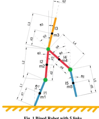
In this work, the studied biped robot consists of five links, one link for torso and two links in each leg is shown in Figure 1. These links are connected via four rotating joints (two hips and two knees) which are driven by four independent servo motors. The servo motors are excited via the generated control signals which are came from the proposed controller. The Lagrange dynamic equation to model and describing the motion of biped robot is used [12]. The kinematic model of biped robot can be written as:
where
Θ = [θ1 θ2 θ3 θ4 θ5] is angle of link with respect to the vertical.
is the inertia matrix; is the centrifugal
matrix;
is the vector of gravity;
is the vector of external torque applied at the joints;
[image:2.595.320.523.75.319.2]The parameters of and are given in Appendix1 [12].
Fig. 1 Biped Robot with 5 links
If is assumed as the vector of the driving torques of the four joint of biped robot generated from the servo motors, then the following equation can be written as:
where is transformation matrix which can be given as:
As shown in Figure 1, the relative angle deflections of the corresponding joints ( ) is given as:
Then the equation 1 can be written as:
where is the inertia matrix with respect to ; is the centrifugal matrix with respect to ;
is the vector of gravity with respect to ;
Then, the dynamic equations for five links biped robot can be defined as
3.
PARTICLE SWARM
OPTIMIZATION (PSO) ALGORITHM
In last a few decades, the world becomes more and more complex and competitive so the decision making must be taken in an optimal way. The particle swarm optimization algorithm is developed by scientists and engineers to find the best solution for problems featuring nonlinearity and no differentiability, multiple optima, and high dimensionality within shorter calculation time its convergence is usually faster than other optimization algorithms. Authors in [21] introduced particle swarm optimization algorithm in 1995. This algorithm is stochastic in nature like genetic algorithm. On the other hands, the differences between this algorithm and GA are that the PSO does not depend on the principle of ‘survival of the fittest’, is computationally less burdening since its memory and processing speed requirements are low, and does not use evolutionary operators such as crossover and mutation [22,23].
Each particle in this algorithm is treated as a valueless particle in g-dimensional search space, and keeps track of its coordinates in the problem space associated with the best solution (evaluating value) and this value is called pbestt. The
overall best value and its location obtained so far by any particle in the group that was tracked by the global version of the particle swarm optimizer gbest. The PSO concept consists of changing the velocity of each particle toward its pbestt and
gbest locations at each time step. The modified velocity and position of each particle can be calculated using the current velocity and distance from pbestt to gbest as shown in the
following formulas [21]:
where;
n is any number and
is number of particles in a group; is number of members in a particle; is pointer of iterations;
is velocity of particle at iteration
is inertia weight factor;
are acceleration constants (according to past experience the addition of equal to 4);
is random function with respect to ;
current position of particle at iteration
The inertia weight is selected according to equation below.
where itermax is the maximum number of iterations and iter is
the current number of iterations.
Suitable selection of W provides a balance between global and local explorations, thus requiring less iteration on average to find a sufficiently optimal solution.
4.
PARAMETERS TUNING OF PID
CONTROLLER USING PSO
ALGORITHM
The popularity of PID controller is due to the simplicity of their control law, robustness in a wide range of operating conditions and few tuning parameters are needed. Furthermore, the PID controller is easier to implement and understand than other traditional controllers for the majority of industrial processes and the familiarity of operators and designers with the PID algorithms Coban, R. and Ercin O. (2012).
The PID controller involves three parameters , its performance completely depends on the tuning of these parameters, and the task to tuning these parameters properly for the PID controller is quite difficult. So in spite of the popularity of PID controller but it is often poorly tuned in practice. The robustness and optimization are difficult to achieve with these types of controllers because many industrial plants are often confronted with many problems such as higher order plant, time delays and system nonlinearity [24].
Many efforts have been made to overcome this problem, where different techniques have been introduced to determine the best parameters of PID controller, such as Ziegler-Nichols method, Cohen-Coon method and so on [25].
On the other hand, this algorithm also have disadvantages or drawbacks, where the Cohen-Coon method is used only forfirst order models including large process delays, while the Ziegler and Nichols tuning method is mostly utilized to determine optimal PID gains for the plant with certain operating point. However, if the parameters of the plant are changed because the uncertainty or nonlinearity, those methods provide poor performance and the controller become not robust and not in optimum state [26].
In recent decade, design engineers have focused on evolutionary based approaches to improve the existing design theories to tune the parameters of PID controllers. The several optimization methods have been proposed to optimize the parameters of PID controller such as genetic algorithm (GA), Particle Swarm Optimization (PSO) method, ant colony optimization (ACO) method. Those methods provide new techniques for tuning the PID parameters of controllers [27]. In this paper, an optimization algorithm PSO is introduced to optimize the parameters of PID controller to design control system for five link biped robot model to oblige biped robot walking resemble the human being walking for different environment and to increase the stability of the biped robot. Stochastic Algorithm can be applied to the tuning of PID controller gains to ensure optimal control performance at nominal operating conditions. PSO is employed to tune PID gains/parameters ( ) in offline using biped robot model. PSO firstly produces initial swarm of particles in search space represented by matrix. Each particle represents a candidate solution for PID parameters where their values are set in the range of . For this
where is the difference between the desired value and the actual value of the system output.
5.
THE STRUCTURE OF
NEUROFUZZY SYSTEM
The main disadvantage of PID controller is that to meet as much control objectives as possible, the PID controller requires an exact mathematical model of the controlled system. Due to most of physical systems are nonlinear systems and have very complexes mathematical model, so that determination of exact mathematical model some time is impossible. The fuzzy logic controller is a good option to design a robust controller when it is difficult to establish the mathematical model for a system. Fuzzy logic systems, which can reason with imprecise information, are good at explaining their decisions but they cannot automatically acquire the rules used to make those decisions. The selection of parameters of fuzzy system is significant problem. Therefore, many researchers resented several optimization techniques to optimize the parameters that define the membership functions, in order to overcome the FLC disadvantages. Some of these techniques have been utilized to optimization the parameter of fuzzy membership functions, such as genetic algorithm (GA), tabu search (TS), particle swarm optimization (PSO), simulated annealing(SA) and clonal selection (CS) [28]. On the other hand, artificial neural networks are good at recognizing patterns, and have ability to train the parameters of a control system, but they are not good at explaining how they reach their decisions [29]. These limitations in both systems have brought about driving force behind the creation of intelligent hybrid systems, such as neurofuzzy system, where the two techniques are combined in a manner that the limitations of the individual techniques have been overcome [30]. The neuro-adaptive learning techniques provide a method for the fuzzy modeling procedure to acquire information about a data set. This technique gives the fuzzy logic capability to compute the membership function parameters that effectively allow the associated fuzzy inference system to track the given input and output data. In order to process a fuzzy rule by neural networks, it is necessary to modify the standard neural network structure accordingly.
Many structures of neurofuzzy system are proposed by different authors such as: Cooperative Neurofuzzy System, Concurrent Neurofuzzy System and Hybrid Neurofuzzy System [29].
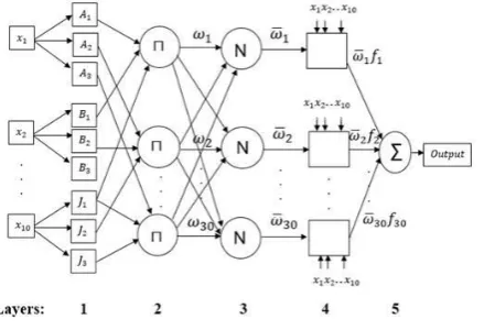
The structure of hybrid neurofuzzy is shown in Figure 2. Neurofuzzy technique gives the fuzzy logic capability to adapt the membership function parameters that best allow the associated fuzzy inference system using properties of neural network to track the given input/output data. The hybrid Neurofuzzy is based mainly on Takagi and Sugeno system. It is used to design the fuzzy inference system with given input/output data pairs. Consider a first-order Takagi and Sugeno fuzzy inference system which contains rules, inputs variables and one output variable (For simplicity, as shown in Figure 2, and are assumed). The (where rule of this system can be given as
where
Figure 2 shows that the hybrid neurofuzzy system has five layers, like the multilayer neural networks, each layer performs a specific task. The square nodes have adaptable parameters that will be adjusted during the training phase while the circle nodes have fixed parameters. The output of the ith node in the lth layer is denoted by , where every node in the same layer performs the same function.
Fig. 2 The structure of hybrid neurofuzzy system
Layer 1 is called fuzzification layer. The output of this layer is given in the following equation:
where is the membership function of the pth node.
The membership function for can be any appropriate
parameterized membership function, such as the generalized triangle function:
Where are the parameters of membership function, they called premise parameters, that will be adjusted in the training phase of the hybrid neurofuzzy system.
Layer 2 is called rule-antecedent layer. Every node in this layer is a fixed node labeled Π, whose output is the product of all the incoming signals:
Each node output represents the firing strength of a rule. Any other T-norm operators that perform fuzzy AND can be used as the node function in this layer.
Layer 3 is called normalization layer. Every node in this layer is a fixed node labeled N. The ith node calculates the ratio of the ith rule's firing strength to the sum of all rules' firing strengths. The output of this node is given as:
Layer 4 is called de- fuzzification layer. Every node in this layer is an adaptive node with following node function
[image:4.595.320.540.169.319.2]
where (k=1,2,…,K) are the set parameters of the polynomial function, they are called consequent parameters which will be adjusted in the training phase. The kth output of this node is given as
Layer 5 called output layer. The single node in this layer is a fixed node labeled ∑, which computes the overall output as the summation of all incoming signals. The output of this node is given as
The adaptable parameters of hybrid neurofuzzy system { should be modified to
minimize the following performance function:
where P is the total number of training data set and Op the error signal between the desired output of pth data and the actual output of hybrid neurofuzzy system of pth data. Op can be given by
where Tp is the pth desired output and zp is the pth actual output in the hybrid neurofuzzy system model.
To modify the parameters of the hybrid neurofuzzy system model, the steepest descent method as in neural network can be applied to modify the premise parameters { and least square estimate can be applied to adapt the consequent parameters { as describe in [30].
6.
NUMERICAL SIMULATION AND
RESULTS
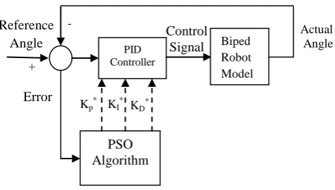
[image:5.595.308.553.87.226.2]In this work, two types of control system are used for biped robot: auto-tuned PID controller and Neurofuzzy controller. The MATLAB program is used to simulate the proposed controller with biped robot and to plot the output responses of four angles. The Simulation parameters for the biped robot are tabulated in Table 1. Four auto-tuned PID controllers are designed one for each angle. The parameters of PID controllers are tuned using Particle Swarm Optimization (PSO) algorithm as shown in Figure 3.
Table 1 The Simulation parameters of the biped robot model
Body parts Length(m) Mass(kg)
Legs l1=l5 =0.8 m1=m5 = 5
Thighs l2=l4 =0.5 m2=m4 =5
Torso l3 =0.5 m3 =1
Fig. 3 Tuned the Parameters of PID Controllers with PSO
The output control signals of PID controllers are applied as voltage inputs for the servo motors to force the join angles to follow the desired trajectories. The first PID controller is designed to control the value of the torso angle (θ3). The second PID controller is design to adjust the difference between the thigh angles (Ω= θ4- θ2). While the third and fourth PID controllers are designed to control the left leg knee angle (θ1) and the right leg knee angle (θ5) respectively. The optimal parameters of PID controllers are shown in Table 2.
Table 2 The parameters of designed PID controllers using PSO algorithm
PID controller Kp KI KD
First PID
Controller 1.562 0.013 4.377
Second PID
Controller 1.683 0.024 0.332
Third PID
Controller 9.773 0.033 1.002
Fourth PID
Controller 67.424 0.021 12.689
The inputs-outputs data set which are collected from the PID controller are used to train the parameters of four Neurofuzzy controllers. Each Neurofuzzy model has two inputs and one output. The first input is the error between the reference angle input and the value of actual angle while the second input is the derivative of the error. Each input has seven Bell-Shape membership functions. First input and second input has seven grades: negative big (NB), negative medium (NM), negative small (NS), zero (ZE), positive small (PS), positive medium (PM) and positive big (PB). The Sugeno-Type fuzzy inference system has been used. The linear function has been used as output membership function. The output of each controller is the voltage control signals with is applied for the servo motor. It has seven grades: negative big (NB), negative medium (NM), negative small (NS), zero (ZE), positive small (PS), positive medium (PM) and positive big (PB). The numbers of fuzzy rules are 49. The selection of this rule depends on the response of the optimal PID controller which is designed before. The Hybrid Learning algorithm has been used to select the optimal values for each Neurofuzzy controller. Also, the output gains of Neurofuzzy controllers (four Neurofuzzy controllers are used in this work) are selected using PSO
PID Controller
Biped Robot Model
PSO Algorithm
Kp* KI* KD*
Reference Angle
Actual Angle
Control Signal
Error
Signal +
[image:5.595.47.289.643.732.2]algorithm. The parameters values of output gains are listed in the Table 3.
Table 3 Output gains values ofNeurofuzzy Controller
Output gain of
First controller
Second controller
Third controller
Fourth controller
97.5382 29.9051 58.0021 73.552 97.5382
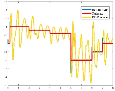
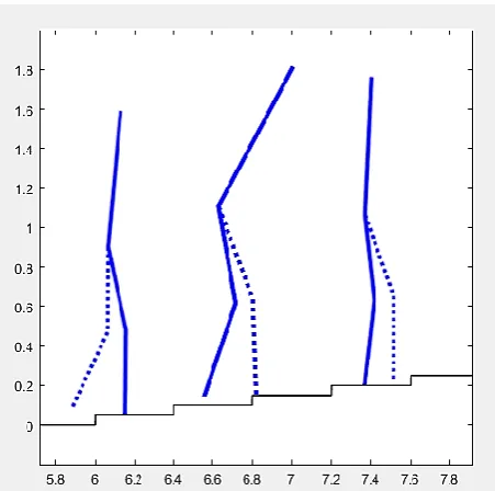
[image:6.595.332.523.82.232.2]The comparisons between the responses of biped model system with Neurofuzzy controller and PID controller to multi step reference are shown in Figure 4-7.
[image:6.595.63.269.205.720.2]Fig. 4 Torso angle response for both proposed controllers
Fig. 5 Difference between the thigh angle response for both proposed controllers
Fig. 6 Left leg knee angle response for both proposed controllers
Fig. 7 Right leg knee angle response for both proposed controllers
7.
WALKING SIMULATION
To study the effeteness of the designed Neurofuzzy controllers, the GUI simulation is used to show the movement of the biped robot on smooth lane as illustrated in Figure 8.
Fig. 8 GUI simulation shows the movement of the biped robot on smooth lane
[image:6.595.73.264.216.364.2] [image:6.595.316.543.324.551.2]Figure 9 GUI simulation movement of the biped robot on rough terrain with random road profile
Figure 10 GUI simulation of climbing of the biped robot the uniform stairs
8.
CONCLUSION
The model of biped robot is highly nonlinear system with various uncertainties, so that the design of robust controller should be established. In this work, two type of controller are designed: Neurofuzzy controller and PID controller. Four PID controllers are designed using PSO algorithm for biped robot to imitate the human locomotion. The input/output data which are collected from PID controller are used to design the Neurofuzzy controller. Then, the output gains of Neurofuzzy controllers (four Neurofuzzy controllers are used in this work) are selected using PSO algorithm. The numerical simulations and results are shown that the proposed Neurofuzzy controllers are able to drive the biped robot to imitate the walking of the human being. The robustness of the proposed controller is studied to show the ability of biped robot to walk on rough terrain with random road profile and climb the uniform stairs look like the human being without falling
down. Also, the results show the robustness and effectiveness of the proposed controller. The GUI simulation is used to prove and illustrate the robustness of the designed controllers. The real implementation of the biped robot with proposed system will be constructed in the future.
9.
REFERENCES
[1] Bowman Chow, C.K and Jacobson (1972) Further Studies of Human Locomotion: Postural Stability and Control. Math. Biosci., 15: pp. 93-108.
[2] Hemami, H., Wil, C. and Goliday, G. L. (1977) The inverted Pendulm and biped Stability. Math. Biosci., 34: pp.95-110.
[3] Miura, H. and Shinoyama, I. (1984) Control of a Dynamic biped locomotion System for Steady Walking. ASME J. Dyn. Syst. Meas. Control, 108: pp. 111-118. [4] Moosavian S. A., Alghooneh M. and Takhmar A. (2007)
Fuzzy Regulated Sliding Mode Control of a Biped Robot. IEEE: pp. 471-476.
[5] Lee H. and Hwang C. (2012) Design by Applying Fuzzy Control Technology to Achieve Biped Robots with Fast and Stable Footstep. IEEE International Conference on Systems, Man, and Cybernetics, October 14-17, 2012, COEX, Seoul, Korea: pp. 1575-1580.
[6] Farzadpour F. and Danesh M. (2012) A new hybrid intelligent control algorithm for a seven-link biped walking robot. Journal of Vibration and Control, pp. 1-16.
[7] M. King, B. Zhu, and S. Tang, “Optimal path planning,” Mobile Robots, vol. 8, no. 2, pp. 520-531, March 2001. [8] Rahmani M., Ghanbari A. and Ettefagh M. M. (2016) A
novel adaptive neural network integral sliding-mode control of a biped robot using bat algorithm. Journal of Vibration and Control, pp. 1-16.
[9] Bowling A. (2010) Impact forces and agility in legged robot locomotion. Journal of Vibration and Control 17(3): 335–346 17(3): 335–346.
[10]Guang Z Zu, Hiroshi K and Kunikatsu T (2006) Adaptive running of a quadruped robot using forced vibration and synchronization. Journal of Vibration and Control 12(12): 1361–1383
[11]Mu X. and Wu Q. (2004) Dynamic Modeling and Sliding Mode Control of a Five-Link Biped during the Double Support Phase. Proceeding of the 2004 American Control Conference, Boston, Massachusetts June 30- July 2, 2004: pp. 2609-2614.
[12]Tzafestas S., Raibert M. and Tzafestas C. (1996) Robust Sliding-mode Control Applied to a 5-Link Biped Robot. Journal of Intelligent and Robotic Systems. 15: pp. 67-133.
[13]Kim C. H., Yu S. J., Park J. B. and Choi Y. H. (2005) Sliding Mode Control of 5-link Biped Robot Using Wavelet Neural Network. ICCAS2005 June 2-5, KINTEX, Gyeonggi-Do, Korea.
[image:7.595.54.280.327.551.2][15]Tabar A. F., Khoogar A. R. and Fakharzadegan M. J. (2007) Controlling a New Biped Robot Model Since Walking Using Neural Network. Proceedings of the 2007 IEEE International Conference on Integration Technology March 20 - 24, 2007, Shenzhen, China, pp.725- 730.
[16]Zaidi A., Rokbani N. and Alimi A. M. (2008) A Hierarchical fuzzy controller for a biped robot. International Conference on Individual and Collective Behaviors in Robotics, pp. 126- 129.
[17]Wongsuwarn H. and Laowattana D. (2013) Neuro-Fuzzy Algorithm for a Biped Robotic System. International Journal of Computer, Electrical, Automation, Control and Information Engineering, 2 (3): pp. 859- 864. [18]J. Kennedy and R.C Eberhart (1995) Particles Swarm
Optimization. Proc. IEEE International Conference on Neural Networks, Perth Australia, IEEE Service Center, Piscataway, NJ, IV:1942-1948.
[19]Y. Shi and R. Eberhart (1998) Parameter Selection in Particle Swarm Optimisation. Proc.-7th Annual Conference on Evolutionary Programming, pp. 591-601 [20]Z. L. Gaing (2004) A Particle Swarm Optimization
Approach for Optimum Design of PID Controller in AVR System. IEEE Transactions On Energy Conversion,19 (2): pp. 284-291.
[21]R. ÇOBAN, Ö. ERÇIN , (2012) Multi-objective Bees Algorithm to Optimal Tuning of PID Controller. Cukurova University Journal of the Faculty of Engineering and Architecture, 27 (2):pp.13-26.
[22]W. Liao, Y. Hu and H. Wang (2014) Optimization of PID control for DC motor based on artificial bee colony algorithm. IEEE International Conference on Advanced Mechatronic Systems, pp. 23-27.
[23]Y. Sonmez1, O. Ayyildiz, H. T. Kahraman, U. Guvenc, S. Duman (2015) Improvement of Buck Converter Performance Using Artificial Bee Colony Optimized-PID Controller. Journal of Automation and Control Engineering, 3 (4): pp. 304-310.
[24]E. A. Ebrahim, (2014) Artificial Bee Colony-Based Design of Optimal On-Line Self- using PID Controller Fed AC Drives. International Journal of Engineering Research, 3(12): pp. 807-811.
[25]G. Yan, C. Li, (2011) An effective refinement artificial bee colony optimization algorithm based on chaotic search and application for PID control tuning. Journal of Computational Information Systems, 7 (9): pp.3309-3316.
[26]E. Turanoglu, E. Ozceylan, M. S. Kiran, (2011) Particle swarm optimization and artificial bee colony approaches to optimize of single input-output fuzzy membership functions. Proceedings of the 41st International Conference on Computers & Industrial Engineering, pp. 542-547.
[27]Kosko B (1992)Neural Networks and Fuzzy Systems. Englewood Cliffs, NJ: Prentice-Hall.
[28]Figueiredo, M., Ballini, S., Soares, S., Andrade, M., and Gomide, F (2004). Learning Algorithm for a Class of Neurofuzzy Network and Application. IEEE Transaction on Systems, Man, and Cybernetics, 34(3), pp.293-301.
[29]Jang, J., and Mizutani, E. (1996) Levenberg-Marquardt Method for ANFIS Learning. Presented at Conference of the North American Fuzzy Information Processing Society NAFIPS, Berkeley, CA, USA.
[30]Jang, R. and Shing, J. (1993) ANFIS: Adaptive Network Based Fuzzy Inference System. IEEE Transaction on System, Man and Cybernetics. 23(3): pp. 665-686
10.
APPENDIX 1
Where
is mass of link, is length of link,
is distance between the mass center of link and its lower joint.
is moment of inertia with respect to an axis passing through the mass center of link and being perpendicular to the motion plane.