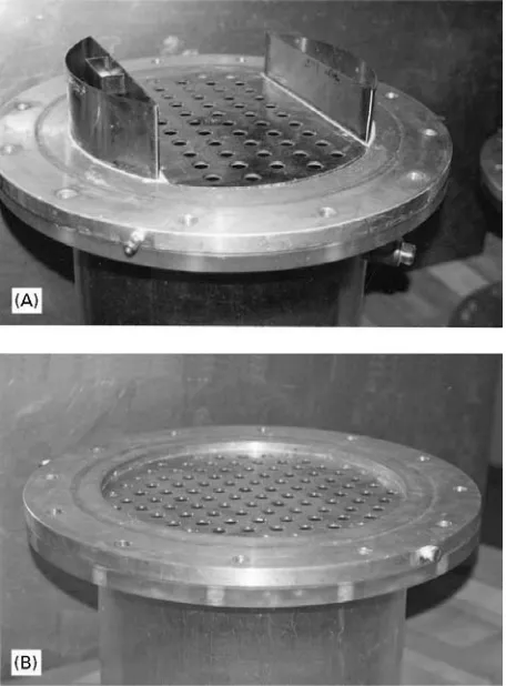
Figure 1 (A) Sieve ray with downcomer in a 30 cm diameter column. (B) Dual-flow tray in a 30 cm diameter column.
Tray Columns: Design
K. T. Chuang and K. Nandakumar,
University of Alberta, Edmonton, Alberta, Canada Copyright^ 2000 Academic Press
Distillation has remained an important separation technology for the chemical process industries. In 1997 it was reported in the journalChemical Engin-eering that about 95% of all worldwide separation processes use this technology. In the USA alone, some 40 000 distillation columns represent a capital invest-ment of about US $8 billion. They consume the en-ergy equivalent of approximately 1 billion barrels of crude oil per day. Such columns are used in reRneries, petrochemical plants, gas processing plants and or-ganic chemical plants to purify natural gas, improve gasoline, produce petrochemicals and organic prod-ucts, recover pollulant species, etc.
Distillation can be carried out in a tray or a packed column. The major considerations involved in the choice of the column type are operating pressure and design reliability. As pressure increases, tray coulmns become more efRcient for mass transfer and can often tolerate the pressure drop across the trays. The design procedure for the large diameter tray column is also more reliable than that for the packed column. Thus, trays are usually selected for large pressurized column applications.
Distillation trays can be classiRed as:
1. cross-Sow trays with downcomers (seeFigure 1A); 2. countercurrent trays without downcomers (also
known as dual-Sow trays) (see Figure 1B).
The-dualSow tray allows the gas and liquid to pass through the same tray openings. This results in a lim-ited operating range because the dispersion height is very sensitive to the gas/liquidSow rates. In general, dual-Sow trays are employed only in cases where high capacity or high resistance to fouling are required. However, because of its narrow operating range, the market share is small and such trays will not be discussed further.
The cross-Sow tray utilizes a weir on the down-comer to control the spray height on the tray, and thus provides a stable gas}liquid dispersion over a wide range of gas/liquidSows. A tray is the combi-nation of a tray deck, where froth is generated to provide vapour}liquid contact, and a downcomer, where the vapour}liquid mixture is separated. The bulk of the vapour rises from the aerated liquid through the vapour disengagement space to the tray above. However, the passage of the liquid from the
top to the bottom of the column occurs mainly via downcomers.
There are three types of cross-Sow trays: (1) sieve, (2) valve and (3) bubble cap. Among them, sieve trays offer high capacity and efRciency, low pressure drop, ease of cleaning, and low capital cost, but smaller turndown ratio. Although the design procedure is similar for all three types of trays, only sieve tray performance data are readily available in the public domain. The valve and bubble cap designs are often protected by patents, and thus the performance data are supplied by the vendors. This article describes the procedure for designing an optimum sieve tray. A similar procedure can be applied in principle to the valve and bubble cap trays, provided critical perfor-mance data are available.
The cost of a tray column is determined by two factors:
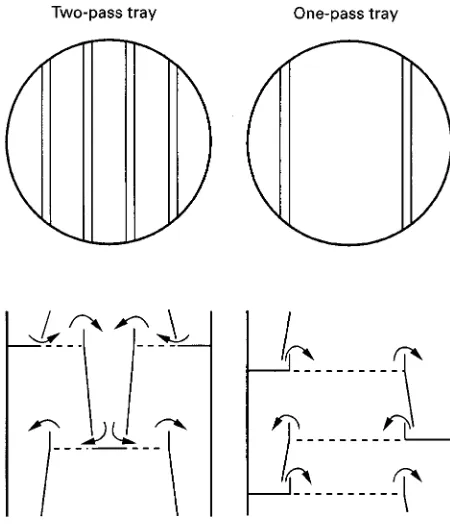
Figure 2 Tray layouts.
2. column height, which delivers the number of equi-librium stages required for the separation.
The minimum cost is generally achieved when the column volume is minimized. The Rnal selection of the tray design is based on the combined cost of the column shell, internals and installation.
It should be noted that the fraction of the cross-sectional area available for vapour}liquid disengage-ment decreases when the downcomer area is in-creased. Thus, optimum design of the tray involves a balance between the tray area and the downcomer area (i.e. the capacity for the tray deck should match the capacity of the downcomer). The correlations for sizing trays are implicit in column diameter, tray spacing and tray geometry, thus requiring trial-and-error calculations to arrive at theRnal selection.
Characteristics of Tray Operation
Typical tray layout is shown in Figure 2, and tray operation is shown inFigure 3. High speed photogra-phy of a large operating tray indicates that the vapour erupts through the liquid sporadically. The holes that are not erupting do not weep appreciably at a vapour rate above the weep point, although the supporting of the liquid by the vapour is not absolutely complete. The interaction of vapour and liquid on a properly designed tray results in a highly turbulent two-phase mixture of a high speciRc interfacial area with net
liquid movement in a crossSow direction to the rising vapour stream. The aerated liquid may be either liquid-continuous (froth) at relatively low vapour vel-ocities or vapour-continuous (spray) at high vapour velocities.
The maximum capacity of a sieve tray is reached when the tray isSooded. This may be due to excessive spraying (entrainment) taking place in the intertray space or the froth in the downcomer backing-up to reach the top of the outlet weir. The onset ofSooding is accompanied by a sharp increase in tray pressure and a sharp decrease in tray efRciency.
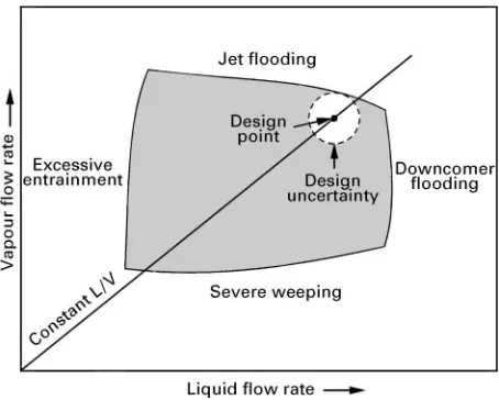
As vapour rates decrease to the point that the vapourSow cannot totally support the liquid on the tray, some liquid will weep through the holes. If the weepage is so severe that no liquidSows over the outlet weir, the tray cannot operate stably under these dumping conditions. The minimum capacity of the tray is normally reached when moderate weepage is encountered. Ideally, a sieve tray should operate in the shaded area shown inFigure 4to ensure proper operation.
Tray efRciency can be divided into two compo-nents:
1. point efRciency as determined by the verticalSow of vapour through the froth;
2. tray efRciency enhancement by the crossSow of liquid.
The physical properties of the vapour}liquid mix-ture determine the point efRciency, although froth height, which inSuences the gas residence time, also has a signiRcant effect, especially for low efRciency systems. LiquidSow pathlength determines the liquid residence time and the extent of crossSow tray efR -ciency enhancement. Entrainment and weeping de-press tray efRciency by disrupting the concentration proRle in the column. The froth height and the liquid
Sow path are two parameters that are optimized to give maximum tray efRciency. Other geometric vari-ables, such as open hole area, hole diameter and downcomer arrangement, also affect tray hydraulics and efRciency. The goal for a tray design is to reach maximum tray efRciency without compromising hy-draulic stability.
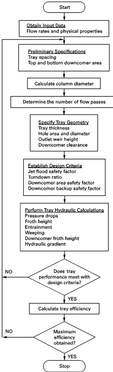
The steps required for tray column design are shown inFigure 5; a detailed discussion of each step is given below.
Input Data
Figure 3 Tray operation schematic diagram.
Figure 4 Sieve tray performance diagram.
well as density, diffusivity andSow rate of the vapour stream. This information can be obtained by per-forming tray-to-tray distillation calculations; several commercial computer packages are available for this purpose (e.g. PRO II, ASPEN PLUS, HYSIM).
As the physical properties and the vapour and liquidSow rates vary throughout a given column, it is difRcult to provide a single design for the entire col-umn. Instead, the column is divided into a number of sections. Within each section, trays are designed with the same layout. Normally the section is a set of trays bounded by two column penetrations (feed and/or drawoff). Tray design calculations should be performed to ensure that trays at the top and bottom of the section meet the design require-ments.
Preliminary Speci
\
cations
Tray Spacing
Tray spacing is set by maintenance requirements, and also by support structure design in large-diameter columns. SufRcient crawl space must be provided for tray cleaning and repair. From these considerations, the minimum tray spacing is about 12 in (30 cm) for column diameter less than 5 ft, and (150cm) and 18 in (45 cm) for a column diameter greater than 10 ft (300 cm). In general, it is best to keep tray spacing to a minimum, which is often the most econ-omical.
Downcomer Area
The downcomer area at the top is sized such that the velocity of the ascending vapour bubbles exceeds the downSow velocity of the liquid. The size is related to
the stability of the froth in the downcomer and deter-mined by the residence time required for achieving the separation of the two-phase mixture. For non-foaming systems, such as lower alcohols, a residence time of 3 s is sufRcient, whereas for extremely high foaming systems such as caustic regenerators, 9 s is required.
To prevent the liquid coming off the bubbling area from splashing against the column wall, the minimum downcomer width is 5 in (12.7 cm). Also, the min-imum side chord length should be 60%of the column diameter. This is required to maintain good liquid distribution on the tray.
[image:3.568.291.518.515.697.2]Figure 5 Sieve tray design procedure.
It should be noted that the downcomer area occu-pies only a small fraction of the cross-sectional area. Thus, a small overdesign does not result in a signiR -cant economic penalty.
Column Diameter
The column diameter can be calculated once the tray spacing and downcomer area have been speciRed. The Fair correlation, based on the Souders and Brown criterion, is recommended by most designers. The vapour Sooding velocity can be calculated from eqn [1].
UN,f"CSB
L!V
V
0.5 L20
0.2
[1]
In eqn [1] CSB is the Souders}Brown coefRcient,
LandL(dyne cm\1) are liquid density and surface
tension, respectively, andVis the vapour density in
the same units asL. UN,f is based on the net area, AN(ft2), which is the active area plus one downcomer
area. The unit for UN,f is ft s\1. The most popular
empirical formula for calculating CSB is given in
eqn [2].
CSB(ft s\1)"0.04232#0.1674TS
#(0.0063!0.2686TS)FlV
#(0.1448TS!0.008)F2lV [2]
In this equationFlV"(L/V)(V/L)0.5,TSis tray
spac-ing in feet, andL and Vare mass Sow rates of the liquid and vapour. The CSB is valid for trays with
a fractional hole area greater than 10%. For areas of 8%and 6%,CSBshould be multiplied by 0.9 and 0.8,
respectively.
KnowingUN,fand the total vapourSow rate, the
column diameter can be calculated by assuming that the column will be operated at a lower vapour velo-city, say 80%of theSood point.
Number of Flow Passes
[image:4.568.65.259.58.693.2]As a rule of thumb, the liquid and vapour handling capacity are a direct function of weir loading and column area, respectively. Since weir length and col-umn area are proportional to colcol-umn diameter and diameter squared, respectively, the use of multipass trays is often necessary for large-diameter columns.
Tray Geometry
Tray geometry should be chosen so that hydraulic and efRciency calculations can be performed to arrive at the optimum design. The following parameters must be speciRed for tray design calculations.
Tray Thickness
The choice of material for the fabrication of trays is dependent mainly on the corrosion properties of the process Suids. In general, tray thickness is about gauge 10 (0.134 in; 3.40 mm) for carbon steel and gauge 12 (0.109 in; 2.77 mm) for stainless steel. For economic reasons the holes are punched, which dic-tates that the thickness must be less than the hole diameter.
Hole Diameter
Small holes with a diameter in the range of 3 16to14in
(4.76}6.35 mm) give better hydraulic and mass trans-fer performance than the large ones in the range of1 2
to 3
4in (12.7}19.0 mm). However, large-hole trays
are cheaper and show more resistance to fouling. Choose the hole size according to design require-ments.
Hole Area
The hole area is normally in the range of 5}16%of the bubbling area. Lower hole area allows the tray to operate at higher efRciency and turndown ratio, but at the expense of higher pressure drop. Since the operating pressure of the column dictates the max-imum allowable pressure drop, the hole area is se-lected according to the type of service. Recommended values are 5}10%for pressure and 10}16%for vac-uum operations.
Hole areas below 5% are not used because the distance between holes becomes excessive and liquid channelling may occur. However, the distance can also be adjusted by changing the hole diameter. In general, the hole pitch should not be larger than 2.5 in (6.35 cm). On the other hand, if the hole areas are greater than 16%, signiRcant weeping and en-trainment may coexist and the design equations may not apply under these conditions.
Weir Design
Outlet weirs are used to control the froth height on the tray. For most trays, the outlet weir height is about 1}4 in (2.5}10 cm) and the downcomer clear-ance, where the liquid is discharged from the bottom of the downcomer onto the tray below, should be 0.5 in (1.25 cm) smaller than the outlet weir height to ensure a positive downcomer seal.
From the above discussion, it may be concluded that the object of tray design is to obtain the optimum combination of the following parameters:
1. column diameter 2. tray spacing
3. top and bottom downcomer area 4. hole diameter and hole area
5. outlet weir height and downcomer clearance.
Design Criteria
The trays should be designed for maximum through-put. However, owing to inaccuracies in the design equations andSuctuation of process conditions (e.g.
Sow rates, temperature and pressure), safety factors are needed to ensure stable column operation at all times (see Figure 4).
Jet Flood Safety Factor
The jetSood safety factor (JFSF) is deRned as the ratio of vapour velocity required to entrain the entire liquid
Sow (Umax) to the operating velocity (Uop). It is a
use-ful measure of entrainment and hydraulic stability. The typical JFSF value is 1.2.
Turndown Ratio
For various reasons, the column may be operated at a reduced throughput. Weeping is encountered if the vapour velocity can no longer support the liquid on the tray. AlthoughSow dynamics permit stable op-eration as long as dumping is avoided, tray efRciency suffers because weeping reduces the vapour}liquid contact. The turndown ratio is the ratio of the design vapourSow rate to theSow rate that permits some weeping without seriously affecting the tray efR cien-cy. Recommended weepages at turndown conditions for vacuum and pressure operations are 3%and 7%, respectively.
Downcomer Area Safety Factor (DCASF)
and Downcomer Backup Safety Factor (DCBUSF)
to the minimum area to the minimum area required for vapour}liquid disengagement. The DCBUSF de-termines the approach of the downcomer froth height to the downcomer depth ("tray spacing#outlet weir height). Safety factors in the range of 1.5}2.0 are recommended.
Pressure Drop
The pressure drop across an operating tray should be speciRed if it affects the number of equilibrium stage requirements for the separation. This is often the case for vacuum applications. Stable operation can be obtained at a pressure drop of 1}3 in (2.5}7.6 cm) of liquid per tray for vacuum and 2}5 in (5.1}12.7 cm) for pressure operations.
Design Calculations
Tray Hydraulics
The hydraulic performance of a sieve tray for a given layout may be calculated using the methods presented in ‘Distillation/Tray Columns: Performance’.
Tray Ef\ciency
Tray efRciency is a strong function of the physical properties of the vapour and liquid streams. It is also affected, to a lesser extent, by theSow rates and tray layout. In the latter case, only hole diameter, hole area and weir height have a small inSuence on the tray efRciency. The optimum design, which gives the maximum number of equilibrium stages in a column, is often obtained at minimum tray spacing and min-imum number ofSow paths that satisfy the hydraulic design criteria.
Conclusions
A well-designed tray should be economical while meeting all process design requirements. Economic
considerations suggest that it is best to use the smallest column diameter and height that satisfy the process requirements within reasonable safety allow-ances. Process requirements include accommodation of the expected liquid and vapourSow ranges and the optimization of tray efRciency.
See also: II/Distillation: Packed Columns: Design and Performance; Theory of Distillation; Tray Columns: Perfor-mance.
Further Reading
Billet R (1979)Distillation Engineering. New York: Chem-ical Publishing Co.
Fair JR (1963) In: Smith BD (ed.)Design of Equilibrium Stage Processes. New York: McGraw-Hill.
Fair JR (1987) In: Rousseau RW (ed.) Handbook of Separation Process Technology, ch. 5. New York: John Wiley.
Fair JR, Steinmeyer DE, Peuney WR and Crocker BB (1997). In: Perry RH and Green D (eds)Perry’s Chem-ical Engineers’ Handbook, 7th edn, sect. 14. New York: McGraw-Hill.
Humphrey JL and Keller GE II (1997)Separation Process Technology. New York: McGraw-Hill.
Kister HZ, (1992) Distillation Design. New York McGraw-Hill.
Lockett MJ (1986)Distillation Tray Fundamentals. Cam-bridge: Cambridge University Press.
Lygeros AI and Magoulas KG (1986) Column Sooding and entrainment. Hydrocarbon Processing 65: 43}44.
McCabe WL, Smith JC and Harriott P (1993)Unit Opera-tions of Chemical Engineering, 5th edn. New York: McGraw-Hill.
Ogboja O and Kuye A (1991) A procedure for the design and optimization of sieve trays. Transactions of the Institution of Chemical Engineers445.
Rose LM (1985)Distillation Design in Practice. Amster-dam: Elsevier.
Tray Columns: Performance
K. Nandakumar and K. T. Chuang, University of Alberta, Edmonton, Alberta, Canada
Copyright^ 2000 Academic Press
Introduction
As pointed out in the article entitled distillation tray columns: design, a sieve tray is designed with a