EvoBot: An Open-Source, Modular Liquid Handling Robot for Nurturing
Microbial Fuel Cells
A. Fa´ı˜na
1,3, F. Nejatimoharrami
1, K. Stoy
1, P. Theodosiou
2, B. Taylor
2and I. Ieropoulos
21Robots, Evolution, and Art Lab (REAL), IT University of Copenhagen, Denmark
2Bristol BioEnergy Centre, Bristol Robotics Laboratory, University of the West of England, Bristol, UK 3Corresponding author: [email protected]
Abstract
Liquid handling robots are rarely used in the domain of artificial life. In this field, transitory behaviours of non-equilibrium man-made systems are studied and need an au-tomatic monitoring and logging of results. In addition, ar-tificial life experiments are dynamic with frequent changes, which makes it difficult to apply conventional liquid handling robots as they are designed to automate a pre-defined task. In order to address these issues, we have developed an open source liquid handling robot, EvoBot. It uses a modular ap-proach, which gives us the possibility to reconfigure the robot for different experiments and make it possible for users to add functionality by just developing a function specific mod-ule. In addition, it provides sensors and extra functionality for monitoring an experiment, which allows researchers to perform interactive experiments with the aim of prolonging non-equilibrium conditions. In this paper, we describe the modular design of EvoBot, document its performance, and provide a novel example of an interactive experiment in arti-ficial life, where the robot nurtures a microbial fuel cell based on its voltage output.
Introduction
Liquid handling robots are often employed in chemical and biochemical laboratories in order to automate repetitive tasks (see (Kong et al., 2012) for a useful overview of liquid handling robots for lab automation). The benefit of this is typically an increase in reliability, throughput and precision when compared to manual liquid handling coupled with a reduction in labour cost. However, liquid handling robots are rarely used in the domain of artificial life.
There are two types of challenges that make existing liq-uid handling robots inappropriate for experiments in artifi-cial life. The first relates to the functionality needed from the robot to be useful in artificial life research. In artificial life we are mostly interested in the initial condition of an experiment and how it develops but not typically in the end result, because the end result is equilibrium which in the context of artificial life corresponds to death. This means that not only should the robot prepare experiments, but also employ automatic monitoring and logging of results. Fur-thermore, it would be desirable if the liquid handling robot,
based on this monitoring, can interact with the experiment to extend its life-time. Solving this challenge has been the ba-sis for the results of (Gutierrez, 2012; Gutierrez et al., 2014; Hanczyc et al., 2015; M¨uller et al., 2015), who all made an ad-hoc liquid handling robot for specific experiments in ar-tificial chemical life.
The second type of challenge, which is the focus of our work, is the practical challenge of employing liquid han-dling robots in artificial life research. Artificial life research is often performed in small, government funded labs and as such the cost of acquisition is a limiting factor. Artificial life experiments are not static, but develop in response to the insights obtained from the experiments and this makes it difficult to apply conventional liquid handling robots as re-programming and reconfiguration is often tedious and time-consuming if at all possible for the end user. Furthermore, conventional liquid handling robots are often only setup to perform one specific task, thus making it difficult to modify with functionalities required for new types of experiments. If we could provide solutions to these challenges, artificial life research could also benefit from the advantages of au-tomation namely increased reliability, throughput, precision and reduced cost. Turning these challenges around we are looking for liquid handling robot technology that has the fol-lowing characteristics:
• Reconfigurable
• Versatile
• Low cost
• Extendable
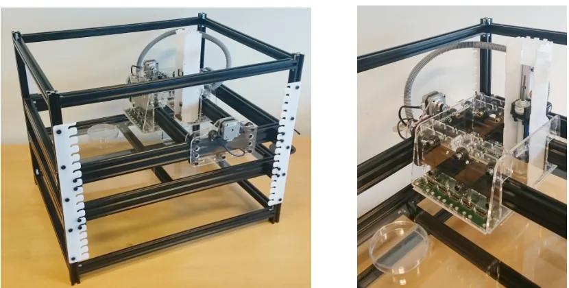
Figure 1: The EvoBot liquid handling robot (left) and a close-up of the movable head equipped with one syringe module.
during their life-time. We have made EvoBot open-source, which reduces the cost of acquisition and also allows re-searchers to build on our reliable platform and extend it with modules that have the necessary functionality for their spe-cific experiment1.
In this paper we present the modular design of the liq-uid handling robot, EvoBot, and carefully document its per-formance to make it possible for potential users to evaluate how appropriate it is for their experiment. We have already demonstrated its usefulness in artificial chemical life (Ne-jatimoharrami et al., 2016), but here we further evaluate its use in a new application domain, nurturing microbial fuel cells (MFCs). MFCs are devices where microbes convert organic matter directly into electricity. MFCs have demon-strated their utility as a basis for building robots with an ar-tificial metabolism (Ieropoulos et al., 2010).
The conclusion is that EvoBot due to its versatility, ex-tendability, and low cost was successfully implemented in the new application domain of nurturing microbial fuel cells with very limited modification. It is also demonstrated that using the robot for maintaining microbial fuel cells, com-pared to manually nurturing them, has numerous advan-tages, and thus in time may provide insights that can help researchers develop more efficient microbial fuel cells.
EvoBot Design Principles
As outlined above, a key goal of the EvoBot design was to develop a robotic platform, which can be configured for a
1
Source code and design files can be found in Git repositories, https://bitbucket.org/afaina/ evobliss-software and https://bitbucket.org/ afaina/evobliss-hardwarerespectively.
wide range of experiments without the involvement of an expert user. In order to achieve this, we modularised the design building on research in the field of modular robotics (Yim et al., 2007). A modular approach allows us to en-capsulate complexity while providing a simple mechatronics plug’n’play interface to the system.
EvoBot (see Figure 1) consists of one structural frame and three types of layers, which in the default configura-tion are organised as follows: the top layer carries actuaconfigura-tion, the middle layer is the experimental section, and the bottom layer is an observation platform. However, this default lay-out can easily be amended, e.g. several experimental layers can be introduced if a cascading experiment is under investi-gation. These three layers can easily be moved up and down in the frame. Functionality is provided in the form of mod-ules, which allow functionality to be added incrementally in the form of new modules.
EvoBot Implementation
In the following section, we will provide an overview of the hardware (mechanics & electronics), and software of EvoBot.
Mechanics
First, we will describe the layers of EvoBot in more detail followed by the implementation of the modules.
Frame The frame is made of aluminium profiles and it
provides the physical support for the layers. They can be attached to the frame at specific heights every 20mm. Ad-ditionally, it allows levelling the robot with four adjustable feet. The frame measures 600x400x600mm but it can easily be extended.
Layers The EvoBot platform is organised into three types
of layer: actuation, experiment, and observation layers. The actuation layer contains a head, which can move in the horizontal plane using two belt and pinion mechanisms and two stepper motors. Up to 11 modules can be mounted on this head to provide different functionalities. At this point, only an actuated syringe module and a heavy pay-load module have been implemented, but various actuators and sensor modules are envisaged, e.g. temperature sensor, pH sensor, gripper for manipulation of dishes, extruder for printing reaction vessels, etc.
The experimental layer is essentially just a frame with a glass plate where vessels can be organised as required by the specific experiment. There is a hole in one corner, where vessels can be moved and dropped for automatic disposal, and together with a Petri dish dispenser system under devel-opment, a large number of experiments can be done in se-quence. However, we have found that for now it is enough to clean reaction vessels by going through three water wash cy-cles, where vessels repeatedly are filled with water and emp-tied using the syringe modules. This makes the dispenser functionality less critical for long term operation. However, for more sensitive experiments the vessels and also syringe tips may have to be replaced on a per experiment basis.
The observation layer is essentially the same as the ac-tuation layer except that modules cannot interact physically with the experiments above, because they are shielded by the glass plate. This limits the useful modules for this layer to modules that do not directly manipulate the experiments. Currently, a static webcam is used in the observation layer to monitor the experiment and provide feedback to the robot. However, in the longer term thermal imaging, magnetic stir-ring, liquid effluent sampling or the like could be integrated in modules for the observation layer.
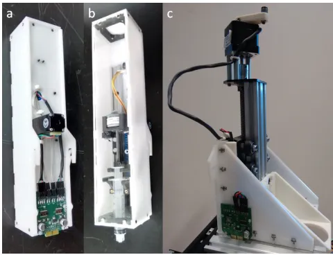
Syringe and Heavy Payload Module The syringe module
[image:3.612.318.558.52.236.2]can be seen in Figure 2.a-b has two degrees of freedom. It has a linear stepper motor (a stepper motor with a lead screw
Figure 2: Syringe module (a, b) and heavy payload module (c).
and an internal nut) for moving the plunger up and down and a rack and pinion mechanism with another stepper motor for moving the syringe up and down. Syringes up to 20ml can be used and they can easily be replaced giving the user the opportunity to use the syringe that matches the experimental requirements.
The heavy payload module is designed to hold and move up and down big and heavy parts. A lead screw mechanism is used to hold the payload even if its motor is switched off. A Nema 17 stepper motor moves the payload but it can also be manually operated with a crank. Its stroke is 80mm and the maximum speed is 8mm/s. This module is shown in Figure 2.c and its end effector is designed to hold an OCT scanner, but it can easily be modified to hold other devices.
More modules are under development including a mod-ule with a gripper, and a modmod-ule to measure pH. However, an EvoBot with one syringe is enough to perform useful experi-ments in artificial chemical life as demonstrated in (Hanczyc et al., 2015; Gutierrez et al., 2014).
Electronics
con-sists only of simple routing, two input/output port expanders with serial interface (I2C) and spring connectors. For the modules, a custom board was also made that contains two stepper drivers with SPI communications (L6470) for mov-ing up and down the stepper motors of the module, see Fig-ure 2.a. When a module is placed on the head, the spring connector touches the pads of the board of the syringe and transmits power and the SPI signals. Furthermore, the wires between the Arduino and the head are reduced using the I2C expander ports as they generate the Chip Select signals for the SPI communication. Using this approach, only a power cable and an 8-way ribbon cable with the I2C and SPI buses are necessary to manage the 22 motors of the 11 syringe modules, which can be placed on the head.
Software
The goal of the software was to provide the end-user with a simple programming interface to the robot. The software has a host side and a robot side. The host side communi-cates with the robot side over a serial USB connection and the robot side software is a modified version of the Marlin firmware used in open-source 3D printers.
On the host side, we have chosen Python as the implemen-tation language as this was the language with which our col-laborators have most experience and also due to its simplic-ity. The software is divided into a graphical user-interface for manual control of the robot and a simple application pro-gramming interface.
Robot Manual Control The purpose of the manual
con-trol graphical user interface is simply to be able to test var-ious functions of the robot without having to resort to pro-gramming. However, the most important use of the manual control program is to learn the position of interesting ob-jects in the robots coordination frame. For example, the user could move the robot until it is approximately in the centre of a Petri dish of interest and lower the syringe so the tip is in the vessel. This is an empirical way of defining the geom-etry for an experiment, and perhaps the most practical for a range of experiments.
Application Programming Interface The application
programming interface is also kept as simple as possible. The interface gives the programmer access to moving the robot head, moving the syringes and plungers, and inquiring about the positions of these elements.
The application programming interface is built on top of printcore, which is an open source Python library for in-teracting with 3D printers and pySerial, which handles the serial communication. The printcore library, however, has been heavily reduced and is likely to be unnecessary in the near future.
[image:4.612.335.543.76.158.2]At the bottom of the software stack we have implemented a basic simulation that can be swapped instead of the se-rial communication library. This makes it possible to debug
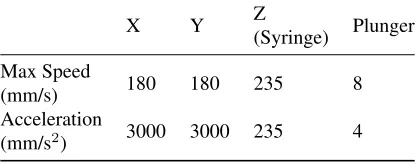
Table 1: Max speed and accelerations of the robot.
X Y Z
(Syringe) Plunger
Max Speed
(mm/s) 180 180 235 8
Acceleration
(mm/s2) 3000 3000 235 4
the upper layers without actually moving the physical robot. This is a feature that has saved a significant amount of de-velopment time.
Marlin-Based Firmware On the robot side we run an
ex-tended version of Marlin, a firmware used to control open-source 3D printers. This gives us a mature basis for our robot controller. The head of the actuation layer is controlled di-rectly using the functionality Marlin provides. For the sy-ringe or heavy payload modules, we have extended Marlin with G-code commands for interacting with them. The use of Marlin is also beneficial as it is our plan to make an ex-truder module, which can 3D print reaction vessels and thus this aspect of the firmware can also be put to good use.
Precision and Performance
For the reader interested in understanding if EvoBot is suit-able for their experiments and to facilitate comparison be-tween liquid handling robots, we provide below a careful investigation of the precision and performance of EvoBot.
Speed
A key parameter to perform experiments is the speed of the robot because the experiments could take a long time if the speed of the robot is low or it is not able to manage a set of tests simultaneously. With this objective in mind, the max-imum speed of the robot was tested for each axis. The test consisted of movements on each axis, increasing its acceler-ation and maximum speed until the robot lost some steps. In other words, the maximum speed is when the positioning of the robot after several movements is not accurate anymore. Table 1 contains the results of these tests and displays that they are significantly higher than the requested accuracy by our collaborators.
Positioning Performance
Table 2: Positioning accuracy for each axis of the robot.
0mm 1mm 2mm 10mm 20mm
X
(mm) 0.04 0.03 -0.04 -0.11 -0.17 Y
(mm) 0.01 -0.05 -0.08 -0.14 -0.18 Z
[image:5.612.68.279.74.169.2](mm) 0.10 0.02 0.09 0.28 0.35
Table 3: Repeatability for each axis of the robot.
X Y Z
RP (mm) 0.067 0.013 0.106
Accuracy is simply defined asA = ¯q−qt, whereqt is
the target position andq¯is the average of n measured coor-dinates. In this test, the robot was homed, and the dial indi-cator was placed in contact with the probe and set to zero. Then, the robot moved one axis sequentially to five different positions (1, 2, 10, 20 and 0 mm) and the real position of the probe was measured. This sequence was repeated 30 times and the accuracy for each point was calculated. The data is shown in Table 2, where we can observe that the position-ing is quite reasonable for a low cost machine and there is no noticeable discrepancy. Furthermore, the slow increment of the inaccuracy when moving the robot to 10 and 20mm is mainly caused by a misalignment between the axis of the indicator and the axis of the robot. This is confirmed by moving the robot to longer distances where we do not detect any appreciable error. In the future, we will employ com-puter vision technology to calibrate the positioning accuracy measuring the three axes at the same time.
Regarding the repeatability or precision of the robot, we ran another experiment. Thus, five points were defined all along the workspace of the robot and the robot moved the probe sequentially from one point to the next one. At the last point, the end effector touched a dial indicator to mea-sure its coordinates. This sequence was repeated 30 times for each axis and repeatability was calculated using Equa-tion 1, where q are the measurements,q¯is the average of these measurements, n the number of trials, S the standard deviation. Table 3 shows the repeatability for each axis. Re-sults display very good repeatability in the three axis, around or less than 0.1mm.
RP = 3Sq = 3 s
Pn
i=1(qi−q¯)2
n−1 (1)
Liquid Handling Performance
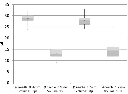
In order to measure the precision and accuracy of handling droplets, we performed various experiments with different
0 5 10 15 20 25 30 35
Ø needle: 0.96mm Volume: 30µl
Ø needle: 0.96mm Volume: 15µl
Ø needle: 1.7mm Volume: 30µl
Ø needle: 1.7mm Volume: 15µl
µl
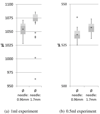
Figure 3: Boxplot comparing experiments with 100µl sy-ringe. The whiskers represent the lowest and highest datum still within 1.5 IQR (interquartile range) of the lower quartile or of the upper quartile, respectively.
syringe sizes, needle diameters and droplet volumes. The experiment was to absorb distilled water from a Petri dish and dispense it over a scale with ±0.003g precision, and therefore obtaining droplet volume by the mass-volume rela-tion. Four experiments were performed with a professional 100µl syringe (Hamilton 710 LT) to handle liquid volumes of 15µl and 30µl , with needle internal diameters of 0.96mm and 1.7mm. To obtain better results in these experiments, a small quantity of air was taken into the syringe prior to ab-sorbing water. Four other experiments were performed with a cheap disposable 5ml syringe (Braun Omnifix) to handle liquid volumes of 1ml and 0.5ml. In these experiments, the needle internal diameters were 0.96mm and 1.7mm. Each experiment was run 30 times.
950 975 1000 1025 1050 1075 1100
Ø needle: 0.96mm
Ø needle: 1.7mm
µl
(a) 1ml experiment
500 525 550
Ø needle: 0.96mm
Ø needle: 1.7mm
µl
[image:6.612.68.277.62.299.2](b) 0.5ml experiment
Figure 4: Boxplot comparing experiments with 5ml syringe. The whiskers represent the lowest and highest datum still within 1.5 IQR of the lower quartile or of the upper quartile, respectively.
in future work. Some alternatives could be to increase the speed of the plunger while dispensing the liquid, to generate a small vibration when moving up the syringe quickly or to use pipettes with low surface tension.
Interactive Feeding of Microbial Fuel Cells
In this experiment we document how we applied EvoBot to the task of maintaining microbial fuel cells (MFCs). The mi-crobial metabolism, utilises the carbon energy source within the anode chamber, which eventually depletes the carbon content and results in decreasing the voltage output from the MFC; in other words, as the fuel runs out, the voltage de-creases. Thus, the robot feeds the MFC with more organic material when the voltage is below a threshold. And as a result of the interaction, the experiment is prolonged.
In order to analyse the advantages of using a liquid han-dling robot, two parallel microbial fuel cell experiments were performed using identical materials and methods with the only difference being that one of them was carried out manually, as a replica (control) experiment, and the other one was carried out by the EvoBot platform (Figure 5). In the case of the robot experiment, the voltage is sampled ev-ery minute, the MFCs are hydrated evev-ery four hours and only fed if the voltage is below the specified threshold. In contrast, the voltage of the replica (on the bench) was sam-pled every three minutes, and the MFCs were hydrated twice a day - morning and afternoon - and fed once every morning.
Microbial Fuel Cell Structure
Nine small-scale, 3D printed from NanocureR resin,
open-to-air cathode MFCs were used in these experiments. The volume of each of the fuel cell anode chambers was 6.25 mL, and the anode and cathode chambers were separated by a single sheet of activated cation exchange membrane, CMI-7000S (Membranes International Inc., Ringwood, USA). Two rubber gaskets, one for each half-cell,sandwichedthe membrane, and ensured watertight sealing, after the two chambers were bolted together using stainless steel studding and nuts.
Electrode Material (Anode and Cathode)
Untreated (catalyst free) carbon fibre veil, with 30g/m2
car-bon loading (PMF Composites, Dorset, U.K.) was used as anode electrode with a total surface area of 168 cm2. The
anode electrode was folded down 5 times, until the projected (exposed) surface area was 5.25 cm2 and could therefore
fit into the anodic chamber (18 mm x 28 mm). The cath-ode electrcath-ode was made of two layers, a gas diffusion layer (GDL) and a Micro-Porous Layer (MPL). The GDL was a single sheet of carbon veil coated with 30% Polytetrafluo-roethylene (PTFE) (Sigma Aldrich, UK). Once GDL cured, activated carbon paste was applied on top to form a thick MPL (1 mm). The activated carbon paste was a mixture of activated carbon powder (G.Baldwins & Co., London, U.K.) blended with PTFE in a 4:1 ratio and deionised water (120 mL). The activated carbon paste was then hot pressed, us-ing a household iron (Gajda et al., 2015), and subsequently heated for 15 minutes to200◦C to allow MPL liquefaction.
Inoculation
For the MFC experiment on the EvoBot platform, the inoc-ulation (i.e. introduction of live microorganisms in a ster-ile MFC) was done using the anolyte from already estab-lished MFCs. This was activated sludge fed with carbon sources such as tryptone yeast-extract (TYE) over a period of months, which had been sieved to remove large particles (>1 mm) so as to prevent blockage of the syringe needle on Evobot. For the replica bench experiment, neat activated sludge supplied by the Wessex Water Scientific Laboratory (Saltford, UK) was used as the initial inoculum. All MFCs in both experiments were kept under a fixed load of 3.9kΩ, for the whole duration.
Experimental software setup
Figure 5: Interactive Feeding of Microbial Fuel Cells. Nine individually connected MFCs were operated with Evobot platform. The experiment took place on the experiment layer of the robot. The replica bench experiment was setup in exactly the same manner.
limit for each MFC was set in LabView where if the voltage dropped below this threshold, then a Python script would activate to move the head of the robot over the food source, draw 3 mL of substrate (carbon fuel) and then inject this into the MFC.
After the feed substrate has been deposited into the anode, the syringe module would go through a wash cycle where 3.5 mL of 70% ethanol was drawn into the syringe and dis-posed of down a waste tube on the Evobot platform, fol-lowed by the taking of 3.5 mL of sterile distilled H2O into
the syringe, before disposing this down a waste tube and then returning the robot head to the home position. At the home position, the feed function paused for 60 minutes to al-low stabilisation of the MFC and for the voltage to increase above the threshold.
A cathode hydration cycle was also incorporated in a sep-arate function in LabView, which activated a Python script every 4 hours. This script moved the robot head over the position of each MFC and deposited 3.12 mL of deionised water into the cathode chamber before returning to the home position.
Although for the Evobot experiments, the ‘wash cycle’ with ethanol and deionised water was deemed necessary, in order to avoid the cross-contamination between the different carbon-energy sources (acetate, lactate and cellulose), this was not necessary for the replica bench experiment, which was carried out manually.
Results
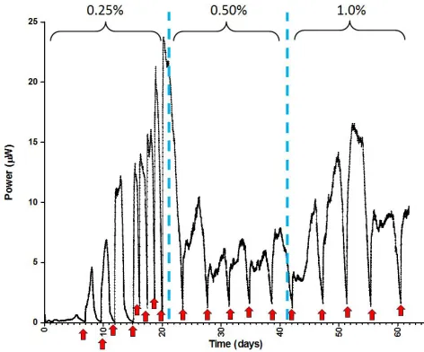
The experiment lasted approximately 8 weeks for the Evobot experiment and 4 weeks for the replica and the comparisons between the experiments are made for the same 4 week pe-riod. The power output of one MFC fed by EvoBot and the feeding events are shown in Figure 6.
[image:7.612.54.295.54.169.2]A significant performance difference was found between the replica experiment and the EvBbot experiment; the replica experiment (data not shown) showed higher power
Figure 6: Power output from one of the MFCs (MFC2) fed by the Evobot with sodium acetate. The red arrows indicate the points where the voltage output of the MFC dropped be-low the 80mV threshold, which was the trigger for feeding the MFC. The dotted lines indicate the periods during which three different concentrations of sodium acetate were tested.
output levels from the MFCs, compared to those from the MFCs on EvoBot. This could have been due to the wash cycle with ethanol, which would have inevitably left resid-ual ethanol in the syringe during the course of the experi-ment - the replica experiexperi-ment did not require a cleaning cy-cle. Also, the sieving of sludge for the inoculation of the MFCs may have well resulted in a less enriched inoculum, and this was done to prevent the syringe needle from block-ing - again, this was not an issue for the parallel bench ex-periment.
Nevertheless, having automated feeding pulses which were dictated by the voltage threshold, the behaviour of a MFC could more closely be monitored ”day or night” in a way that would otherwise require an operator to be continuously present. In addition, the automated hydra-tion cycle was advantageous, since it helped us identify em-pirically the aqueous O2 saturation levels for the
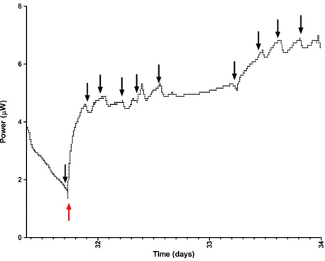
Figure 7: Power output from the same MFC2, following cathode hydrations by Evobot, during one feeding cycle be-tween days 31-34 of the experiment. Black arrows indicate points of EvoBot hydration; the red arrow indicates a point of feeding.
Future Work
We are currently working to address the issues caused by the ‘wash cycle’. A simple option would be to increase the number of times that the syringe is washed with distilled wa-ter, but we are also looking into other different techniques to avoid cross contamination. First, a dispensing module is under development, which uses external pumps to provide pure reagents or solutions. Thus, different organic materials could be used to feed the MFCs without having to use the same syringe. Additionally, we are also starting to use dis-posable pipette tips, but they have to be placed in the syringe manually. We hope to automate the change of these pipette tips in the future.
Regarding the interactive experiments, they are now based on the voltage of the MFCs. However, we are planning to extend the robot with sensing modules for measuring more parameters. As an example, we are developing a pH mod-ule, which will allow us to control the pH of the MFCs by adding acid or alkaline solutions. Our intention is that new interactive experiments will allow us to pose different scien-tific questions, possess novel data never recorded before and help us develop better MFCs.
Conclusions
The EvoBot robot is an open-source, modular liquid han-dling robot. Our design focuses on high quality, relying on open-source components and software, and being eas-ily reconfigurable and extendable. Thus, EvoBot provides a versatile and low cost tool to carry out research in multiple fields. We have in this paper described the overall imple-mentation of the mechanical structure consisting of layers
and modules and documented the performance of the robot, which are easily within the parameters required for a wide range of liquid-based experiments. In particular, a novel ex-periment with MFCs has been carried out, where the robot nurtures interactively an MFC based on its voltage. We hope that the unique features of this platform can form the basis for new lines of research in artificial life.
Acknowledgments
The authors would like to thank the E.U. Future and Emerg-ing Technologies who supported this work through EVOB-LISS grant no. 611640 and the members of the EVOBEVOB-LISS consortium. In particular, Martin Hanczyc and Juan Manual Parrilla Guti´errez, who were heavily involved in developing the concept.
References
Gajda, I., Greenman, J., Melhuish, C., and Ieropoulos, I. (2015). Simultaneous electricity generation and microbially-assisted electrosynthesis in ceramic mfcs.
Bioelectrochemistry, 105:58–64.
Gutierrez, J. (2012). Automatic liquid handling for artificial life research. Master’s thesis, University of Southern Denmark.
Gutierrez, J., Hinkley, T., Taylor, J., Yanev, K., and Cronin, L. (2014). Evolution of oil droplets in a chemorobotic platform. Nature Communications, 5:1–8.
Hanczyc, M., Parrilla, J., Nicholson, A., Yanev, K., and Stoy, K. (2015). Creating and maintaining chemical artificial life by robotic symbiosis.Artificial Life, 1(1):47–54.
Ieropoulos, I., Greenman, J., Melhuish, C., and Horsfield, I. (2010). Ecobot-iii: a robot with guts. InInternational Conference on the Synthesis and Simulation of Living Systems (ALIFE).
Kong, F., Yuan, L., Zheng, Y., and Chen, W. (2012). Auto-matic liquid handling for life science: A critical review of the current state of the art. Journal of Laboratory Automation, 17(3):169–185.
M¨uller, A., Amaldass, A., Yanev, K., and Rasmussen, S. (2015). Do it yourself (diy) liquid handling robot for evolutionary search exploration. InEuropean Confer-ence on Artificial Life.
Nejatimoharrami, F., Stoy, K., and Faina, A. (2016). An open-source, low-cost robot for performing reactive liquid handling experiments. InSociety for Laboratory Automation and Screening (SLAS 2016).