A New Interaction Force Decomposition Maximizing Compensating
Forces under Physical Work Constraints
Alexander M. Schmidts
1, Manuel Schneider, Markus K¨uhne
2,3, Angelika Peer
2Abstract— In manipulation tasks interaction forces are often
decomposed to be able to control robustness-reflective and accelerating forces separately. While this decomposition is typically performed for the synthesis of interaction forces to be applied for example in the context of robotic grasping, less attention has been paid to the analysis of measured, human interaction forces. Here, we introduce a physically-motivated bounding constraint, based on the law of energy conservation, and present a new decomposition approach for interaction force analysis with rigid objects. The decomposition extends the intuitive solution known in literature for the two finger grasp by maximizing robustness-reflective forces while respecting the bounding constraint. Advantages of our approach are illustrated in numerical examples and experiments and by comparing it to existing decomposition approaches. In contrast to existing approaches, our new approach is not limited in the number of interaction points and incorporates only individual interaction forces which are physically plausible.
I. INTRODUCTION
Grasping, as a frequently used and complex skill, has caught attention in robotics since the 70’s. In general, the grasping task involves manipulation of an object by apply-ing task-dependent and multi-purpose interaction forces that accelerate or deform the object. Consequently, interaction forces (IFs) can be decomposed into compensating forces (CFs), also called grasping forces, and manipulating forces (MFs). A CF is the component of an IF which has, combined with the other CFs, no effect on the acceleration of the object. They rather introduce stability and robustness to the grasp. An MF, on the other hand, is the component of an IF, which accelerates the object. This composition of IFs is used in robotic grasping for IF generation, also called IF synthesis [1], [2]. In contrary, we aim for the decomposition of measured IFs, also called IF analysis, which is of great interest in a series of research areas such as the analysis of forces involved in joint object manipulation [3]–[5] and human grasp analysis [6]–[10].
In case of IF analysis, the decomposition of given IFs into CFs and MFs requires solving an under-determined system of equations. Thus, a meaningful solution has to be found from the infinite number of possible solutions by making additional assumptions and thus, reducing the solution space. In contrast, IF synthesis requires the composition of IFs from CFs and MFs, which have been derived based on
1
The author is with the KUKA GmbH, Augsburg, Germany,
2
The authors are with the Bristol Robotics Laboratory, University of the West of England, Bristol, UK{[email protected]}
3
The author is with the Biomimetic Robotics and Machine Learning Laboratory, Technische Universit¨at M¨unchen, Munich,
This work is supported in part by the MOBOT project within the 7th Framework Programme of the European Union, grant agreement n. 600796.
requirements, e.g. grasp robustness studied by Aicardi et al. [11]. For robotic grasping IF analysis and synthesis are used simultaneously: The measured IFs are decomposed using IF analysis to be able to calculate an error, while the IF reference values are determined using IF synthesis.
Yoshikawa and Nagai [12] used intuitive constraints to determine CFs and MFs from given IFs for two, three and four finger grasps.
Williams and Khatib [13] introduced the Virtual Linkage Model and solved the under-determined system using the Moore-Penrose Pseudoinverse which leads to the solution with the smallest norm.
Bicchi [14] detailed the composition of IFs and introduced a calculation scheme for the decomposition of forces during whole body manipulation that incorporates body parts like wrist, elbow or hip. He describes the CFs as a sum of active (corresponding to controllable system modifications) and passive CFs (corresponding to uncontrollable system modifications) using the manipulation stiffness and manip-ulator Jacobian. Then, the IFs can be determined using IF synthesis maximizing, for example, grasp robustness.
An approach for IF analysis, which allows subspace di-mension calculation of controllable and uncontrollable parts of CFs and MFs was developed by Zhang and Gruver [15]. They classified grasps into three categories: power grasps, constrained motion grasps and free motion grasps [16].
While the approach of Yoshikawa and Nagai [12] has the disadvantage that it abstracts the interaction to points and, thus, allows no torques to be applied on the object, the virtual linkage model of William and Khatib [13] includes also torques, but suffers from singularities at certain config-urations. As will be shown later, the virtual linkage model further incorporates virtual forces, i.e. physically implausible forces, while methods not generating such virtual forces have been presented by Zhang et al. [15], [16] and by Yoshikawa and Nagai [12]. However, the approach of Zhang et al. allows no direct calculation of CFs and MFs but rather the compu-tation of controllable and uncontrollable parts. Furthermore, Yoshikawa and Nagai present decomposition approaches for two, three and four finger grasps only and thus, it remains unclear whether a solution for more than four fingers exists. Even more, as will be shown, the decomposition for three and four finger grasps results in few feasible decompositions or even an empty set for many grasp configurations.
II. INTERACTIONFORCEDECOMPOSITION
A. Problem Formulation
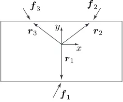
We consider a rigid object and point contacts, which means that only interaction forces, but no interaction torques may be applied to the object. However, the interaction forces may induce torques resulting on the object. For clarification Fig. 1 shows an object with an object-fixed coordinate system C, vectorsri pointing from the origin of the coordinate system
to the respective contact points and interaction forces fi.
The effect of an IFion the object can be twofold and thus,
x
f3
y
r1
z
r2
f1
r3
f2
[image:2.612.99.252.194.291.2]C
Fig. 1: Object interaction with three interaction points.
can be decomposed as follows:
fi =fc,i+fm,i. (1)
If wrenches resulting from the IFs exist, which compensate each other, the object is squeezed, stretched or distorted and an internal wrench describing the mechanical stress inside the object, also called internal forces [17], evolves. We call components of the IFs with this property compensating forces (CFs) and refer to them with fc,i throughout this paper. If wrenches resulting from an IF are not compensated, they accelerate/decelerate the object and an external wrench describing the motion of the object, also called external forces [17], evolves. We call components of the IFs with this property manipulating forces (MFs) and refer to them withfm,i.
The MFs generate a resulting wrenchwracting on the object
with
wr=
fr
τr
=
N
X
i=1
fi
ri×fi
| {z }
wi =
N
X
i=1
wi=W f
=
N
X
i=1
fm,i ri×fm,i
| {z }
wm,i =
N
X
i=1
wm,i=W fm
(2)
wherefris the accelerating force,τrthe accelerating torque
and
W =
I I · · · I
R1 R2 · · · RN
,
f = [fT1,· · ·fTN]T and fm= [fTm,1,· · · ,fTm,N]T,
wi=
fi ri×fi
and wm,i=
fm,i
ri×fm,i
,
wherebyIis the identity matrix andRithe skew symmetric
matrix operator ofri performing the cross product.
[image:2.612.71.302.524.607.2]f1 f2
Fig. 2: Two finger grasp example without gravity. (cp. [12])
CFs, on the other hand, generate internal wrencheswc,iand
following their definition they sum up to zero. It follows
N
X
i=1
fc,i
ri×fc,i
=
N
X
i=1
wc,i=W fc=0 (3)
with
wc,i=
fc,i
ri×fc,i
and fc= [fTc,1,· · ·fTc,N]T.
Using (1), (2) and (3), an under-determined system of equations results.
B. Related Work
In literature, different solutions to this under-determined system have been proposed as detailed in the introduction. In the following paragraphs, we will have a more detailed look at two representative solutions, the Virtual Linkage Model of Williams and Khatib [13] and the more intuitively derived approach of Yoshikawa and Nagai [18].
For a better comprehension of the Virtual Linkage Model the example shown in Fig. 2 will be used with
fm,1=f1, fc,1=0, and fm,2=0, fc,2=0. The general solution of the Virtual Linkage Model for the resulting MFs is
fm=WT(W WT)−1W f (4) which reduces to
fm,i =
1
Nfr+Ri
N
X
j=1
R2j
−1
τr if N
X
i=1
ri =0. (5)
It can be shown that the solution to (4) is invariant to shifts of the object-fixed coordinate system and thus, after shifting the reference frame to Piri = 0, (5) can be
considered a simplified solution of (4). From (5) it can be seen that the resulting forcefr on the object is distributed
equally on all MFs. For the example in Fig. 2 this means
fm,2=f1/26=0. Hence, even if an IF has no influence on the acceleration of the object, it is assigned an MF larger than zero. We call these forces virtual forces because they are physically implausible and therefore non-existent. Please note, however, that in manipulation tasks the MFs and CFs are always synthesized to IFs and these again to resulting forces and torques that act on the object. On this macroscopic level, virtual forces disappear and the law of energy conservation holds rendering object manipulation possible. Only when looking at the individual forces and their components virtual forces can be observed, which is problematic for IF analysis as these forces are the ones of main interest.
method is based on three intuitive assumptions: First, CFs should always be inside the friction cone. Second, an MF should have no part pointing into the inverse direction of the corresponding CF. Third, an MF has no part resulting in compression or tension of the object, neglecting torsion. From these assumptions, follow two steps for IF decompo-sition.
In the first step, possible grasp modes α = [α1,· · · , αm]
with αi ∈ {−1; 1} have to be chosen. A grasp mode
describes if CFs between two interaction points squeeze or stretch the object and depend on the surface normals and the friction coefficients at the interaction points. A grasp mode can be calculated for the three finger grasp by using the algorithm described in [12]. The CFs are described in a subspacehc using these grasp modes. In this subspace, a
solution is only feasible if all values are positive. Otherwise, paradoxically the grasp mode would define compression, while the subspace value would result in tension.
In the second step, given a grasp mode, different solutions to the MFs, again described in an own subspace hm, are
tested for feasibility, i.e. no MF results into tension or compression of the object neglecting torsion and no MF points into the inverse direction of its corresponding CF. The different solutions result from any perturbation of a selection vectork= [k1,· · ·, kl]withki∈ {0; 1}that selects possible
directions for the MFs.
From the above considerations, the following system of equations results:
wr=W f =W Bh ⇒ h=B−1f
withB=Bc(α,r1,· · ·,rn) Bm(k,α,r1,· · ·,rn),
h=hTc hTm
T
.
After calculating all solutions for the MFs from the perturba-tions ofk, the feasible solution, if one exists, has to be found by testing if the subspace values fulfill the assumptions. Using the resulting h, the CFs and MFs can be calculated by
fc=Bchc, fm=Bmhm.
This approach has multiple drawbacks. For example, it is possible that multiple grasp modes (see [12] for examples) and eventually multiple solutions exist or that no grasp mode exists. There may be also no selection vector, preventing a feasible solution and, thus, decomposition. This is due to the constraint requiring that an MF is composed of forces which do not lead to tension or compression for selected parts of the corresponding CF (compare Condition 3 for MFs in [12]), which also reduces the solution space to the empty set for most grasp configurations with four fingers. Furthermore, only algorithms are given to decompose two, three and four finger grasps, because complexity increases drastically when adding additional interaction points. Thus, it remains unclear if a solution for more than four fingers exists.
C. Proposed IF Decomposition
So far, the mathematical decomposition into MFs and CFs is based on the definitions given in Section II-A. We will
fi
2 |fi|
[image:3.612.381.490.48.156.2]2
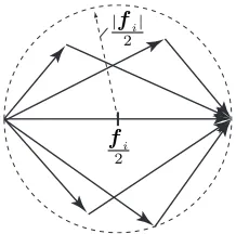
Fig. 3: The visualized solution space given by (6). Every vector combination consists offm,i andfc,i.
extend these definitions to allow only physically plausible individual interaction forces by introducing the following bounding constraint.
Bounding constraint: This constraint is inherently included
in the verbal definition of the MFs, but has not been moti-vated in literature yet to the best knowledge of the authors. Because an MF is the part of an IF, which accelerates the object, it also does physical work resulting in a differential change in energy of the object. Thus, by the law of energy conservation, the differential change in energy resulting from the MF cannot be larger than the one resulting from its corresponding IF. This is stated in Lemma 1 (see appendix for proof).
Lemma 1. Considering that an MF is the part of its IF, which performs physical work and taking (1) into account it follows
fTm,ifm,i+fTc,ifc,i≤fTi fi. (6) Remark: The inequality constraint (6) bounds the solution
space for the CFs and the MFs to a sphere around their respective IFs with radius |fi|/2as illustrated in Fig. 3 for two dimensions. Any violation of this inequality violates the law of energy conservation.
Given the bounding constraint, the solution space is reduced to physically plausible forces, but still an infinite number of solutions exist. A first intuitive approach to solve this problem would be to define that MFs contribute only to the resulting wrench on the object without any compensating parts, which we define as full decomposition. This constraint cannot be fulfilled for most manipulation situations and, thus, full decomposition would lead often to the empty set. This finding is formulated in Lemma 2 (see appendix for proof).
Lemma 2. Full decomposition of IFs into CFs leading to wrenches compensating each other and MFs contributing to the resulting wrench only, i.e. without compensating parts, is in general not possible.
Remark: The VL model achieves a weakened proposition.
It calculates only MFs which are not in the nullspace ofW.
the internal forces for a two finger grasp based on
fc,1/2=±min (|fT1e12|,| −fT2e12|)e12 with (7)
e12=
r2−r1
||r2−r1||
, (8)
where e12 represents the unit vector from one interaction point to the other. In (7) the interaction forces are projected on the line connecting the interaction points, which is also done in the VL model, and the smaller projected force is chosen as compensating component. This is due to the fact that both CFs have to compensate each other, which means that their norms have to be equal and thus, only the smaller norm can be fully compensated. In other words, the CFs are maximized which is the first property we abstract from this approach. Extending this idea to multiple fingers, we thus propose to design a cost function that maximizes the CFs. However, the solution space of the CFs has to be bounded so that they do not increase to infinity. In the approach by Yoshikawa and Nagai, this is achieved by the proposition that an MF should have no part pointing into the inverse direction of the corresponding CF and vice versa, i.e. 0≤fTm,ifc,i. To the best knowledge of the authors this constraint has not been physically motivated in literature yet. Using standard mathematical operations one can see that our newly intro-duced bounding constraint (6) is equal to the constraint of Yoshikawa and Nagai. For the first time we motivate this constraint based on an energy conservation argumentation for the individual interaction forces. This constraint is finally used to restrict the previously introduced optimization. A last property is given by the fact that CFs can only be applied along the line connecting the two interaction points, which is the only solution to (3) for the two finger grasp [19]. Hence, using (3) additionally to the bounding constraint allows us to expand the approach of Yoshikawa and Nagai to any number of fingers by formulating an optimization problem.
IF Decomposition Theorem (IFDT). For a precision grasp, the IF decomposition problem is given by the following optimization problem:
arg max
fc
J =|fc|
2
(9)
s.t. W fc=0, (10)
fTc,ifc,i≤fTifc,i ∀i. (11)
This optimization problem is also applicable to pulling forces. The formulated problem, however, is concave, be-cause it is equivalent to minimizingJ∗=− |f
c|
2
, meaning that the optimization could result in local minima [20]. Thus, online computation brings some difficulties. Please note that inequality (11) is equal to (6) (for details see proof of Lemma 1).
Remark: It can be shown that the solution for the two-finger
grasp equals the solution proposed by Yoshikawa and Nagai as shown in Lemma 3 and as proven in the appendix.
III. NUMERICALEXAMPLES
For illustration and comparison of the new decomposition approach with state-of-the-art approaches, namely the
ap-f1
r2
r1
f2
r3
f3
[image:4.612.372.499.48.153.2]x y
Fig. 4: A three finger grasp.
proach of Yoshikawa and Nagai [12] and the Virtual Linkage Model [13], the example of Fig. 4 is adopted with
f1=1 2T, r1=0 −2
T
,
f2=
−ε −1T, r2=
√
3 1T,
f3=
ε −1T, r3=
−√3 1T, and some ε ∈ R. Values in z-direction are assumed to be zero and it should be noted that r1+r2+r3 =0 so that (5) can be used directly. The decomposition based on the newly proposed IFDT was performed using the optimization toolbox of MATLAB adopting an interior-point algorithm, which is suitable for quadratic optimization problems with nonlinear equality and inequality constraints.
Assumingε= 0,f2andf3are compensated byf1and the only force influencing the objects motion is the x component off1. The MFs and CFs of the Virtual Linkage Model (vl) can be determined using (5) and (1) and are given by:
vlf
m,1≈
0.67 0T, vlfc,1≈0.33 2T,
vl
fm,2≈
0.17 0.29T, vlfc,2≈
−0.17 −1.29T,
vlf
m,3≈
0.17 −0.29T, vlf
c,3≈
−0.17 −0.71T. From this follows that
vlfT
m,2vlfm,2+vlfTc,2vlfc,2>fT2f2,
which is contradicting (6) and, thus, for vlfm,2 virtual forces are calculated. Also, vlfm,3 would contain virtual forces if the influence of f1 on the object’s motion gets larger (compare (5)). Summarizing, for the Virtual Linkage Model, we can conclude that an object accelerated mostly by a specific IF, with accelerating forces (MFs) much larger than the stabilizing forces (CFs), contains primarily virtual decomposed MFs.
Using the approach of Yoshikawa and Nagai the grasp modes shown in Fig. 5 result. However, for ε ∈ [0.356; 0.577]
there exists no solution because the constraint prohibiting the MFs to lead to tension or compression along a joining line cannot be fulfilled. Thus, there may always be grasp constellations preventing this decomposition. In contrast to these approaches, the IFDT leads to the following MFs and CFs, which are respecting the bounding constraint:
IF DTf
m,1=
1 0T, IF DTfc,1=0 2T,
IF DT
fm,2=
0 0T, IF DTfc,2=
0 −1T,
IF DTf
m,3=
0 0T, IF DTf
c,3=
x y
α=− + +
α=− + +
[image:5.612.128.278.52.176.2]α=+ + +
Fig. 5: Possible grasp modes for the example shown in Fig. 4 using the friction constantµ= 0.9.α= [−+ +]means that the CF between the interaction pointsr2andr3is stretching. α= [+ + +]means that all CFs are squeezing.
IV. EXPERIMENTALRESULTS
We further performed a series of experiments to better illustrate the capabilities of the new approach and to compare results with state-of-the-art approaches.
A. Experimental Setup and Procedure
A cylindrical object with diameter 5 cm was printed using rapid prototyping and fixed to the end-effector of a haptic interface that was operated in admittance control mode and used to simulate an object with an inertia of 5 or 10 kg restricted to movements in a horizontal plane. The object was instrumented with either 3 or 4 Touchence force sensors of type TSSI OD10 FPC19 on the circumference of the object. Each force sensor was covered with a small hemispherical pad to reduce the contact between finger and force sensors to a point, see Fig. 6. A virtual environment was developed showing a horizontal circle and the subjects were asked to move on this circle in clockwise direction. Two experiments were considered to illustrate the applicability of the new force decomposition approach to the analysis of: 1) a three finger precision grasp and 2) human-human collaboration involving two interaction points for each human. Compensat-ing and manipulatCompensat-ing forces were analyzed for both scenarios using different force decomposition approaches.
Touchence force sensors
Hemispherical pad
Force sensor of haptic interface used for admittance control
Amplifier boards of Touchence sensor
[image:5.612.316.555.278.358.2]Virtual environment
Fig. 6: Experimental setup showing the instrumented object mounted at the end-effector of a haptic interface and virtual environment (lower right corner)
1) Precision Grasp: Three force sensors were placed at
an angular distance of 120 degrees on the circumference of the object, see Fig. 7, left. The subject was asked to grasp the object using a three finger circular precision grasp and to move the object clockwise along the circle shown in the virtual environment. A fast trial with10kg and a slow trial with5kg inertia were recorded.
2) Human-Human Collaboration: Four force sensors
were placed at an angular distance of 120-60-120-60 degrees on the circumference of the object. Two subjects were asked to collaborate on the task of moving the object along the circle shown in the virtual environment. Each subject used a two finger precision grasp touching two adjacent force sensors, see Fig. 7, right. To avoid collisions with their hands, one subject grasped the object from the side, while the other subject grasped the object from above. Subjects were initially assigned the role of a leader and follower and instructed to alternately switch their role after every completed circle.
Fig. 7: Subjects holding the object in the precision grasp (left) and human-human collaboration experiment (right)
B. Results
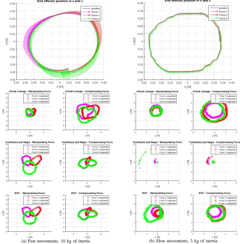
1) Precision Grasp: Fig. 8 illustrates the obtained force
decomposition results for the Virtual Linkage Model, the method proposed by Yoshikawa and Nagai and the newly proposed IFDT method. The graphs on top illustrate the direction and amplitude of the IFs measured at the individual contact points when moving in clockwise direction along the virtual circle. The length of the vectors corresponds hereby to the amplitude of the IFs. Below, manipulating and compensating forces are shown separately for each method. In Fig. 8a a fast movement is shown where forces at the individual contact points reach their maximum when the movement direction is vertical to the force sensor surface. While this effect can be clearly seen in the plots for the MFs of the methods of Yoshikawa and Nagai and the proposed IFDT method, the Virtual Linkage Model averages this effect over all manipulating forces and thus, leads to virtual forces. Fig. 8b shows the same task, but now performed much slower. As can be seen, the results of the three methods are now much more similar. For the Yoshikawa method, however, no solution could be found for various points on the circle.
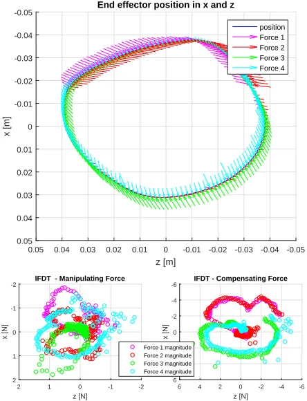
2) Human-Human Collaboration: Fig. 9 illustrates the
[image:5.612.65.283.549.693.2]z [m] -0.05 -0.04 -0.03 -0.02 -0.01 0 0.01 0.02 0.03 0.04 0.05 x [m] -0.05 -0.04 -0.03 -0.02 -0.01 0 0.01 0.02 0.03 0.04 0.05
End effector position in x and z
position Force 1 Force 2 Force 3 z [N] -5 0 5 x [N] -8 -6 -4 -2 0 2 4 6 8
Virtual Linkage - Manipulating Force
Force 1 magnitude Force 2 magnitude Force 3 magnitude
z [N] -5 0 5 x [N] -8 -6 -4 -2 0 2 4 6 8
Virtual Linkage - Compensating Force
Force 1 magnitude Force 2 magnitude Force 3 magnitude
z [N] -5 0 5 x [N] -8 -6 -4 -2 0 2 4 6 8
Yoshikawa and Nagai - Manipulating Force Force 1 magnitude Force 2 magnitude Force 3 magnitude
z [N] -5 0 5 x [N] -8 -6 -4 -2 0 2 4 6 8
Yoshikawa and Nagai - Compensating Force Force 1 magnitude Force 2 magnitude Force 3 magnitude
z [N] -5 0 5 x [N] -8 -6 -4 -2 0 2 4 6 8
IFDT - Manipulating Force Force 1 magnitude Force 2 magnitude Force 3 magnitude
z [N] -5 0 5 x [N] -8 -6 -4 -2 0 2 4 6 8
IFDT - Compensating Force Force 1 magnitude Force 2 magnitude Force 3 magnitude
(a) Fast movements,10kg of inertia
z [m] -0.05 -0.04 -0.03 -0.02 -0.01 0 0.01 0.02 0.03 0.04 0.05 x [m] -0.05 -0.04 -0.03 -0.02 -0.01 0 0.01 0.02 0.03 0.04 0.05
End effector position in x and z
position Force 1 Force 2 Force 3 z [N] -2 -1 0 1 2 x [N] -2 -1 0 1 2
Virtual Linkage - Manipulating Force Force 1 magnitude Force 2 magnitude Force 3 magnitude
z [N] -2 -1 0 1 2 x [N] -2 -1 0 1 2
Virtual Linkage - Compensating Force Force 1 magnitude Force 2 magnitude Force 3 magnitude
z [N] -2 -1 0 1 2 x [N] -2 -1 0 1 2
Yoshikawa and Nagai - Manipulating Force
Force 1 magnitude Force 2 magnitude Force 3 magnitude
z [N] -2 -1 0 1 2 x [N] -2 -1 0 1 2
Yoshikawa and Nagai - Compensating Force
Force 1 magnitude Force 2 magnitude Force 3 magnitude
z [N] -2 -1 0 1 2 x [N] -2 -1 0 1 2
IFDT - Manipulating Force
Force 1 magnitude Force 2 magnitude Force 3 magnitude
z [N] -2 -1 0 1 2 x [N] -2 -1 0 1 2
IFDT - Compensating Force
Force 1 magnitude Force 2 magnitude Force 3 magnitude
[image:6.612.70.544.55.537.2](b) Slow movements,5kg of inertia
Fig. 8: Manipulating and compensating forces for the precision grasp experiment
virtual linkage is at a singularity and consequently the grasp description matrix becomes deficient, see [13] for more information. In contrast, the IFDT scheme provides a physical plausible decomposition during offline computation. This clearly demonstrates the superiority of the proposed IFDT scheme in this case, where it comes to more than three interaction points.
In the top figure, the switching roles between the users can be observed. While in the upper half of the circle, user one (represented by interaction forces one and two) dominated the task, in the lower half of the circle, user two (represented by interaction forces three and four) dominated. Looking more carefully at the two forces recorded for each individual, one can see that the manipulating forces one and
three dominated the task at specific angles on the circle. Analyzing these moments more carefully, it can be observed that the manipulating forces reach their maximum at points when the particular interaction force is applied tangential to the circle, allowing to use the whole force for accelerating the object. Corresponding results with a dominating finger two and four would be obtained for the reverse order of roles or the inverse direction of movement.
V. CONCLUSION
z [m]
-0.05 -0.04 -0.03 -0.02 -0.01 0 0.01 0.02 0.03 0.04 0.05
x [m]
-0.05
-0.04
-0.03
-0.02
-0.01
0
0.01
0.02
0.03
0.04
0.05
End effector position in x and z
position Force 1 Force 2 Force 3 Force 4
z [N]
-2 -1 0 1 2
x [N]
-2
-1
0
1
2
IFDT - Manipulating Force
z [N]
-6 -4 -2 0 2 4 6
x [N]
-6
-4
-2
0
2
4
6
IFDT - Compensating Force
[image:7.612.66.288.53.343.2]Force 1 magnitude Force 2 magnitude Force 3 magnitude Force 4 magnitude
Fig. 9: Manipulating and compensating forces for the human-human collaboration experiment
and extended to more than two interaction points resulting in an optimization problem, which maximizes CFs. This maximization is only possible due to a new introduced bounding constraint, which bounds the solution space of the MFs and the CFs. The constraint is motivated by considering that a force component cannot do more physical work than the original interaction force.
Existing decomposition approaches were compared to the newly proposed IF decomposition. The Virtual Linkage Model was found to lead to implausible MFs when taking into account the law of conservation of energy for each interaction force separately and suffers from singularities at certain configurations. In contrast, the drawbacks of the method of Yoshikawa and Nagai were found to be that solu-tions are currently restricted to two, three and four interaction points, and that depending on the specific configuration, no decomposition can be obtained, specifically for grasps with more than three interaction points.
Since the optimization problem introduced in our IFDT method contains a quadratic constraint which complicates an analytical solution and focuses on forces only, our future work will target a numerical solution for online decomposi-tion of IFs as well as its extension to include torques.
APPENDIX
Lemma 1. Considering that an MF is the part of its IF which performs physical work and taking (1) into account, it follows
fTm,ifm,i+fTc,ifc,i≤fTifi. (12)
Proof. Because an MF is the part of its IF contributing to
the accelerating wrench acting on the object, two properties can be formulated: First, the projection of the IF on its corresponding MF
fi,proj=
fTi
fm,i |fm,i|
f
m,i |fm,i|
(13)
can be used to describe an upper bound for the physical work performed by the MF. Second, if the work performed by the IF is positive/negative, also the work done by the corresponding MF must be positive/negative. From these statements, the following two inequalities can be formulated which must hold for every infinitesimal line segment dr= rdswith|r|= 1
0(≤>)fTm,irds
(>)
≤ fTi,projrds (14)
or rotary segment dφ=qdϕwith|q|= 1
0
(>)
≤ ri×fm,i
T
qdϕ (>)
≤ ri×fi,proj
T
qdϕ. (15)
Substituting (13) into (14) and (15) yields
0
(>)
≤ fTm,irds
(>)
≤ cifTm,irds,
0(≤>)ri×fm,i
T
qdϕ(≤>)ci
ri×fm,i
T
qdϕ
with
ci =fTi
fm,i |fm,i|2
.
Comparing the coefficients it follows
0≤1≤ci. (16)
Substitutingci into (16) leads to
0≤fTm,ifm,i=|fm,i|2≤fTifm,i. (17)
Since fTi fm,i ≥ 0 the angle α between fi and fm,i is
within[−π/2;π/2]. When substituting (1) into (17) follows
0≤fTc,ifc,i=|fc,i|2≤fTifc,i. (18)
Using standard mathematical operations, we can get (12) from either (17) or (18) when assuming that (1) holds.
Lemma 2. Full decomposition of IFs into CFs leading to wrenches compensating each other and MFs contributing to the resulting wrench only, i.e. without compensating parts, is in general not possible.
Proof. Assume that the wrenchwm,i, exerted by an MF on
the object, is not pointing into the direction of wr. Then,
the deviation between wm,i and wr must be compensated
by another wrench wm,j where j 6= i, contradicting full
decomposition. Consequently, all wm,i must point into the
direction of wr. This can be formulated mathematically,
when describing the MFs with two parts: one part pointing into the direction offr and a second part, denoted asfx,i,
leading to a torque aligned with the direction ofτr.
fm,i =d1fr+fx,i d1∈R+0, (19)
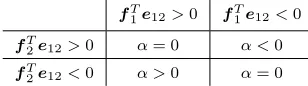
TABLE I: Possible sets ofαfor given projections of the IFs on the line connecting the interaction points.
fT1e12>0 fT1e12<0
fT
2e12>0 α= 0 α <0 fT
2e12<0 α >0 α= 0
In (20), the torque on the left side is orthogonal tori, while
the torque on the right side is aligned with the direction of
τr. Thus, a solution to (20) exists only if τr is orthogonal
to ri. It is easy to find an example which contradicts this
constraint and, thus, it can be concluded that in general, the MFs cannot have only parts contributing to the resulting wrench, but will also contain compensating wrenches.
Lemma 3. The solution to the two-finger grasp obtained with the newly proposed IFDT equals the intuitive solution
(7) derived by Yoshikawa and Nagai [18].
Proof. For the two-finger grasp constraint (10) can be written
as follows
I I
R1 R2
fc,1
fc,2
=0. (21)
From the first row follows that the two CFs have equal norms and point in opposite directionsfc,2=−fc,1. Inserting this result into the second row of (21) and rewriting the cross product in its original form gives
(r1−r2)×fc,1=0
with the trivial solution fc,1 =fc,2 =0 or fc,1 andfc,2 parallel tor1−r2. The non-trivial solution means that both CFs lie on the line connecting the two interaction points, which can be parametrized usinge12 from (8):
fc,1=αe12, fc,2=−αe12 α∈R. (22) Thus, the valueαremains to be determined. Using (22) the optimization problem (9)-(11) can be reformulated to
arg max
α J = 2α
2 (23)
s.t. α2≤αfT1e12, (24)
α2≤ −αfT2e12. (25)
Assume that fT1e12 > 0 and fT2e12 < 0 and note that the left sides of (24) and (25) are always positive or zero. Then, if α ∈ R−0, (24) and (25) allow the solutionα = 0 only. On the other hand, if α∈ R+0, the cost function can take positive values. Similar considerations can be made for all other combinations of signs of fT1e12 and fT2e12, summarized in Table I. Hence, dependent on the IFs and the line connecting the interaction points, one out of four possible solutions exists for maximization of (23) under the constraints (24) and (25). Two of them require α= 0. The other two can be determined by reformulating (24) and (25) as follows
if α >0⇒
(
α≤fT1e12=k1 α≤ −fT2e12=k2
(26)
if α <0⇒
(
α≥fT1e12=−k1 α≥ −fT2e12=−k2
(27)
withk1, k2∈R+0. IffT1e12>0andfT2e12<0,αis posi-tive and must be maximized under constraint (26). Thus,α equals eitherk1ork2. Second, iffT1e12<0andfT2e12>0, αis negative and must be minimized under constraint (27). Thus,αequals either−k1or−k2. Combining these results, we can state that
α=±min(|fT1e12|,| −fT2e12|). (28) Thus, by inserting (28) into (22) we get (7).
REFERENCES
[1] D. Prattichizzo, M. Malvezzi, M. Aggravi, and T. Wimbock, “Object motion-decoupled internal force control for a compliant multifingered hand,” in IEEE International Conference on Robotics and Automation, May 2012, pp. 1508–1513.
[2] M. Buss, H. Hashimoto, and J. Moore, “Dextrous hand grasping force optimization,” IEEE Transactions on Robotics and Automation, vol. 12, no. 3, pp. 406–418, 1996.
[3] K. B. Reed and M. A. Peshkin, “Physical collaboration of human-human and human-human-robot teams,” IEEE Transactions on Haptics, vol. 1, pp. 108–120, 2008.
[4] R. Groten, D. Feth, H. Goshy, A. Peer, D. A. Kenny, and M. Buss, “Experimental Analysis of Dominance in Haptic Collaboration,” in Proc. of the 18th International Symposium on Robot and Human Interactive Communication, 2009.
[5] N. Stefanov, A. Peer, and M. Buss, “Role Determination in Human-Human Interaction,” in Worldhaptics, 2009.
[6] T. Yoshikawa and X. Zheng, “Coordinated dynamic hybrid posi-tion/force control for multiple robot manipulators handling one con-strained object,” in IEEE International Conference on Robotics and Automation, vol. 2, May 1990, pp. 1178–1183.
[7] D. Sun and J. Mills, “Manipulating rigid payloads with multiple robots using compliant grippers,” IEEE/ASME Transactions on Mechatronics, vol. 7, no. 1, pp. 23–34, Mar 2002.
[8] M. A. Smith and J. F. Soechting, “Modulation of grasping forces during object transport.” Journal of Neurophysiology, vol. 93, no. 1, pp. 137–145, 2005.
[9] G. Slota, M. Latash, and V. Zatsiorsky, “Grip forces during object manipulation: experiment, mathematical model, and validation,” Ex-perimental Brain Research, vol. 213, pp. 125–139, 2011.
[10] A. M. Schmidts, D. Lee, and A. Peer, “Imitation learning of human grasping skills from motion and force data,” in IEEE/RSJ International Conference on Intelligent Robots and Systems, 2011.
[11] M. Aicardi, G. Casalino, and G. Cannata, “Contact force canonical decomposition and the role of internal forces in robust grasp planning problems,” International Journal on Robotic Research, vol. 15, no. 4, pp. 351–364, Aug 1996.
[12] T. Yoshikawa and K. Nagai, “Manipulating and grasping forces in manipulation by multifingered robot hands,” IEEE Transactions on Robotics and Automation, vol. 7, no. 1, pp. 67 –77, Feb 1991. [13] D. Williams and O. Khatib, “The virtual linkage: a model for internal
forces in multi-grasp manipulation,” in IEEE International Conference on Robotics and Automation, vol. 1, May 1993, pp. 1025 –1030. [14] A. Bicchi, “Force distribution in multiple whole-limb manipulation,”
in IEEE International Conference on Robotics and Automation, vol. 2, 1993, pp. 196–201.
[15] Y. Zhang and W. Gruver, “Definition and force distribution of power grasps,” in IEEE International Conference on Robotics and Automa-tion, vol. 2, 1995, pp. 1373–1378.
[16] Y. Zhang, W. Gruver, J. Li, and Q. Zhang, “Classification of grasps by robot hands,” IEEE Transactions on Systems, Man, and Cybernetics, vol. 31, no. 3, pp. 436–444, 2001.
[17] B. Siciliano and O. Khatib, Eds., Springer Handbook of Robotics. Springer, 2008.
[18] T. Yoshikawa, “Virtual truss model for characterization of internal forces for multiple finger grasps,” IEEE Transactions on Robotics and Automation, vol. 15, no. 5, pp. 941 –947, Oct 1999.
[19] V. Kumar and K. Waldron, “Force distribution in closed kinematic chains,” in IEEE International Conference on Robotics and Automa-tion, vol. 1, 1988, pp. 114–119.
![Fig. 2: Two finger grasp example without gravity. (cp. [12])](https://thumb-us.123doks.com/thumbv2/123dok_us/613839.561804/2.612.71.302.524.607/fig-nger-grasp-example-gravity-cp.webp)