Stainless Steel Multicontact Electrodes
Linda C. Meiners, Chris J. G. Bakker, Peter C. van Rijen, Cees W. M. van Veelen, Alexander C. van Huffelen, Andre van Dieren, Gerard H. Jansen, and Willem P. T. M. Mali
Summary: A three-dimensional fast spin-echo MR technique is proposed for locating contact points on implanted intracerebral multicontact electrode bundles. Coronal or sagittal reformatting shows the entire trajectory of the electrode bundles. The contact points are clearly visible owing to the absence of coating material associated with a slightly larger susceptibility artifact. Poten-tially, this technique may preclude postimplantation thin-section CT, with its associated high radiation dose.
Index terms: Brain, magnetic resonance; Seizures
In preoperative examinations to locate sei-zure focus in patients with therapy-resistant ep-ilepsy, it is sometimes necessary to implant subdural and intracerebral electrodes. Once the electrodes are placed, the position of the con-tact points must be verified. A variation on the method of combined implantation of intracere-bral and subdural electrodes proposed by van Veelen et al (1) was used in the present study. This method consists of preimplantation three-dimensional magnetic resonance (MR)-guided stereotactic surgery with a Leksell frame and postimplantation 3-D computed tomographic (CT) examination as described by Gerritsen et al (2). Postimplantation CT is, however, associ-ated with a high radiation dose, and the elec-trode contact points are not visible on CT scans. Large susceptibility artifacts associated with the commonly used 3-D gradient-echo MR volume imaging also limit visibility of the contact points. In an attempt to overcome these limita-tions, a postimplantation 3-D fast spin-echo MR sequence is proposed.
Materials and Methods Patients
The MR images of three patients who were referred for surgical treatment of drug-resistant epilepsy were used in this study. Extensive preimplantation examinations in-cluded ictal and interictal surface electroencephalographic (EEG) recording with video monitoring, MR imaging, and positron emission tomography. Because these studies did not center on one abnormal area in the brain, evaluation with depth-electrode EEG registration was undertaken.
Materials
The depth electrodes consisted of six insulated record-ing wires glued around one supportrecord-ing stainless steal wire (Brain Electronics, De Bilt, the Netherlands). The contact points on the intertwined recording wires were created by removing the polymer biocompatible coating over a short distance at different levels for each wire (Fig 1A–D). The four distal contact points were 2.5 mm long separated by 2.5-mm intervals. The remaining two proximal contacts were 5 mm in length separated by 7.5-mm intervals. The total diameter of a depth-electrode bundle was 0.4 mm. The depth electrodes and the method of implantation have been described in detail (1).
Before the patients were studied, the electrodes were tested for ferromagnetism. No deflection was found, which was in agreement with the findings described by Brooks et al (3). Our electrodes consisted of an alloy containing 14% chromium and 12% nickel. As this alloy is similar to that described in the study by Zhang et al (4), the heat pro-duced during MR imaging was considered negligible.
Study Design
For each patient a preimplantation 3-D gradient-echo MR image was obtained on a 0.5-T system with an MR-compatible Leksell stereotactic frame (Electra, Stock-holm, Sweden) in situ. Implantation of the depth
elec-Received November 16, 1995; accepted after revision February 15, 1996.
From the Departments of Radiology (L.C.M., C.J.G.B., W.P.T.M.M.), Neurosurgery (P.C.V.R., C.W.M.V.V.), Clinical Neurophysiology (A.C.V.H.), Surgery (A.V.D.), and Pathology (G.H.J.), University Hospital Utrecht (the Netherlands).
Address reprint requests to Linda C. Meiners, MD, Department of Radiology, University Hospital Utrecht, Heidelberglaan 100, 3584 CX Utrecht, the Netherlands.
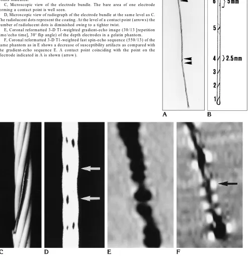
Fig 1. A, Photograph of intracerebral electrode with two contact point lengths indicated byarrowheads(enlargement32, similar to that ofEandF).
B, Schematic representation of electrode bundle with the six separate contact points indicated.
C, Microscopic view of the electrode bundle. The bare area of one electrode forming a contact point is well seen.
D, Microscopic view of radiograph of the electrode bundle at the same level asC. The radiolucent dots represent the coating. At the level of a contact point (arrows) the number of radiolucent dots is diminished owing to a tighter twist.
E, Coronal reformatted 3-D T1-weighted gradient-echo image (30/13 [repetition time/echo time], 308flip angle) of the depth electrodes in a gelatin phantom.
[image:2.612.48.541.124.632.2]trodes was performed via MR-guided stereotactic surgery. After the electrodes were placed, a 3-D reformatted CT scan was obtained with the stereotactic frame in place. This was done to exclude the possibility that an intracranial hematoma had developed and to determine the location of the implanted electrodes. When the preimplantation MR image was matched with the postimplantation CT scan, it was possible to depict the electrode bundles; however, the separate contact points were not visible.
An MR examination was performed 2 days after the implantation procedure and removal of the frame to deter-mine the final position of the electrodes before EEG reg-istration. A 3-D T1-weighted fast spin-echo sequence was used in all three cases, with an orientation similar to that of the preoperative MR study. The parameters used for the three patients were slightly modified in order to obtain an optimal scan sequence. The three sequences used are shown in the Table.
To demonstrate the advantage of fast spin-echo over gradient-echo for the postoperative MR examination, the depth electrodes were scanned in a phantom consisting of gelatin using the scanning sequences described above (Fig 1E and F).
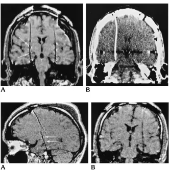
Fig 2. A, Coronal reformatted T1-weighted fast spin-echo MR image (550/ 13) shows the trajectory of the depth elec-trodes. The six contact points are well demarcated owing to a local increase in susceptibility artifacts (arrows).
B, Coronal reformatted CT scan shows the same trajectory of the electrode as seen on the MR image (A).
Fig 3. A, Sagittal reformatted fast spin-echo MR image (550/13), section thickness of 1.2 mm with left-to-right phase-encoding gradient, shows the sepa-rate contact points (arrows).
B, Coronal reformatted fast spin-echo MR image (550/13) with 1.2-mm section thickness and left-to-right phase-encoding direction. The contact points are less visi-ble.
Three fast spin-echo sequences used in three patients with im-planted depth electrodes
Patient 1 Patient 2 Patient 3
Repetition time 550 550 550
Echo time 13 13 13
Field of view (FOV) 250 250 250
Rectangular FOV, % 80 80 80
Echo train length 5 5 5
Profile order* Centric Centric Centric
No. of excitations 1 1 1
Scan, % 90 90 90
Bandwidth/pixel 166 197 166
Section thickness, mm 1.5 1.2 1.5 Overlapping sections Yes No No
No. of sections 120 120 108
No. of volume chunks 10 10 6
Phase-encoding direction Left-right Left-right Anteropos-terior
Scan time, min 5.34 11.01 17.31
* First measurement is made at K0followed by profile acquisition
[image:3.612.45.285.113.297.2] [image:3.612.44.375.401.734.2]Results
The fast spin-echo images of the phantom study confirmed the reduction in metal artifacts accompanying the electrodes as compared with the gradient-echo sequence (Fig 1E and F).
The 3-D fast spin-echo acquisition allowed reformatting in multiple planes (Figs 2 and 3). Reformatting of the postimplantation axial im-ages in the coronal and sagittal planes showed the trajectory of the intracerebral depth elec-trodes (Figs 2A and 3A), which was compara-ble to that shown on the postoperative CT scan (Fig 2A and B). The contact points created a small area of increased susceptibility artifacts. The position of the contact points on the MR images corresponded to the area in which the polymer biocompatible coating was removed, as shown in the phantom study in Figure 1. With the use of an anteroposterior phase-encoding gradient direction, the electrode contact points were best seen and isolated on the coronal re-formatted images. A phase-encoding direction from left to right resulted in optimal depiction in the sagittal reformatted plane, with the suscep-tibility artifact projecting in the anteroposterior direction relating to the frequency-encoding gradient (Fig 3A). In the latter case, the individ-ual contact points could not be isolated on the coronal reformatted images (Fig 3B).
Discussion
The development of 3-D MR imaging and later of appropriate computer programs ad-justed to different stereotactic frames has made it possible to indicate accurately the desired intracerebral position of electrodes prior to sur-gery. Postimplantation CT with 1.5-mm sec-tions followed by 3-D reformatting provides a method to determine the position of intracere-bral and subdural stainless steel electrodes. Matching the preimplantation MR image with the postimplantation CT scan has proved to be a useful technique to depict the exact anatomic location of the electrodes. This position is sub-sequently equated with the depth EEG data to delineate the seizure onset zone as accurately as possible.
Because of the high radiation dose accompa-nying CT studies, it is preferable to examine the postimplantation patient solely with MR imag-ing. A two-dimensional spin-echo sequence may provide a method by which to view the
electrode bundle and its contact points with lim-ited susceptibility artifacts (5). However, if the intracerebral electrodes follow a curved trajec-tory, they may not be optimally captured in one section. Three-dimensional MR imaging with multiplanar reformatting provides an optimal way to show the electrode bundles throughout their course. Initially, 3-D MR images could only be obtained by using a gradient-echo sequence. However, when used with steel electrodes, this technique caused extensive susceptibility arti-facts, making it impossible to locate the contact points. To overcome this obstacle, Duckwiler et al (6) used intracerebral electrodes that con-sisted of 79% platinum and a 21% alloy of rho-dium and ruthenium. The disadvantage of using these electrodes is that they are more expensive than those made of stainless steel.
Three-dimensional fast spin-echo scans are inherently less susceptible to artifacts caused by metal implants. The T2* effect is reduced owing to the presence of refocusing 1808pulses following the 908 pulse. A T1-weighted se-quence is preferred for demonstration of the anatomy of the brain; therefore, a T1-weighted fast spin-echo sequence was developed.
The proposed postimplantation MR imaging procedure (see data for patient 3 in the Table) shows the trajectory of the intracerebral elec-trodes as well as CT does. In addition, the high spatial and contrast resolution of MR imaging results in optimal visibility of the electrodes in relation to anatomic structures. The short echo time in this study, the large bandwidth, and the use of an appropriate direction of the phase-encoding gradient enabled us to identify the contact points on these MR images. This has not been possible with CT. If coronal reconstruc-tions of axial 3-D secreconstruc-tions are made, the clear-est view of the contact points is obtained by using a phase-encoding gradient in the antero-posterior direction. The susceptibility artifacts associated with the direction of the frequency-encoding gradient will then be visible in the left-to-right direction. Sagittally reformatted im-ages show the electrode contact points best if a left-to-right phase-encoding gradient is used.
Although the contact points on the intracere-bral electrodes are well seen without deforma-tion of surrounding tissues, the subdural
elec-trode contact points remain difficult to
of the electrode bundle on the 2-D reformatted images with 3-D reformatting of the brain and the electrodes.
One important point that remains to be ad-dressed is the matter of the local increase in susceptibility artifacts at the contact points. The phantom study confirmed that the local areas of susceptibility artifacts coincided with the con-tact points. No paint or other materials were used at the site of the contact points. To study the possible susceptibility of the coating itself, a separate electrode with the coating removed was scanned over a longer distance. No differ-ence in susceptibility artifacts was noted be-tween coated and noncoated electrodes. To as-sess the configuration of the electrode bundle, a radiograph was made. A microscopic view showed the coating to be radiolucent and to appear as black dots. At the level of the contact points, the number of dots was reduced (Fig 1C), presumably because of a tighter twist of the electrode bundle, which resulted in a slight reduction of the diameter of the bundle (this was confirmed by a large-scale model made of elec-tricity wires). This region was then associated with a different susceptibility. The change in susceptibility resulted in a local increase in dephasing and a larger susceptibility artifact. This finding may well prove to be of relevance in looking at MR-compatible guidewires during in-vasive MR procedures.
The overall result of the described scanning procedure is a reformatted scan with high spa-tial and high contrast resolution that provides satisfactory demarcation of the contact points of electrodes without significant distortion of surrounding brain tissue. The sequence has been applied successfully in two additional pa-tients.
References
1. Van Veelen CWM, Debets RMC, Van Huffelen AC, et al. Combined use of subdural and intracerebral electrodes in preoperative eval-uation of epilepsy.Neurosurgery1990;26:93–101
2. Gerritsen FA, Van Veelen CWM, Mali WPTM, et al. Some require-ments for and experience with covira algorithms for registration and segmentation. In: Beolchi L, Kuhn MH, eds.Medical Imaging: Analysis of Multimodality 2D/3D Images.Amsterdam, the Neth-erlands: IOS Press; 1995;19:4 –28
3. Brooks ML, O’Connor MJ, Sperling MR, Mayer DP. Magnetic res-onance imaging in localization of EEG depth electrodes for seizure monitoring.Epilepsia1992;33:888 – 891
4. Zhang J, Wilson CL, Levesque MF, Behnke E, Lufkin RB. Tem-perature changes in nickel-chromium intracranial depth elec-trodes during MR scanning.AJNR Am J Neuroradiol 1993;14: 497–500
5. Spencer SS, So NK, Engel J Jr, Williamson PD, Levesque MF, Spencer DD. Depth electrodes. In: Engel J Jr, ed.Surgical Treat-ment of the Epilepsies.2nd ed. New York, NY: Raven Press; 1993: 359 –376
6. Duckwiler GR, Levesque M, Wilson CL, Behnke E, Babb TL, Lufkin R. Imaging of MR-compatible intracerebral depth electrodes.