Page | 1
Establishing a range of motion boundary for total hip
arthroplasty
Authors: G.A. Turley, S.M.Y. Ahmed, M.A. Williams & D.R. Griffin.
Abstract
Range of motion of the hip joint is a major contributor to dislocation post total hip replacement. Impingement is often treated as a surrogate for dislocation and occurs – prosthetically – when the neck of the femoral component contacts with the rim of the pelvic acetabular cup. This impingement is caused by movement of the leg during activities of daily living. This article analyses hip joint range of motion and its implication for impingement.
A systematic literature review was undertaken with the purpose of establishing a range of motion benchmark for total hip replacement. This paper proposes a method by which a three-dimensional range of motion boundary established from the literature can be presented. The nominal boundary is also validated experimentally using a number of configurations of a neutral hip joint coordinate frame.
1.
Introduction
Total Hip Arthroplasty (THA) is regarded as a successful technique which restores lost mobility to patients, suffering from osteoarthritis (OA), rheumatoid arthritis (RA) and acute trauma [1, 2]. THA procedures which permit the patient to walk, climb stairs and sit on a chair without pain or dislocation are often considered adequate [3]. However, humans can assume more than a thousand positions that are used in combination with movement to perform various Activities of Daily Living (ADL) [4]. Consequently, there are more demanding postures that a patient can assume, but these increase the demands placed on THA in terms of its resistance to dislocation [3].
Page | 2 Dislocation is one of the most common complications for a patient post THA, with an acknowledged failure rate of 1-5% for primary THA procedures for patients presenting with OA or RA [5-11]. A series of retrievals, from THA patients who had dislocated, found that 90% of dislocations had evidence of impingement [12]. Impingement related dislocations are associated with contact between the two prosthetic components, femur on pelvis contact or combination of prosthetic and bone contact [6]. Consequently, there is an interactive effect between the surgical technique, the prosthetic options available to surgeon and the prosthetic design which need to be understood [13-19].
Prosthetic impingement, occurs when a patient’s desired Range of Motion (ROM) causes the neck of the femoral component to contact with the rim of the acetabular cup. If motion continues, the hip joint centre of rotation moves from the femoral head centre to the rim of the acetabular cup. Further motion leads to subluxation of the femoral head until it ‘jumps out’ of the acetabular cup and dislocation occurs [5, 6, 15]. Therefore, improving the ROM to impingement is directly correlated to improved resistance to dislocation [14]. Determining a boundary for an impingement-free ROM would allow surgeons to plan the operative procedure to achieve optimum positioning [17].
Page | 3
2.
Establishing range of motion values
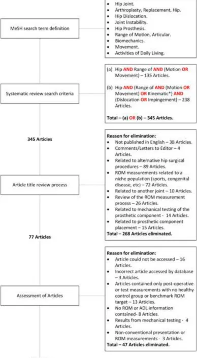
A systematic review of the literature was conducted to obtain information defining typical ADLs and experimental data with regard to pure joint motion and ADL joint motion angles. Fig. 1, provides a schematic of the systematic review process. The MEDLINE database was used for the systematic search of the literature, with articles from 1950 onwards being searched. A total of 30 relevant articles were yielded from the systematic search of the literature [3-6, 13, 17, 18, 19, 21-42]. Subsequently, the references and citations of these 30 articles were reviewed to produce a further 22 articles [16, 20, 43-62]. Therefore, a total of 52 articles were used to obtain hip joint kinematic data for pure joint motion and ADLs.
2.1
Establishing pure joint motion values
Articles relating to measurement or benchmark values for pure joint motion were identified from the systematic search of the literature. The purpose was to determine reference pure joint motion boundary conditions – flexion/extension in the sagittal plane, abduction/adduction in the coronal plane and internal/external rotation in the transverse plane – to ensure impingement free motion. The values for pure joint motion presented in these articles were categorised into three classes.
[Clinical] – Clinical measurements of hip joint motion using goniometer or photographic
techniques [20, 22, 23, 28, 37, 38, 48, 51, 61, 62].
[Reference] – Reference values of hip joint motion without indication of distribution, from
orthopaedic and physical therapy literature [39, 43-45, 47, 49, 50, 52, 53, 55].
[Simulation] – Pure joint motion benchmarks for use in computer simulations [13, 16-19, 32,
40-42, 60].
over-Page | 4 estimate the ROM requirement and are larger in all anatomical planes when compared with the other two categories [60].
To be able to derive a prosthetic ROM benchmark for all anatomical planes, it was required to infer a boundary within which patients would be impingement-free post-THA, during their ADL. It was
found that owing to the ability of subjects to compensate through inter-joint adaptation, many ADLs including those at the higher end of the demand scale could be done by THA patients within a tighter mean boundary than many of defined [Reference] values [20, 22]. Based on this finding and the elimination of the [Simulation] articles,the [Clinical] measures were compared further to the [Reference] figures.
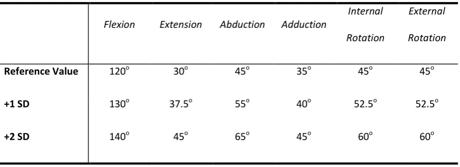
5-Page | 5 20o range of the [Reference] values in both the coronal and sagittal planes. In the transverse plane, one of the studies fell below the lower limit of the [Reference] range [38]. Therefore, based on this alignment between the [Clinical] and [Reference] values, the articles quoting the higher pure joint motion values within the [Reference] group were taken to be the recommended mean pure joint motion values for a healthy population. Distribution was estimated by pooling the standard deviation values from the two active ROM [Clinical] studies for each element of pure joint motion. Table 1, provides these benchmark figures.
2.2
Defining activities of daily living and establishing their values
A dislocation event occurs, in 90% of cases, when the ROM of a patient moves outside the boundary which the THA can accept [12]. The direction of dislocation has been traced to particular types of movement or posture [6, 35]. As well as these risk manoeuvres, there are other movements and postures that a person is likely to assume during the course of their daily activities. These range from high demand postures considered to be advanced activities [3, 4], to activities which are less demanding but are essential for a person’s mobility and ability to care for themselves [3]. ADL literature within the selected articles were categorised for the purposes of this study, as follows.
[Gait] – Motion analysis studies of particular ADL [3, 6, 20, 21, 30, 36, 46, 58, 59].
[Model] – Simulation of function with coupled joint motions [5, 13, 17, 19, 24-27, 29, 31, 33,
34, 42, 54, 60].
[Definition] – Articles which define ADL [4, 35, 56, 57].
Page | 6 [3, 6, 20, 21, 58, 59].The remaining 3 articles could not be used, owing to the measured subjects having already undergone THA [30], or data was only presented for a limited number of clinical planes [36, 46]. Table 2, provides details of the 15 ADLs, plus a colour and a code for each particular ADL which will be used when the data is presented in section 3.
Page | 7
3.
Defining the range of motion boundary
Using the joint coordinate system developed by Grood and Suntay [63] and adapted for the hip by Wu et al., [64]. An anatomical reference frame was constructed, with the following axes definitions.
X-axis – Anterior/posterior axis.
Y-axis – Superior/inferior axis.
Z-axis – Medial/lateral axis.
Clinical rotations occur in a strict temporal order in a joint coordinate frame. The first rotation (f) occurs around the pelvic Z-axis (flexion/extension). The second rotation (a) around a ‘floating-axis’ constructed as the vector cross-product of the pelvic Z-axis and the femoral y-axis (abduction/adduction). The third rotation (r) is the internal/external rotation occurring about the femoral y-axis. The ‘floating-axis’ compromises the rotation matrix property of orthogonality, unless the coordinate frames of the pelvis and femur are coincident in the neutral posture. If this is the case, then the second rotation coincides with the x-axis of the femur, producing the rotation matrix detailed in eq. (1) [65, 66].
(1)
Page | 8 (2)
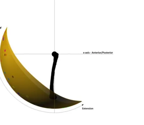
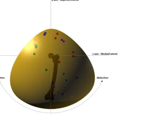
An initial ROM boundary was constructed based on the pure joint motions of flexion/extension and abduction/adduction, shown in Fig. 2. This initial representation shows an anatomical coordinate frame centred at the hip joint. As it is assumed that there are no translational effects in the hip joint, the position of the knee centre in three-dimensional space will appear as points on a sphere [68]. To construct the initial boundary, the 3D positions of the knee centre for the reference pure joint motion values of flexion, extension, abduction and adduction defined in Table 1 were plotted using eq. (2) and a curve was interpolated between these values to produce a sphere segment. The knee centre positions correlating to key points in the movement cycle of the 15 ADLs defined in Table 2 were also plotted on the 3D representation using eq. (2) using the colour code detailed.
Fig. 2 does not consider the impingement due to long-axis orientation within the boundary occurring because of internal/external rotation. To account for the effect of internal/external rotation upon the initial three-dimensional ROM representation, the axes of rotation for the researched ADLs were calculated. To maintain congruency with the right-hand rule, the researched internal/external rotation joint angles were multiplied by a factor of -1, as this would orientate the femur in the correct spatial context using eq. (1) for a left hip. The axes of rotation and the rotation about each axis were calculated using eq. (3) and eq. (4), respectively [69-71]. Taking the composite rotation matrix constructed in eq. (1) as matrix A and the fixed axis of rotation as V.
QV = [A – AT]V = . (3)
θ = arccos (4)
Page | 9 rotation axes within 15o of the transverse plane, showing that flexion/extension and abduction/adduction are the dominant joint rotations for many activities, with the exception of standing while turning the upper body away (PIVOT) and lying supine then rolling over (ROLL). To simulate the effect of daily activities upon the initial three-dimensional ROM boundary three axes of rotation were defined, eq. (5a)-(5b), based on this finding.
Transverse plane rotation axes (V1)= (5a)
15o above transverse plane axis (V2) = (5b)
15o below transverse plane axis (V3) = (5c)
Page | 10 If Matrix A takes the form =
Then , ,
, , ,
Flexion/Extension = atan2 ,
Abduction/adduction = atan2 ,
Internal/External Rotation = atan2 (6)
Page | 11
4.
Experimental validation
The three-dimensional boundaries shown in Fig. 5a-5c were investigated further. It was found that if the nominal areas of all ROM boundaries shown in gold, when overlaid, the nominal ROM boundary, shown in Fig. 5a, would include the ROM areas shown in Fig. 5b-5c and encompass all 15 defined ADLs within its boundary. To test whether this single ROM boundary is sufficient to be considered as the nominal ROM requirement, a Sawbones model of an adult male pelvis and left femur were used for experimental validation. On the pelvic model, an Orthopaedic surgeon marked the landmark points which define the Transverse Pelvic Plane (TPP) and the Anterior Pelvic Plane (APP). These planes are used as a basis from which to construct the pelvic coordinate system [8, 64]. The TPP coordinate frame uses the following landmarks to construct the pelvic coordinate frame - Anterior Superior Iliac Spines (ASISRight& ASISLeft) and Posterior Superior Iliac Spines (PSISRight& PSISLeft). Where the origin is coincident with the left hip joint centre, the z-axis runs parallel to the two ASIS with the positive direction running from left to right. The x-axis lies parallel to a line in the plane formed by the two ASIS and two PSIS, formed by the midpoint of the PSIS and orthogonal to the line formed by the two ASIS. The y-axis is orthogonal to the x-axis and the y-axis [64]. The APP coordinate frame uses the following landmarks - Anterior Superior Iliac Spines (ASISRight& ASISLeft) and Symphysis Pubis (SPUBRight & SPUBLeft). The z-axis is again parallel to a line formed between the two ASIS. The y-axis lies parallel to a line in the plane formed by the two ASIS and the two SPUB, formed by the midpoint of the SPUB and orthogonal to the line formed by the two ASIS. The z-axis is orthogonal to the x-axis and the y-axis [8].
Page | 12 Where the condyles are used in place of the epicondyles, a circular section was placed through the posterior of the medial and lateral condyles. The y-axis runs from the midpoint of the line running between the centres of the two circular condyle sections to the hip joint centre. The z-axis is perpendicular to the y-axis lying in a plane formed by the hip joint centre and the two epicondyles in the first femoral coordinate frame and the hip joint centre and the centre of the two condyle sections in the second femoral coordinate frame. The x-axis is a line perpendicular to the y-axis and the z-axis [64]. The neutral position of the femur was considered to be where the femoral and pelvic coordinate frames are coincident. Therefore, combining the different coordinate frame definitions four specifications of hip joint neutral were tested.
Page | 13 plane to be 112o, similar to average reported by [73]. This difference had a significant effect upon the resulting ROM boundary, shown in Fig. 6a-6b. Locating the femoral coordinate centre according the epicondyles or condyles had little effect on the resulting ROM boundaries. The TPP joint coordinate systems proved most representative of the nominal ROM boundary shown in Fig. 5a. Only the red area of the ROM boundary in Fig. 6a was not incorporated in the Sawbones ROM. However, all four combinations of joint coordinate systems were characterised by large degrees of adduction and extension which are not characteristic of the nominal ROM boundary. Impingement, in these circumstances did not occur at the rim of the acetabulum but rather contact with the greater trochanter of the femur with the ilium of the pelvis, or the femoral shaft with the ischium of the pelvis.
Page | 14
5.
Discussion
To have a representation of the required ROM for the hip joint which can be used as a comparator to assess prosthetic ROM so that it graphically represents any loss of motion can be a powerful tool in the treatment of hip joint disorder [17]. The hip joint range of motion boundary constructed in this study can be combined with surgical navigation to represent any loss of motion due to the prosthetic positioning in THA. As an example, if the Sawbones ROM in Fig. 6a is reinterpreted as the prosthetic ROM of a particular THA procedure. If this information was presented intra-operatively, it would give the surgeon the option to change prosthetic component options to correct the loss of motion, shown in red in Fig. 6a, so that the prosthetic ROM incorporates the entire ROM boundary. These options could include changing the modular femoral neck to alter the position of the prosthetic ROM area, or to change the acetabular liner to one with a more lateralised rotation centre to increase the size of the prosthetic ROM area.
Representing loss of motion graphically is difficult for the hip joint because of the three rotational degrees of freedom inherent in the joint, which means that there are numerous motion pathways to get to a particular position. This complexity is increased by the fact that there is an interactive nature between joints which allow an ADL to be performed in a number of different ways [20, 22]. However, being able to represent hip joint range of motion as a three dimensional continuum has the advantage of allowing the surgeon to see where impingement occurs for numerous coupled motions particularly with regard to flexion/extension and abduction/adduction. Consequently, the surgeon is not just limited to testing for discrete impingement locations, which may miss potential impingement events elsewhere during the course of a patient’s daily activities.
Page | 15 which as the experimental methodology has shown can produce significant differences with regard to the ROM boundary produced. In gait analysis measurements this presents a conflict with regard to experimental reliability and its validity. By this it is meant that a geometric defined neutral position where the pelvis and femoral coordinate frames are coincident would allow consistency and comparability of results as long as the coordinate frames are defined in the same way. However, a naturally non-orthogonal anatomical neutral position will mean that the reported amount of joint rotation in each of the anatomical planes, aligned via a geometric approach, will differ from what the patient undertakes in their day-to-day activities. The construction of the ROM boundary has attempted to address some of this ambiguity through its construction and experimental validation. The constructed boundary has been based from the pure joint motions of flexion/extension, abduction/adduction and internal/external rotation, which were obtained from clinical rather than gait analyses. Active ROM tests measure motion of the femur relative to the pelvis from a standing neutral position until the subject cannot extend their limb further, removing the ambiguity of pelvic frame definitions. The ROM boundary shows that measurements based on the TPP coordinate frame with the femoral frame coincident are more aligned with clinical measurements of ROM. The validation also signifies that caution should be applied when inferring ROM from surgical based measurements of the pelvis and femur which are based from the APP plane [8]. This coordinate frame convention can underestimate the amount of flexion within the hip joint and this can be exaggerated if the APP plane is not aligned with the whole body, which provides a further ambiguity with regard to the anatomical neutral position.
Page | 16 issues raised would allow a minimum tolerance for prosthetic ROM to be defined and allow the clinical community to maximise patient ability to perform ADL.
Word Count – 4,552
Acknowledgements
Page | 17
References
1. Enocson, A., Hedbeck, C.J., Tidermark, J., Pettersson, H., Ponzer, S., and Lapidus, L.J. Dislocation of total hip replacement in patients with fractures of the femoral neck. Acta Orthop 2009, 80, 184-189.
2. Soong, M., Rubash, H.E., Macaulay, W. Dislocation after total hip arthroplasty. J Am Acad Orthop Sur 2004, 12, 314-321.
3. Hemmerich, A., Brown, H., Smith, S., Marthandam, S., and Wyss, U. Hip, knee, and ankle kinematics of high range of motion activities of daily living. J Orthop Res 2006, 24, 770-781. 4. Mulholland, S.J., and Wyss, U.P. Activities of daily living in non-Western cultures: range of
motion requirements for hip and knee joint implants. Int J Rehabil Res 2001, 24, 191-198. 5. Kluess, D., Martin, H., Mittelmeier, W., Schmitz, K.P., and Bader, R. Influence of femoral
head size on impingement, dislocation and stress distribution in total hip replacement. Med Eng Phys 2007, 29, 465-471.
6. Nadzadi, M., Pedersen, D., Yack, H., Callaghan, J., and Brown T. Kinematics, kinetics, and finite element analysis of commonplace maneuvers at risk for total hip dislocation. J Biomech 2003, 36, 577-591.
7. Khan, M.A., Brakenbury, P., and Reynolds, I. Dislocation following total hip replacement. J Bone Joint Surg [Br] 1981, 63, 214-218.
8. DiGioia, A.M., Jaramaz, B., Blackwell, M., Simon, D.A., Morgan, F., Moody, J.E., Nikou, C., Colgan, B.D., Aston, C.A., Labarca, R.S., Krischell, E., and Kanade, T. The Otto Aufranc Award. Image guided navigation system to measure intraoperatively acetabular implant alignment. Clin Orthop Relat R 1998, 355, 8-22.
9. Lewinnek, G., Lewis, J., Tarr, R., Compere, C., and Zimmerman, J. Dislocations after total hip-replacement arthroplasties. J Bone Joint Surg [Am] 1978, 60, 217-220.
Page | 18 11. Woo, R.Y., and Morrey, B.F.. Dislocations after total hip arthroplasty. J Bone Joint Surg [Am]
1982, 64, 1295-1306.
12. Scifert, C.F., Noble, P.C., Brown, T.D., Bartz, R.L., Kadakia, N., Sugano, N., Johnston, R.C., Pedersen, D.R., and Callaghan, J.J. Experimental and computational simulation of total hip arthroplasty dislocation. Orthop Clin N Am 2001, 32, 553-567.
13. D'Lima, D.D., Urquhart, A.G., Buehler, K.O., Walker, R.H., and Colwell, C.W. The Effect of the Orientation of the Acetabular and Femoral Components on the Range of Motion of the Hip at Different Head-Neck Ratios. J Bone Joint Surg [Am] 2000, 82, 315-321.
14. Nadzadi, M.E., Pedersen, D.R., Callaghan, J.J., and Brown, T.D. Effects of acetabular component orientation on dislocation propensity for small-head-size total hip arthroplasty. Clin Biomech 2002, 17, 32-40.
15. Sariali, E., Lazennac, J.Y., Khiami, F., and Cantonné, Y. Mathematical evaluation of jumping distance in total hip arthroplasty: Evaluation of abduction angle, femoral head offset and head diameter. Acta Orthop 2009, 80, 277-282.
16. Seki, M., Yuasa, N., and Ohkuni, K. Analysis of optimal range of socket orientations in total hip arthroplasty with use of computer-aided design simulation. J Orthop Res 1998, 16, 513-517.
17. Thornberry, R.L., and Hogan, A.J. The Combined Use of Simulation and Navigation to Demonstrate Hip Kinematics. J Bone Joint Surg [Am] 2009, 91, 144-152.
18. Widmer, K.H., and Zurfluh, B. Compliant positioning of total hip components for optimal range of motion. J Orthop Res 2004, 22, 815-821.
Page | 19 20. Johnston, R.C., and Smidt, G.L. Hip motion measurements for selected activities of daily
living. Clin Orthop Relat R 1970, 72, 205-215.
21. Ko, B.H., and Yoon, Y.S. Optimal orientation of implanted components in total hip arthroplasty with polyethylene on metal articulation. Clin Biomech 2008, 23, 996-1003. 22. Davis, K.E., Ritter, M.A., Berend, M.E., and Meding, J.B. The Importance of Range of Motion
after Total Hip Arthroplasty. Clin Orthop Relat R 2007, 465, 180:184.
23. Ahlberg, A., Moussa, M., and Al-Nahdi, M,. On geographical variations in the normal range of joint motion. Clin Orthop Relat R 1988, 234, 229-231.
24. Amstutz, H.C., Lodwig, R., Schurman, D., and Hodgson, A. Range of motion studies for total hip replacements: a comparative study with a new experimental apparatus. Clin Orthop Relat R 1975, 111, 124-130.
25. Barrack, R.L., Lavernia, C., Ries, M., Thornberry, R., and Tozakoglou, E.. Virtual reality computer animation of the effect of component position and design on stability after total hip arthroplasty. Orthop Clin N Am 2001, 32, 569-577.
26. Burroughs, B.R., Golladay, G.J., Hallstrom, B., and Harris, W.H. A novel constrained acetabular liner design with increased range of motion. J Arthroplasty 2001, 16, 31-36. 27. Burroughs, B.R., Hallstrom, B., Golladay, G.J., Hoeffel, D., and Harris W.H. Range of Motion
and Stability in Total Hip Arthroplasty With 28-, 32-, 38-, and 44-mm Femoral Head Sizes An In Vitro Study. J Arthroplasty 2005, 20, 11-19.
28. Boone, D.C., and Azen, S.P. Normal range of motion of joints in male subjects. J Bone Joint Surg [Am] 1979, 61, 756-759.
Page | 20 30. Hagio, K., Sugano, N., Nishii, T., Miki, H., Otake, Y., Hattori, A., Suzuki, N., Yonenobu, K.,
Yoshikawa, H., and Ochi, T. A novel system of four-dimensional motion analysis after total hip arthroplasty. J Orthop Res 2004, 22, 665-670.
31. Jaramaz, B., DiGioia, A., Blackwell, M., and Nikou, C. Computer assisted measurement of cup placement in total hip replacement: Computer assisted orthopaedic surgery: Medical robotics and image guided surgery. Clin Orthop Relat R 1998, 354, 70-81.
32. Kessler, O., Patil, S., Stefan, W., Mayr, E., Colwell, C.W., and D'Lima, D.D. Bony impingement affects range of motion after total hip arthroplasty: A subject-specific approach. J Orthop Res 2008, 26, 443-452.
33. Krushell, R.J., Burke, D.W., and Harris, W.H. Elevated-rim acetabular components: Effect on range of motion and stability in total hip arthroplasty. J Arthroplasty 1991, 6, S53-S58. 34. Miki, H., Yamanashi, W., Nishii, T., Sato, Y., Yoshikawa, H., and Sugano, N. Anatomic hip
range of motion after implantation during total hip arthroplasty as measured by a navigation system. J Arthroplasty 2007, 22, 946-952.
35. Pedersen, D., Callaghan, J., and Brown, T. Activity-dependence of the "safe zone" for impingement versus dislocation avoidance. Med Eng Phys 2005, 27, 323-328.
36. Piazza, S.J., Erdemir, A., Okita, N., and Cavanagh, P.R. Assessment of the functional method of hip joint center location subject to reduced range of hip motion. J Biomech 2004, 37, 349-356.
37. Roaas, A., and Andersson, G.B.J. Normal range of motion of the hip, knee and ankle joints in male subjects, 30-40 years of age. Acta Orthop 1982, 53, 205-208.
38. Roach, K.E., and Miles, T.P. Normal hip and knee active range of motion: the relationship to age. Phys Ther 1991, 71, 656-665.
Page | 21 40. Sun, H., Inaoka, H., Fukuoka, Y., Masuda, T., Ishida, A., and Morita, S. Range of motion
measurement of an artificial hip joint using CT images. Med Biol Eng Comput 2007, 45, 1229-1235.
41. Widmer, K.H., and Majewski M. The impact of the CCD-angle on range of motion and cup positioning in total hip arthroplasty. Clin Biomech 2005, 20, 723-728.
42. Yoshimine, F. The safe-zones for combined cup and neck anteversions that fulfil the essential range of motion and their optimum combination in total hip replacements. J Biomech 2006, 39, 1315-1323.
43. American Academy of Orthopaedic Surgeons. Joint motion: method of measuring and recording, 1965 (Chicago).
44. Cailliet, R. Soft tissue pain and disability, 1978, pp 196:215 (Philidelphia: FA Davis Co). 45. Cole, T.M. Goniometry: The measurement of joint motion, 1971, pp 40-44 (WB Saunders). 46. Costigan, P.A., Deluzio, K.J., and Wyss, U.P. Knee and hip kinetics during normal stair
climbing. Gait Posture 2002, 16, 31-37.
47. Daniels, L., and Worthingham, C. Muscle testing: techniques of manual examination, 1972 (WB Saunders).
48. Gajdosik, R.L., and Bohannon, R.W. Clinical measurement of range of motion: review of goniometry emphasizing reliability and validity. Phys Ther 1987, 67, 1867-1872.
49. Green, W.B.B. [E], and Heckman, J.D. [E]. The clinical measurement of joint motion, 1994, pp 99-114 (Rosemont: American Academy of Orthopaedic Surgeons).
50. Hoppenfeld, S., and Hutton, R. Physical examination of the spine and extremities, 1976 (Prentice Hall).
51. James, B., and Parker, A.W. Active and passive mobility of lower limb joints in elderly men and women. Am J Phys Med Rehab 1989, 68, 162-167.
Page | 22 53. Kendall, H.O., Kendall, F.P., and Wadsworth, G.E. Muscles testing and function, 1971
(Baltimore).
54. Kummer, F.J., Shah, S., Iyer, S., and DiCesare, P.E. The effect of acetabular cup orientations on limiting hip rotation. J Arthroplasty 1999, 14, 509-513.
55. Mohr, T. Musculoskeletal Analysis: the Hip, 1989, pp 369-380 (Lippincott, 1989).
56. Rowe, P., Myles, C., Walker, C., and Nutton, R. Knee joint kinematics in gait and other functional activities measured using flexible electrogoniometry: how much knee motion is sufficient for normal daily life? Gait Posture 2000, 12, 143-155.
57. Weiss, J.M., Noble, P.C., Conditt, M.A., Kohl, H.W., Roberts, S., Cook, K.F., Gordon, M.J., and Mathis, K.B. What functional activities are important to patients with knee replacements? Clin Orthop Relat R 2002, 404, 172-188.
58. Johnston, R.C., and Smidt, G.L. Measurement of hip joint motion during walking: evaluation of an electrogoniometric method. J Bone Joint Surg [Am] 1969, 51, 1083-1094.
59. Kadaba, M., Ramakrishnan, H., and Wootten, M. Measurement of lower extremity kinematics during level walking. J Orthopaedic Res 1990, 8, 383:392.
60. Noble, P.C., Sugano, N., Johnston, J.D., Thompson, M.T., Conditt, M.A., Engh, C.A., and Mathis, K.B. Computer simulation: how can it help the surgeon optimize implant position? Clin Orthop Relat R 2003, 417, 242-252.
61. Nonaka, H., Mita, K., Watakabe, M., Akataki, K., Suzuki, N., Okuwa, T., and Yabe, K. Age-related changes in the interactive mobility of the hip and knee joints: a geometrical analysis. Gait Posture 2002, 15, 236-243.
62. Svenningsen, S., Terjesen, T., Auflem, M., and Berg, V. Hip motion related to age and sex. Acta Orthop 1989, 60, 97-100.
Page | 23 64. Wu G., Siegler S., Allard P., Kirtley C., Leardini, A., Rosenbaum D., et al. ISB
recommendation on definitions of joint coordinate system of various joints for the reporting of human joint motion—part I: ankle, hip, and spine. J Biomech 2002, 35, 543-548.
65. Cappozzo, A., Della Croce, U., Leardini, A., and Chiari, L. Human movement analysis using stereophotogrammetry – Part 1: theoretical background. Gait Posture 2005, 21, 186-196. 66. Chezea, L., Dumasa, R., Comteta, J.J., Rumelharta, C., and Fayeta, M. A joint coordinate
system proposal for the study of the trapeziometacarpal joint kinematics. Comput Method Biomech 2009, 12, 277-282.
67. Cheng, P.L. Joint rotation between two attitudes in the spherical rotation coordinate system. J Biomech 2004, 37, 1475-1482.
68. Camomilla, V., Cereatti, A., Vannozzi, G., and Cappozzo, A. An optimized protocol for hip joint centre determination using the functional method. J Biomech 2006, 39, 1096-1106. 69. Cheng, P.L., Nicol, A.C., and Paul, J.P. Determination of axial rotation angles of limb
segments-a new method. J Biomech 2000, 33, 837-843.
70. Heading, J.Matrix theory for physicists, 1958 (Longmans, Green).
71. Kuipers, J.B. Quaternions and rotation sequences: A primer with applications to orbits, aerospace, and virtual reality, 1999, 1st Edition (Princeton University Press).
72. Murray, R.M., Li, Z., Sastry, S., and Sastry, S.S. A mathematical introduction to robotic manipulation, 1994 (CRC Press).
Page | 24
Tables
Table 1. Recommended reference and distribution figures for pure joint motion of the hip.
Flexion Extension Abduction Adduction
Internal
Rotation
External
Rotation
Reference Value 120o 30o 45o 35o 45o 45o
+1 SD 130o 37.5o 55o 40o 52.5o 52.5o
Page | 25 Table 2. Defined activities of daily living.
Colour Code Description
FXLG Sitting on the floor cross-legged [3].
KNEEL 1 Kneeling with ankles dorsi-flexed [3].
KNEEL 2 Kneeling with ankles plantar-flexed [3].
LEVEL Level walking [59].
PIVOT Standing while turning the upper body away [6, 21].
ROLL Lying supine and rolling over, for example, when in bed [21].
SQUAT 1 Squatting with feet flat [3].
SQUAT 2 Squatting balancing on flexed toes [3].
SSL Stand-sit-stand from a low seat (~40cm high) [6, 21].
SSN Stand-sit-stand from a normal seat (~46cm high) [6, 21].
STAIR Ascending and descending stairs [20].
STOOP Standing then bending to retrieve an object from floor [6, 21].
SWING Swinging leg back and forth [21].
TIE Sitting on a normal seat and bending to tie shoe laces [6, 20].
Page | 26
Captions for illustrations
Fig. 1: The systematic review search strategy.
Fig. 2: Initial three dimensional range of motion representation.
Fig. 2a: View of the initial range of motion boundary in the sagittal plane.
Fig. 2b: View of the initial range of motion boundary in the coronal plane.
Fig. 3: Deviation of ADL fixed axis of rotation away from the transverse plane.
Fig. 4: Knee centre joint angles in the coronal-transverse plane, impinged motion shown in red.
Fig. 5: Effect of internal/external rotation of the nominal range of motion boundary.
Fig. 5a: Transverse plane rotation axis nominal boundary plot.
Fig. 5b: 15o above transverse plane axis nominal boundary plot.
Fig. 4c: 15o below transverse plane axis nominal boundary plot.
Fig. 6: Experimental validation of the nominal range of motion boundary.
Fig. 6a: Comparison with the transverse pelvic plane coordinate frame.
Page | 27
List of notations
ADL – Activities of daily living.
APP – Anterior pelvic plane.
OA – Osteoarthritis.
RA – Rheumatoid arthritis.
ROM – Range of motion.
THA – Total hip arthroplasty.
Fig. 1: colour
Fig. 2a: colour
Fig. 2b: colour
Fig. 3: colour
Fig. 4: colour
Fig. 5a colour
Fig. 5b colour
Fig. 5c colour
Fig. 6a colour
Fig. 6b colour