Abstract—Mass loading has been one of the major parameter need to be consider before any of a surface acoustic wave devices can be fabricate. In this paper a finite element method (FEM) study of the mass loading on gallium phosphate surface acoustic wave resonator was done for high temperature sensing applications. A comparison with the previous experimental work has shown that FEM can be used to determine the effect of mass loading to the center frequency of the surface acoustic wave resonator.
Index Terms—Gallium Phosphate, Mass loading, Surface Acoustic Wave Resonator. Resonant frequency
I. INTRODUCTION
Surface Acoustic Wave device (SAW) has been used as the main principle for device that has been successfully applied to the processing of electrical signal for more than 3 decades. They are particularly prevalent in the telecommunication industry and wireless application, especially as bandpass filters in both IF and RF section, resonator because of their high performance, small size, rigorous and high reproducibility. Also due to their high accuracy and crystal stability over time, SAW devices are suitable for sensor application such as pressure, temperature, and strain sensors. The most common structure used for implementation of SAW sensors is the SAW delay line and the SAW resonator. In both, the influence of the measured quantity on the acoustic wave phase propagation speed, v, is utilized for sensor applications. Both delay line and resonator be making as single-port or two-port devices. A SAW delay line is characterized by a propagation path between two separate interdigital transducers (IDTs): the first is working as a transmitting transducer and the second as a receiving transducer to convert the SAW back to the electrical domain.
Manuscript received October 9, 2008. This work was supported in part by the Ministry of High Education under Fundamental Research Grant Scheme FR.
Corresponding author. M. N. Hamidon is with the Department of Electical and Electronic Engineering, Faculty of Engineering, Universiti Putra Malaysia, 43400 UPM Serdang, Malaysia. phone : +603-89466309: fax: +603-89466327; e-mail: [email protected]
S. A. Mousavi and M. M. Isa were also with the Department of Electical and Electronic Engineering, Faculty of Engineering, Universiti Putra Malaysia, 43400 UPM Serdang. (e-mail: [email protected] and [email protected] )
A. Ismail and M. A. Mahdi with the Department of Computer and Communication System Engineering, Faculty of Engineering, Universiti Putra Malaysia, 43400 UPM Serdang. (e-mail: [email protected], [email protected] )
Meanwhile, a resonator uses one IDT structure in the centre between two gratings known as reflectors (are obtained through the use of metal strips or grooves localized on the acoustic propagation path), reflecting at the characteristic frequency, f, which also known as resonance frequency. This resonance frequency is such that energy stored in between the reflectors (known as the resonance cavity) is at a minimum and will be effect due to mass loading.
Mass loading is an effect that results from the modification of the boundary conditions on the major surface of the transducer due to the presence of the electrodes. This effect can be separated into three primary categories [1]. The first, known as inertial effects due to the electrodes, is commonly used as a means of frequency adjustment, whereby adding mass to the surface provides a convenient means of frequency adjustment. The thin layer of electrodes appears as lumped masses of mass per unit area, σe determined by the
layer density, ρe and thickness, te .
σe = ρete (1)
So by adding mass to the surface, this provides a convenient means of frequency adjustment. It is also a significant source of frequency ageing because of contamination, especially in harsh conditions. A smaller inertial effect is an alteration of the resonator frequency-temperature behaviour as the metallisation thickness is varied [2].
The second effect is energy trapping, where the mass loading combined with the size of the electrode will play an important part in energy trapping under the electrodes. They create regions with different cut-off frequencies, which will allow the confinement of vibrational energy. In particular, the possibility exists to limit the number of trapped modes to only one, by carefully controlling the mass loading and the electrode dimensions. This was first studied by Bechmann and the critical ratio of the electrode dimension to the plate thickness required to trap only one mode is known as Bechmann’s number [3]. It is important for the energy of the trapped mode to be concentrated under the electrodes, which gives rise to a strong resonator response, whereas the modes that are not trapped can propagate over the whole resonator.
The final effect is the effect due to the intrinsic stresses in the electrode layers and mechanical strains due to the thermal expansion mismatch of the electrode-substrate interface. This effect is smaller than the pervious two at low temperatures. A study has shown that the change in the first order of temperature coefficient of frequency can be calculated as a function of increasing mass loading for the case of a gold electrode [4], where the compressive stresses are developed
Finite Element Method on Mass Loading Effect
for Gallium Phosphate Surface Acoustic Wave
Resonators
in a quartz at the rate of 104 N·m -2 per Kelvin per percent of mass loading.
The relative magnitude of the mass loading is expressed in terms of the ratio R, which is the electrode mass per unit area to the mass per unit area of the transducer (such as the resonator).
h s
e R
ρ σ
= (2)
where ρs(kg·m
-3
) and h(m) are the mass density and height of the piezoelectric substrate. The relationship between the mass loading and the resonance frequency (of quartz crystal) was first investigated by Sauerbery in 1957, where he found that the fundamental resonance frequency was linearly related to the increased mass, as shown in (3) below
f e f f m
m e
m −
= −
(3)
where me and fe are the mass and frequency after deposition; m and f are the unloaded quartz crystal and frequency. This as been further studied by Lewis [5], in which he found that
f e f f h s
e t
e = −
ρ ρ
(4)
So from (2) and (4) the mass loading can also be written as
f e f f
R = − (5)
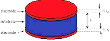
[image:2.595.71.260.527.598.2]All of these equations (2) to (5) refer to the typical piezoelectric plate resonator consisting of a piezoelectric substrate disk such as quartz with metallic electrodes top and bottom, as shown in Fig. 1.
Fig. 1. Piezoelectric plate resonator
In paper, the electrodes of the resonator are made from an IDT grating and consist of two different layers of material (Pt with an underlayer of different material such as Zr). So from the results of the earlier studies [6], (5) is modified to become:
2
.
⎟
⎟
⎠
⎞
⎜
⎜
⎝
⎛
Σ =λ ρ
i t i const
R (6)
where ρi and ti are the density and height of the layer forming the IDT grating and the constant of the (6) is 0.455 (g·cm -3)-2, which was calculated from the research by Bigler and Briot for surface transverse waves with Al or Au on gallium phosphate.
Gallium phosphate (GaPO4), is a promising piezoelectric
material for high technology applications in harsh environments [7]. GaPO4 has a structure similar to α-quartz
but a better choice for high temperature piezoelectric devices than quartz [8]. They both belongs to the point group 32 and only that for GaPO4 structure the silicon atoms from SiO2
being replaced alternately with phosphorus ad gallium. The alpha-beta phase transition to the point group 32, with the occurrence of incommensurable phases common to quartz and other quartz homeotypes like AlPO4, does not occur in
GaPO4 while some advantageous properties, such as the
stiffening of elastic stiffness constant c66, are still conserved.
These properties are believed to be connected with the alpha-beta transition due to the rotation mechanism of the tilted tetrahedrons, which is essentially the same as in all crystals of this group. At 970oC an irreversible reconstructive transition occurs to the so-called beta-cristobalite phase. The resulting density from the molecular weight and the unit cell volume is 3570 kg·m -3. The melting point, heat capacity and the electrical resistivity at room temperature are 1670oC, 560 J/ kg·K and over 1014 cm respectively [9]. The high density leads to a lower acoustic velocity, which have a potential for reducing the size and the cost of the devices. Meanwhile, due to high piezoelectric coefficient (double, compared to quartz) leads to a higher electromechenical coupling coefficient of GaPO4 with better results in SAW devices.
II. FINITE ELEMENT METHOD BASED ON CELL MODEL There have been several studies to develop models to simulate mechanical and electrical behavior of SAW devices [10]. Numerical method such as finite element method (FEM) can be used to analyze the infinite grating of IDT in SAW [11]. It is essential to develop full scale three-dimensional (3-D) model of SAW devices to better elucidate their operational mechanism of them, where the FEM can be the accurate method. However FEM suffers from immense computational expense if an extremely precise data are demanded. Moreover, the FEM allow the reduction of the periodic simulation domain to one base cell [12]. The computation of one period of the infinite structure with the application of inverted periodically boundary condition allows us the analysis of the total device geometry [11, 13].
This paper investigates a 3-D FEM applied for a SAW resonator containing a novel piezoelectric, GaPO4 as a
Table 1. Sample with different platinum thickness
Sample Platinum thickness
(nm)
Total thickness (nm)
W1 72 82
W2 75 85
W3 94 104
A. SAW Resonator Structures
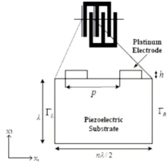
As mention before, the geometrical structure of the SAW resonator for the studies consists of IDT and reflector as shown in Fig. 2. The IDT which made of metal electrodes or fingers are connected by bus-bar, and the length where they are overlap between each other a known as the acoustic aperture, W, of the IDT. The acoustic aperture is determined the impedance level which is roughly inversely proportional to the acoustic aperture.
[image:3.595.40.296.70.133.2]The reflector electrodes are typically shorted and connected to the ground to avoid regeneration of SAW resonator [14]. The pitch, p is defined as the width of one finger, a, and the gap distance between the fingers. The gaps serve to provide a controlled phase shift of the propagation acoustic wave [15]. The propagation of acoustic waves in piezoelectric media depends on the substrate material properties, the crystal cut and the structure of the electrodes. In general, coupling is strong between incident and reflected waves, if the period of the grating is close to half of the wavelength (λ =2p) [14].
Fig. 2. Schematic representation of acoustical element of one-port SAW resonator
B. Model Descriptions
The phenomenon of surface acoustic wave propagation was first reported by Lord Rayleigh in 1885 and was named after hin [16]. These waves propagate along the free surface of a semi-infinite elastic substrate whose amplitude decays exponentially with the substrate depth, and penetration depth is just over one wavelength in piezoelectric materials which are strictly confined to the sagittal plane [14, 17] as shown in Fig. 3. This displacement has in a surface-normal or longitudinal component and surface parallel or vertical transverse component with respect to the direction of wave propagation. Therefore, the particle in the upper surface takes elliptical path and having both the component.
Fig. 3. (a) the sagittal plane and, (b) cross view of the substrate particle displacement caused by the SAW The displacement of surface u1, u2, u3 along x1, x2, x3 directions for Rayleigh wave is given by (7).
u1 = [A1exp(-b1x3) + A2exp(-b2x3)exp(jk(x1-υt)] (7a)
u2 = 0 (7b) u3 = [(-b1/jk)A1exp(-b1x3) + (jk /b2)A2exp(-b2x3)exp(jk(x1-υt)] (7c)
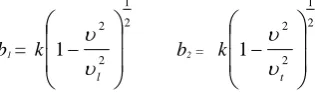
where A1, A2are amplitudes, and b1, b2are equal to:
b1=
2 1
2 2
1
⎟
⎟
⎠
⎞
⎜
⎜
⎝
⎛
−
l k
υ υ
b2 =
2 1
2 2
1
⎟
⎟
⎠
⎞
⎜
⎜
⎝
⎛
−
t k
υ υ
υl and υtare longitudinal and transverse wave velocities, k is the wave number.
[image:3.595.314.472.379.426.2] [image:3.595.50.280.401.516.2]Fig. 4. Base cell geometry of devices
Meanwhile the harmonic response of the device, where the governing differential equation which define the mechanical and electrical properties in the volume have to be established for the amplitudes of the mechanical displacement, uiand the electrical scalar potential, Φ in (8a) and (8b) in the Cartesian system [19]. ∑ ∂ ∂ = ∑ ⎟ ⎟ ⎟ ⎠ ⎞ ⎜ ⎜ ⎜ ⎝ ⎛ ∑ ∂ ∂ ∂ + ∂ ∂ Φ ∂ j t i u
k i xj xk
k u E ijkl C k x j x kij e 2 2 2 2
ρ (8a)
∑ ∑ = ⎟ ⎟ ⎟ ⎠ ⎞ ⎜ ⎜ ⎜ ⎝ ⎛ ∑ ∂ ∂ ∂ − ∂ ∂ Φ ∂
i j k xi xk
j u ijk e j x i x S ij 0 2 2
ε for D = 0
(8b)
where S, E, D, Φ, C, e, ρ, ε and u are the strain, electric filed, dielectric displacement, electrical potential, elastic constant, piezoelectric constant, density, dielectric permittivity and mechanical displacement.
C. Boundary Conditions
As the SAW devices structures are periodic in nature, appropriate periodic boundary conditions are applied using the following equation [20]:
⎪
⎭
⎪
⎬
⎫
Γ
=
Γ
−
=
+
−
=
+
)
,
(
)
,
(
)
2
exp(
)
(
)
(
)
2
exp(
)
(
)
(
V
u
V
u
n
i
x
V
np
x
V
n
j
x
u
np
x
u
L R i i i iρ
πγ
πγ
(9)Meanwhile from Fig. 4, the surface conditions on the sides of the SAW resonator a fixed at the bottom, free at the top and periodic boundary for the left and right [20]. These conditions are then can be written as follows:
top surface : traction free left and right boundary :
⎩
⎨
⎧
=
=
R L R LU
U
φ
φ
(10) bottom surface : Fixedwhere UL, UR and φL, φR are displacement and potential at left
and right boundaries respectively.
By considering periodic boundary, it can be conclude that the right periodic boundary degree of freedom, ΓR, is equal to
the left periodic boundary degree of freedom, ΓR (see Fig. 4)
[11, 12]. In the simulation a 1 V of electrical potential is considered onto the electrodes.
D. Material Properties
A trigonal crystal symmetry such as GaPO4 crystal with
(90o
,5o
,0o
[image:4.595.293.553.252.436.2]) Euler angle set was applied as in Table 2 [21]. Table 2. Properties of GaPO4 crystal with (90o
, 5o
, 0o
) Euler angle
GaPO4
Elastic constant (1011 N·m -3) C11 0.6635 C12 0.2165 C13 0.1456 C33 1.0131 C44 0.3780 Piezoelectric constant (C·m -2) e11 0.2238
e14 0.1235 Relative dielectric constant S
11
ε
5.154S 33
ε
5.818Mass density (103 kg·m -3) ρ 3.57 Free surface velocity (m·s -1) υo 2538.9 Electromechanical coupling
coefficient (%)
K2 0.184
In Table 2, [C]6x6, [e]6x3, [ε]3x3, and ρ are the stiffness, piezoelectric-stress coupling matrix, electrical permittivity matrix and density of GaPO4respectively.
Platinum (Pt) and Zirconium (Zr) are used as the electrode material and under-layer respectively. The properties of these metal are written in Table 3.
Table 3. Properties of metal used for the electrode
Metal Youngs Modulus, Y
(GPa)
Density, ρ
( kg·m -3)
Poisson’s ratio
Melting point
(oC)
Pt 168 21440 0.38 1768
Zr 68 6511 0.34 1855
[image:4.595.48.252.333.448.2]III. RESULT AND DISCUSSION
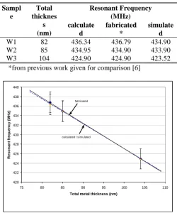
By observing the impedance of SAW resonator simulated using FEM, the change in resonant frequency with different total metal thickness can be observed and these are summarized in Table 4 and Fig. 5. In Fig. 6, the resonant frequencies are then plotted again the calculated, fabricated and simulated. It was found that these three graphs have a significant agreement. It also shows that the values of the simulated and calculated were nearly overlapping each other.
[image:5.595.303.558.166.471.2]Fig. 5. Impedance of SAW resonator simulated using FEM Table 4. Resonant frequency vs. total metal thickness
Resonant Frequency (MHz) Sampl
e
Total thicknes
s (nm)
calculate d
fabricated *
simulate d
W1 82 436.34 436.79 434.90
W2 85 434.95 434.90 433.90
W3 104 424.90 424.90 423.52 *from previous work given for comparison [6]
calculated / simulated fabricated
420 422 424 426 428 430 432 434 436 438 440
75 80 85 90 95 100 105 110
Total metal thickness (nm)
R
eson
a
n
t f
re
q
uency
(M
H
z
)
Fig. 6. Resonant frequency vs. total metal thickness
In Table 5 and Fig. 7, the relative mass loading effect (expresses as a percentage change) due to different thickness are plotted against the calculated, fabricated and simulated resonant frequencies of the SAW resonator. It was found that
by using the FEM simulated result will also shown the effect of the mass loading to the resonant frequency of the devices significantly. This mean that FEM can be used to verified of the thickness of the metal needed to achieve required operation frequency with any types of piezoelectric material. This can be done if all the parameters and properties of the needed material are known.
[image:5.595.45.288.174.360.2]
Table 5. Mass loading effect vs. total metal thickness
Mass Loading Effect (%)
Sampl e
Total thicknes
s (nm)
calculate d
Fabricated *
simulate d
W1 82 3.755 3.658 3.757 W2 85 4.061 4.070 4.064 W3 104 6.280 6.281 6.281
*from previous work given for comparison [6]
calculated/simulated
fabricated
3 3.5 4 4.5 5 5.5 6 6.5 7
75 80 85 90 95 100 105 110
Total metal thickness (nm)
M
a
ss l
o
ad
in
g
, R
(
%
)
Fig. 7. Mass loading vs. resonant frequency
IV. CONCLUSIONS
In this work, a model on finite element method (FEM) for mass loading effect has been presented and compared with the literature. It was found that by using the FEM, the desired resonant frequency of SAW resonator could be predicted for each case.
ACKNOWLEDGMENT
This work was supported by Ministry of High Education under Fundamental Research Grant Scheme (FRGS) with project number of 07-10-07-412FR.
REFERENCES
[1] G. Mallikarjun, J. Kosinski and A. Ballato, “Mass loading measurements of quartz crystal palates),” in Proceeding IEEE Frequency Control Symposium, 1989, pp. 365-371.
[2] A. Ballato, J. Kosinski and T. Lukaszek, “Temperature and angular variations of piezoelectric coupling in quartz,” in Proceeding IEEE Ultrasonics Symposium, 1988, pp. 353-356.
[3] T. R. MeekerH. Poor, Theory and Properties of Piezoelectric resonators and Waves. Academic Press, 1985.
[image:5.595.44.295.402.703.2][5] O. Lewis, “Relstionship of resonant frequency of quartz crystal to mass loading,” in Proceeding IEEE Frequency Control Symposium, 1975, pp. 5-9.
[6] M. N. Hamidon, V. Skarda, N. M. White, F. Krispel, P. Krempl, M. Binhack and W. Buff, “Fabrication of high temperature surface acoustic wave devices for sensor applications,” Sensors and Actuators A, vol. 123-124, 2005, pp. 403-407.
[7] M. N. Hamidon, V. Skarda, N. M. White, F. Krispel, P. Krempl, M. Binhack and W. Buff, “High-temperature 434 mhz surface acoustic wave based on Gapo4,” IEEE Trans. on Ultrasonic, Ferroelectrics and Frequency Control, vol.53, no. 12, Dec 2006, pp. 2465 – 2470. [8] C. Bonjour, G. Martin, A. Zarembovitch, E. Bigler, D. Palmier, R.
Gohier and E. Philippot, “New results on the thermal sensitivity of bulk and surface modes of gallium orthophosphate gapo4,” in Proceeding IEEE Ultrasonics Symposium, 1995, pp. 605-610.
[9] H. Thanner, W. Wallnofer, C. Reiter, P. W. Krempl and P. M. Worsch, “Material properties of gapo4 and their relevance application,” Annales de Chimie Science des Materiaux, vl.26, no.1, 2001, pp. 91-94. [10] S. Ballandras, A. Reinhardt, V. Laude, A. Soufyane, S. Camou and W.
Daniau, “Simulations of surface acoustic wave devices built on stratified media using a mixed finite element/boundary integral formulation,” Journal of Applied Physics, vol. 96, 2004, pp. 7731-7741.
[11] M. Hofer, N. Finger, G. Kovacs, J. Schoberl, S. Zaglmayr, U. Langer and R. Lerch, “Finite element simulation of wave propagation in periodic piezoelectric saw structure,” IEEE Trans. on Ultrasonic, Ferroelectrics and Frequency Control, vol. 53, 2006, pp. 1192-1201. [12] M. Hofer, N. Finger, G. Kovacs, J. Schoberl, U. Langer and R. Lerch,
“Finite element simulation of bulk and surface acoustic wave (saw) interaction in saw devices,” in Proceeding IEEE Ultrasonics Symposium, 2002, pp. 53-56.
[13] R. Lerch “Simulation of piezoelectric devices by two- and three-dimensional finite elements,” IEEE Trans. on Ultrasonic, Ferroelectrics and Frequency Control, vol. 37, 1990, pp. 233-247. [14] D. Morgan, Surface Acoustic Wave Filters with Application to
Electronic Communication and Signal Processing, Elesevier, 2007. [15] C. C. W. Ruppel and T. Fieldly, Advances in Surface Acoustic Wave
Technology, Systems and Applications, vol. 1, World Science, 2000. [16] Lord Rayleigh, “On waves propagating along the plane surface of an
elastic solid,” in Proceeding London Math. Society, vol. 7, 1885, pp. 4-11.
[17] E. Dieulesaint and D. Royer, Elastic Waves in Solids, Great Britain, Wiley-Interscience Publication, 1980.
[18] J. W. Gardner, V. K. Vardan and O. O. Awadelkarim, Microsensors, MEMS and Smart Devices, Wiley & Sons, 201.
[19] D. P. Morgan, Surface-Wave Devices for Signal Processing, Elesevier, 1991, pp. 17-19.
[20] M. Buchner, W. Ruile, A. Dietz and R. Dill, “Fem analysis of the reflection coefficient of saws in an infinite periodic array,” in Proceeding IEEE Ultrasonics Symposium, 1991, pp. 371-375. [21] R. Fachberger, G. Bruckner, R. Hauser and L. Reindl, “Wireless saw