An Efficient Scheduling Scheme to Enhance the Capacity
of VoIP Services in Evolved UTRA Uplink
Yong-Seok Kim
∗Abstract—In this paper, an efficient scheduling scheme is proposed to increase the available capacity of VoIP services over Evolved UTRA uplink. On top of the advantages of persistent scheduling, the pro-posed scheme adaptively share the resources of two VoIP users to get early-termination gain of dynamic scheduler. Through system-level simulations, the per-formance of the proposed algorithm is evaluated in terms of the capacity enhancement of VoIP services. Comparisons with the original persisten scheduling and the HSUPA scheduler reveal that the proposed scheme increases the capacity of VoIP services up to 20%.
Keywords: VoIP, an adaptive resource sharing, persis-tent scheduling, E-UTRA uplink
1
Introduction
Evolved universal terrestrial radio access (E-UTRA), which is known as long term evolution (LTE) of third-generation cellular system, is being specified by the third generation partnership project (3GPP). In September 2006, the study item of the LTE has been completed and the corresponding work item was scheduled to be finalized within about one and a half years, i.e. the second half of 2007, so that the subsequent initial deployment can be possible in the year of 2009 or 2010. The E-UTRA is regarded as the preliminary version of next generation wireless communication system because of its capability to satisfy demand for higher user bit rates [1], [2]. In order to obtain such higer user bit rates, the E-UTRA is be-ing designed by only packet-switched (PS) network with-out circuit mode, requiring all the available LTE services should be implemented on top of internet protocol (IP). At this point, the transmission of real-time data such as voice traffic through PS IP network becomes arguably the hottest issue today because voice over IP (VoIP) has high visibility in consumer space.
Managing such real-time data transmission, schedul-ing algorithm at medium access control layer can be a core function because the algorithm directly controls the level of quality-of-service (QoS). As a basic scheduling scheme for packet-based services, proportional fairness (PF) scheduler was designed to support the high data
∗LTE Advanced Tech. Lab. Telecommunication R&D Center,
Telecommunication Network Business, Samsung Electronics, Korea Email: [email protected]
rate of 3GPP2 wireless system in [3]. The PF scheduler provides effectiveness from the view point of throughput and fairness by judiciously selecting frames based on the average and the instantaneous data rate of each user. Be-cause of its simple yet effective scheduling capability, the scheme is still being used in the LTE as dynamic sched-uler. However, such dynamic scheduler could provide lim-ited performance for some delay sensitive real-time ser-vices, in that the scheduling algorithm passed over delay constraint in its frame prioritization.
To cope with such delay problem and to satisfy the spe-cific QoS parameter of maximum allowable service delay, the author proposed a frame bundling scheme in [4]. The scheme modified PF scheduler such that the estimated delay of each user controls the priority of frame sched-ule with frame bundling according to the user’s channel condition, resulting in the significant enhancement of the capacity of VoIP over high-speed downlink packet access network. Nevertheless, this work didn’t reflect on the overhead of control signaling, although it grows fast as the number of VoIP users increases. Note that the control signaling is required to assign and distribute resources for each user at every transmission time interval (TTI), and the TTI is usually very short i.e. 1m second in most of the emerging systems. This overhead may degrade the spectral efficiency of radio systems seriously, making its minimization essential to the enhancement of systems performance.
As a method to reduce such control signaling overhead, persistent scheduling scheme has been investigated in [5-6]. By use of the inherent characteristics of voice traf-fic such as frame size and period, the scheme efficiently reduced control channel signaling overhead. With the aid of such overhead reduction, the persistent scheduling scheme has been discussed as an option for VoIP services in E-UTRA uplink. However, such persistent resource allocation makes lack of early-termination gain, bringing about the waiste of frequency resources with the reduced fairness of users. This is because the allocated resources through this persistent scheduling scheme (i.e., the TTI and frequency resource block (RB)-index) are assigned to each VoIP user for a relatively long period of time without changes. Accordingly, the persistent scheduling scheme could limit the capacity of VoIP service using LTE system, and thus more efficient scheduling should be re-quired.
" " $ &
' " ) ** , . "
0 1 "** 23 *) 4 ,2 678 :;4 ,* "
6< ) 4 = 4 22 ) >* 0 *
27 * , " " ;
0 ? " 7 4 @ >1 ,* " 0 ? " 678 :; 4 @ >1 , *" B , * * , ") 0 2 ) 7 6 0 ;
" * ** > "D 2 6 >;
" " $ &
' " ) ** , . "
0 1 "** 23 *) 4 ,2 678 :;4 ,* "
6< ) 4 = 4 22 ) >* 0 *
27 * , " " ;
0 ? " 7 4 @ >1 ,* " 0 ? " 678 :; 4 @ >1 , *" B , * * , ") 0 2 ) 7 6 0 ;
B , * * , ") 0 2 ) 7 6 0 ;
[image:2.595.131.452.95.247.2]" * ** > "D 2 6 >;
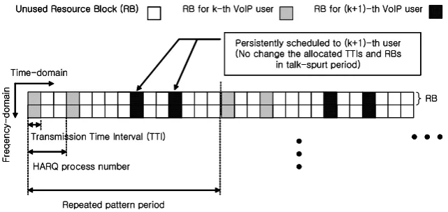
Figure 1: Resource assignment scenario according to the original persistent scheduling.
increase the capacity of VoIP in E-UTRA uplink. The proposed scheme modified the persistent scheduling al-gorithm such that the resources of two VoIP users can be coupled. By letting this coupled resources adap-tively shared by the two VoIP users, the proposed scheme achieves a significant amount of early-termination gain without the need of additional control signals.
2
Scheduling for VoIP services in
E-UTRA uplink
This section deals with the question of what kind of re-source allocation scheme is suitablefor satisfying the re-quired QoS of various services having different transmis-sion characteristics. Those services can be voice, stream-ing, web-browsing and file transfer, etc.
2.1
Conventional dynamic scheduling
Basically, dynamic resource allocation has been chosen for integrated scheduler of E-UTRA uplink transmission scheme. The integrated scheduler includes packet sched-uler, adaptive modulation and coding (AMC) unit, hy-brid automatic repeat request (HARQ) manager, power management unit and buffers [8]. They are all located at eNB to support fast channel-dependent scheduling. The packet dynamic scheduler is the main and the repre-sentative part of such integrated scheduler to select users for the assignment of time/frequency resources at every TTI. Resource block (RB), which consists of 12 subcar-riers, is the minimum scheduling granule of such packet scheduler in frequency-domain. With the unit of RB, in E-UTRA uplink, control parameters such as payload sizes and modulation coding sets (MCS) are determined by the eNB’s packet dynamic scheduler, depending on queue states in the user’s data buffer. Therefore, The reporting of the buffer status to eNB is essential. This allows for all the tight QoS control taken by the eNB and no QoS handling done at user-site.
The algorithm of packet scheduling can be divided into two parts, saying the selection of users and the
assign-ment of RBs. In the users selection procedure, dynamic scheduler chooses a particular user according to his/her priority that is calculated based on the PF algorithm. As for the RBs assignment, As for the RBs assignment, the scheduler exploits the benefit of multi-user frequency diversity. To do so, the RBs assignment for selected re-transmission is done by picking-up relatively good qual-ity of channels for the previous TTI. However, once RBs were allocated to a user, the retransmission packets of HARQ uplink should be maintained until the packets are correctly received or the maximum allowable time inter-val. This is because the E-UTRA system employed syn-chronous HARQ and non-adaptive AMC scheme for up-link to reduce the amount of control signals. Due to this limitation, it becomes less flexible to assign good RBs for the retransmission of uplink data, but HARQ combining gain still can benefit the retransmission quality.
However, downlink control channel signaling is classified into two groups to support uplink services. The first group is used to indicate the assigned RB’s information. It contains some user specific signals such as user iden-tification (UEID), cyclic redundancy check (CRC), RB assigned frequency-domain location, assignment time-domain duration, modulation, coding, payload size, etc [2]. Also, this control channel signaling is required at the beginning of each first transmission TTI because of the synchronous HARQ in E-UTRA uplink. The second is used to assign RBs in order to apply ACK/NACK infor-mation for uplink data.
2.2
Original persistent scheduling
"$ & ()) + ,
-. ))/0 )( 1+/ 21 3 3 +
5
1 // ( 6) - ) ( , ( 13 9 : +) ) + ( - / (2 5 - 9
) )) 6 ;/
5
69
- = ?@A3 +)
2 1 3 3 +
- = B CD 3 +)
21 3 3 +
F ((+ ; B H
1 )1 - I) +1 0 (13 (( 3 1 ; )+) = 3 +) )
"$ & ()) + ,
-. ))/0 )( 1+/ 21 3 3 +
5
1 // ( 6) - ) ( , ( 13 9 : +) ) + ( - / (2 5 - 9
: +) ) + ( - / (2 5 - 9
) )) 6 ;/
5
69
- = ?@A3 +)
2 1 3 3 +
- = B CD 3 +)
21 3 3 +
F ((+ ; B H
[image:3.595.131.451.93.228.2]1 )1 - I) +1 0 (13 (( 3 1 ; )+) = 3 +) )
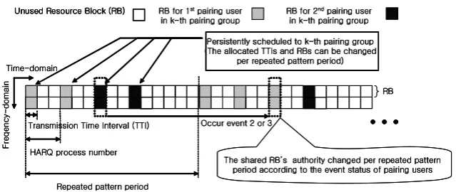
Figure 2: Resource assignment scenario with a resource sharing through user pairing.
(L1/L2) control channels.
By definition, the persistent assignment means that the resources are assigned by the eNB’s persistent grant for a relatively long period of time, i.e. talk-spurt period. Once an allocation, which does not change regardless of channel quality and queue status except when entering silent period. It is not required to inform the scheduling L1/L2 control channel signals except for the first estab-lishing time [5], [6]. So it is very efficient for the control signaling overhead reduction. The eNB’s scheduler can simply use the predefined persistent RBs in the allocated every TTI. The assigned resources are released only when the VoIP user at the talk-spurt state enters to the silent state. During the silent period, the silent payloads are transmitted by using the conventional dynamic schedul-ing method. This is because the L1/L2 control channel signaling overheads are not burden since the period of the silent frame is more than talk-spurt frame, i.e. 160msec. An example for the resource assignment scenario accord-ing to the original persistent schedulaccord-ing is illustrated in fig.1. As you can see the figure, the frequency-domain po-sition and the transmission TTIs of the assigned resources are statically configured. And these configurations are re-peated in every rere-peated pattern period. However, these persistent assignment are once coming on when a voice radio bearer is established, and then the configurations are not changed until the state transition. therefore, the L1/L2 control channel signals are almost not needed in the persistent scheduling scheme.
Although the persistent scheduling is very efficient to reduce the overheads of L1/L2 control channel signals, it is very inefficient to achieve some dynamic schedul-ing benefits such as early-termination gain and channel dependent scheduling. The early-termination gain means that the allocated resources, which is assigned to a sched-uled user, can be potentially available to other user when it is not used by the allocated user. It may be effi-cient in resource utilization. But, in the original persis-tent scheduling scheme, the allocated resources are not changed during the talk-spurt period. In other words, since the original persistent scheduling does not provide the early-termination gain, the available capacity of VoIP
is limited. Therefore, there is need a solution to improve the available VoIP capacity.
2.3
A proposed scheduling scheme
2.3.1 Concept of the proposed scheduling
In this section, an adaptive resource sharing scheme us-ing user pairus-ing, which can maintain the properties of the original persistent scheduling method, is proposed. De-sign objective of the proposed scheme is to achieve the early-termination gain by using user pairing of two VoIP users.
Table 1: Event status for indicating the authority of a shared RB
1st paired users’ 2nd paired users’ status ACK/NACK ACK/NACK
1 ACK ACK Maintain
2 ACK NACK Change
3 NACK ACK Change
4 NACK NACK Maintain
authority change when the 1 or 4 event status occurs. In order to perform the above process, one paired VoIP user in each pairing group only monitors the other paired user’s ACK/NACK channel information. So, there is no burden for control channel signaling to change the transmitting authority adaptively. However, the rest resources, excepting for the shared resources for pair-ing groups, are used accordpair-ing to the original persistent scheduling rule. Moreover, if left only one user in a pair-ing group because the other paired user’s assigned re-sources is released, the remaining user can be operated according to the original persistent configurations.
2.3.2 User pairing method
The resource sharing algorithm that we propose for VoIP services in E-UTRA uplink is designed to obtain the early-termination gain. It can be achieved by employing the user pairing. The user pairing can be classified as two methods basically. One is a random pairing that two sup-ported VoIP users can be paired as a pairing group with-out any consideration. It does not take into account the individual user radio channel condition, the data buffer status and the packet transmission delay in making a paired group. The other is a best pairing scheme which pairs two VoIP users to a paired group considering the individual status of user conditions. In this scheme, the best pairing chooses one user under good conditions and the rest under bad status of conditions in making a paired group. In other words, the delay sensitive user, who re-quires more retransmission opportunities due to a bad channel conditions, is favored by pairing a group with the delay non-sensitive users under a good channel condition. This pairing configuration can increase the number of 2 or 3 event occurrence. So, the discarded packets, which occur because of a timeout of the delay sensitive user, can be reduced by using the shared resources of the de-lay non-sensitive user. Therefore, best pairing can give a large efficiency to the proposed resource sharing schedul-ing scheme. However, in this paper the above two pairschedul-ing methods are compared to each other.
2.3.3 Description of overall operation for a
pro-posed scheduling scheme
In this section we describe the overall procedure of the proposed resource sharing scheduling scheme. The au-thority adaptation is executed every repeated pattern pe-riod. And, the user pairing can be also adjusted several times of repeated pattern periods. The overall procedure can be described on the eNB-site and user-site, which is summarized as follow:
The flow on the eNB-site:
- Pair two users according to the user pairing method.
- Assign RBs to each pairing group persistently using the measured priority that can be calculated by the modified PF in [4].
- Scheduler monitors the event status of the paired users in each pairing group.
- Change the transmission authority of shared RBs when meet the boundary of repeated pattern period and occur 2 or 3 event.
The flow on the user-site:
- Monitor his own ACK/NACK channel as well as the ACK/NACK channel allocated to the rest user in a pairing group.
- Change the available transmission RBs when meet the boundary of repeated pattern period and occur 2 or 3 event.
- Transmit VoIP packet using the allocated RBs when his assigned time.
2.3.4 Discussion on the control channel signaling
overhead
ui ui ui ui MME /SAE Gateway
Fixed (150ms) LTE Provider’s
IP Network
|l |l |l |l
T pwGG T n G
T iG T ui G
[image:5.595.65.259.93.266.2]T ksV|sGG T ksGG
|sGG |sGG |sGG |sGG GO\WP GO\WP GO\WP GO\WP
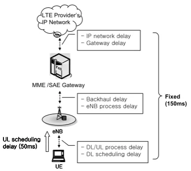
Figure 3: End-to-end delay components in E-UTRA.
3
VoIP services over E-UTRA uplink
3.1
The properties of VoIP services
3.1.1 Traffic model and protocol
In this paper the conversation traffic can be approximated to the two state Markov model with a suitable voice ac-tivity factor (VAF) [9]. The adaptive multirate (AMR) voice codec is mandatory for voice services in E-UTRA systems. The VoIP application generates 32-bytes voice payloads at 20ms intervals when conversation periods. 7-bytes payloads carries a silence descriptor (SID) frame at 160ms intervals when silent periods [10]. Also, we can set by 50% VAF.
A typical VoIP protocol stack, which employs the real-time transport protocol (RTP), is encapsulated to the user datagram protocol (UDP). This, in turn, is carried by IP. The combined these protocols demand a 40-bytes IPv4 header or a 60-bytes IPv6 header. Obviously, the overheads caused from the header to support VoIP ser-vices seriously degrade the spectral efficiency. Therefore, efficient and robust header compression (ROHC) tech-nique must be used to reduce the effects of relatively large headers in the IP/UDP/RTP layers. ROHC can reduce the size of the IP/UDP/RTP headers as little as 2 or 4 bytes using IETF RFC 3059 [11], [12].
3.1.2 Definition of VoIP capacity
In packet-switch (PS) network, packets will be dropped due to packet error and packet delay exceeding the tar-get latency. Although some packet loss occurs, the voice quality is not affected if the amount of packet loss is less than outage threshold. At this point, the VoIP capacity is defined by the maximum number of VoIP users that can be supported without exceeding a given outage threshold. The outage criterion means that packet error rate (PER)
of VoIP user is kept within 2%. Moreover, at least 95% of total VoIP users should meet the above outage criteria [11].
3.1.3 End-to-end delay latency for QoS support
To ensure end-to-end QoS, the low delay is one of the most important factor for maintaining high-quality VoIP services. But, to achieve high VoIP capacity, the sched-uler must have sufficient time to manage voice packets. Of the assumed 200ms end-to-end delay latency for qual-ified voice services, about 50ms is available for scheduling in the uplink [11]. The delay in others such as processing time for downlink/uplink, scheduling time for downlink, IP and backhaul network delay is bounded to 150ms. It is the fixed value allowing us to focus on the delay within radio access network as shown in fig. 3. Although VoIP performance depends on both downlink and uplink per-formance, we would like to set aside the consideration of both directions as comprehensive study for future re-search.
3.2
System-level simulation setup
3.2.1 Physical layer in E-UTRA uplink
For uplink transmission, the important property is to al-low user equipment (UE) for power efficient transmis-sion to maximize coverage. The choice of single-carrier frequency-domain multiple access (SC-FDMA) is thefore preferable in E-UTRA uplink. This is because the re-sulting peak-to-average power ratio (PAPR) is lower than orthogonal frequency division multiple access (OFDMA) in downlink. Also, the fast fourier transform (FFT) and inverse fast fourier transform (IFFT) are used in trans-mitter to produce the FDMA signal. So, multipath prop-agations are handled by frequency domain equalization at the eNB, aided by the insertion of a cyclic prefix (CP) in the transmitted signal. A subcarrier spacing of 15kHz is adopted, which allows for simple implementation of dual mode between wideband code division multiple ac-cess (WCDMA) and E-UTRA terminal. And the number of individual subcarrier as 12 consists of 1 RB. The RB is the basic time-frequency transmission resource unit in E-UTRA system. To minimize delays, the subframe du-ration (TTI) is selected as short as 1ms, corresponding to 14 OFDM symbols [2].
3.2.2 Simulation environments
To investigate the capacity performance of the VoIP traf-fic, a system-level Monte-Carlo computer simulation is accomplished in this paper. In all simulation, 5MHz sys-tem bandwidth is considered among the flexible band-widths. The simulations are carried out with a regular hexagonal 19 cellular model, where the inter-site distance (ISD) between eNB is 500m. Mobile terminals should be uniformly distributed on the 19-cell layout for each sim-ulation run and assigned by typical urban (TU) channel model according to the channel assignment probability specified in [2]. Note that a realistic model of the wave propagation plays an important role for the significance of the simulation results. Mobile speed is 3km/h since 3GPP E-UTRA system should be optimized for low mo-bile speed. Shadowing is modeled by a log-normal fading of the total received power. A basic attenuation is deter-mined by the Hata model.
Moreover, we consider the resources for control and com-mon channel overheads such as demodulation (DM) ref-erence signal (RS) and uplink ACK/NACK chancel for downlink transmitted data [13]. The synchronous HARQ modules with 8 process numbers are employed in this paper. Also, slow power control for uplink is employed bellowing as 200Hz. The applied MCS level is fixed as QPSK and 0.55 coding rate for VoIP services. Finally, it has to be mentioned that we simulate 40,000 TTI snap-shots (40seconds) in average for investigating the perfor-mance of the system. The main simulation parameters are summarized in Tables 2.
4
VoIP capacity evaluation
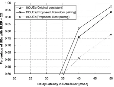
In this section we evaluate the capacity of VoIP traffic with employing the proposed scheduling scheme in the TU fading channel environments. The proposed scheme is also compared with the original persistent method. The percentage of VoIP users satisfying outage limita-tion, e.g. 2% PER, is presented in Fig. 4. It is shown as a function of the delay latency available to scheduler for different number of user. From the figure, we observe that the percentage of users satisfying outage criterion increases according to the increase of the available de-lay latency in scheduler. This is because the probability of packet loss because of a timeout of target delay la-tency becomes more decrease with higher delay lala-tency in scheduler. In addition, a proposed scheme results in the smaller required delay latency in scheduler to achieve the same outage performance than the corresponding original persistent scheduling scheme. For example, If we aim for an identical percentage value of 0.8 and the same number of user as 190, the required delay latency using a pro-posed scheme is 43msec when employing a random user pairing and 39msec when employing a best user pairing respectively. On the other hand, when using an origi-nal persistent scheme the required latency may be 52ms.
Table 2: System level simulation parameters
Parameter Assumption Source traffic AMR 12.2kbps,
packet overhead VAF=0.32, 2-state Markov, ROHC 4 bytes [IETF RFC 3059] Cellular layout Hexagonal grid, 19 sites, 3 sect.
(eNB-to-eNB 0.5km) Carrier frequency 2GHz System bandwidth 5MHz
Propagation loss Path loss=-128.1-37.6*log(R) Shadowing model Log Normal Std. dev. 8dB,
[Hata model] User speed 3km/h
Antenna gain Node B 14dB/UE 0dB Penetration loss -20dB
User Tx. 24dBm Max. Power
Fading model Typical urban(TU) Thermal noise -174dBm/Hz density
Number Rx ant. 2
Retransmission No RLC retransmission, sync. HARQ (max. retrial=4), HARQ process number=8, chase-combining
Power 50Hz(sounding RS based control closed-loop method) Scheduling Persistent scheduling
with a resource sharing using user pairing,
(repeated pattern period=20ms) MCS level QPSK, 0.55 coding rate,
talk-spurt period (2RBs assign); silent period (1RBs assign) Link curve Effective SIR method(ESM) mapping
Link curve TTI 1ms
Considered 29%(pilot and control overheads) overheads 2long blocks for DM RS
4RBs for control signals
This implies that the VoIP capacity can be increased if the proposed scheduling scheme is employed. Specifically, the more capacity benefits can be obtained by employing a best user pairing approach.
Fig. 5 characterizes the achievable VoIP capacity, when the delay latency in scheduler is 50msec statically. Ac-cording to the figure, we note that the available VoIP capacity with a proposed scheme employing a best user pairing is 200 against that the 168 VoIP users can be ser-viced by using original persistent scheduling.
re-0.50 0.55 0.60 0.65 0.70 0.75 0.80 0.85 0.90 0.95 1.00
20 25 30 35 40 45 50
Delay Latency in Scheduler [msec]
P
e
rc
e
n
ta
ge
of
U
E
s
w
it
h
B
LE
R
<
2
%
190UEs(Original persistent) 190UEs(Proposed, Ramdom pairing) 190UEs(Proposed, Best pairing)
Figure 4: Outage probability versus delay latency in scheduler for different number of VoIP user.
sults confirm that the VoIP capacity with a proposed scheme can be improved of 10% when using the random user pairing and 20% when using the best user pair-ing approach against the original persistent schedulpair-ing. Moreover, the available VoIP capacity employing a best user pairing scheme over E-UTRA uplink provides sig-nificantly highly capacity, e.g. 160%, if compare to the VoIP capacity over HSUPA (Release6).
5
Conclusion
In this paper, we propose the efficient scheduling method employing a resource sharing approach. This proposed scheme employs the random user pairing and the best user pairing method to improve the capacity of VoIP services over E-UTRA uplink. Results are investigated by the system-level simulation. Our simulation results show that the employment of proposed scheduling scheme makes a larger available capacity than that resulted by the original persistent scheduling. In addition, we also conclude that E-UTRA is attractive for supporting of VoIP services if compared to HSUPA (Release’6). The consideration of the combination of other traffic types such as best-effort, web and streaming may be an interesting issue for future study.
References
[1] 3GPP TR 25.913, Requirements for Evolved UTRA (E-UTRA) and Evolved UTRAN (E-UTRAN). [2] 3GPP TR 25.814, Physical layer aspect for evolved
UTRA.
[3] A. Jalali, R. Padovani and R. Pankaj, ”Data through-put of CDMA-HDR a high efficiency-high data rate personal communication wireless system,”IEEE Proc. VTC2000, pp.1854-1858, 2000.
[4] Y. -S. Kim, ”Capacity of VoIP over HSDPA with Frame Bundling,” IEICE Trans. Communications, vol.E89-B, no.12, pp.3450-3453, Dec. 2006.
0.50 0.55 0.60 0.65 0.70 0.75 0.80 0.85 0.90 0.95 1.00
100 110 120 130 140 150 160 170 180 190 200
Number of users
P
e
rc
e
n
ta
ge
of
U
E
s
w
it
h
B
L
E
R
<
2
%
Original persistent Proposed, Random pairing Proposed, Best pairing
Available VoIP capacity
Figure 5: Outage probability versus number of VoIP users.
Table 3: Summary of VoIP capacity using proposed scheduling scheme
Capacity IoT [dB] Original persistent scheme 168 3 Proposed (Random pairing) 188 3.2 Proposed (Best pairing) 200 3.3 HSUPA (Release’6) 70 3
[5] 3GPP R2-061920,Persistent Scheduling.
[6] 3GPP R2-062788,Persistent scheduling and dynamic allocation.
[7] T. Chen, M. Kuusela and E. Malkamaki, ”Uplink Ca-pacity of VoIP on HSUPA,” IEEE Proc. VTC2006-spring, pp.451-455, 2006
[8] Y. H. Kim and Y.-S. Kim, ”A Scheduler for Multi-Traffic Services in WCDMA Networks,”IEEE Proc. ISCIT2006, pp.1004-1007, 2006
[9] 3GPP TR25.896,Feasibility Study for Enhanced Up-link for UTRA FDD.
[10] 3GPP TS 26.236, Packet switched conversational multimedia application; Transport protocols.
[11] 3GPP R1-070674, LTE Physical layer frame work for performance verification.
[12] IETF RFC 3059, Attribute List Extension for the Service Location Protocol, February 2001.
[image:7.595.68.257.95.239.2] [image:7.595.323.513.97.239.2]