©IJRASET: All Rights are Reserved
256
Comparative Study of Frequency Control Method
of MGP System using Convectional PI and Fuzzy
Logic Controller
Dr. J. Vijaya Kumar1, D. Vasavi2 1
Associate Proffesor, 1, 2Department of Electrical Engineering, Anil Neerukonda Institute of Technology and Sciences (Autonomous), Visakhapatnam
Abstract: The paper here states, the comparative study of frequency control of MGP system with convectional PI and fuzzy logic controller is done. The electrical power generation has done by non renewable energy sources in most parts of the world. The carbon emissions during the production of electricity challenge the environmental issues which lead to pollution. So, there is a necessity for the interconnection of renewable energy sources with grid for the reduction in usage of non renewable energy sources. But, interfacing of renewable sources to the grid is not an easy task. The reduction of inertia in the power system, the frequency instability problems may limit the usage of renewable sources in the interfacing with the grid. The motor generator pair can deal with all the above problems very effectively. The source grid characteristics are analyzed by simulation using convectional PI controller and fuzzy logic controller. The fuzzy logic PI controller gives better results when compared with convectional PI controller. The results were compared by simulation whether the fuzzy PI controller gives best results or convectional PI controller.
Keywords: Frequency converter, sine pulse width modulation, motor generator pair, convectional PI controller, fuzzy logic PI controller.
I. INTRODUCTION
The transmission of the electric power is done mainly by the non renewable energy sources. This production of the electric power causes carbon emissions results in the environmental pollution. The interconnection of the power grid with renewable sources reduces this environmental pollution. The interconnection of the renewable energy sources to the power grid gives rise to instability problems in power system.
The renewable sources like wind, solar and other sources have random fluctuations and the power load will not be constant at all times. Research has been developing in this area to avoid the instability problems in power system with interconnection of renewable sources to grid. The power system does not run stably due to source load fluctuations and can be solved by high power penetration. At a particular point of time, a wind farm or a photo voltaic cell power generation is not constant but the all day generation is constant. The problems of interconnection with renewable sources with grid are
A. Inertia will be greatly reduced ad frequency stability problems arise due to the usage of the power electronic equipment. B. The faults caused in the power system directly affect the renewable sources that are connected to the grid.
C. When renewable energy sources are located in barren lands then the power export is difficult to the grid as it as weak support terminal.
In order to solve the above problems, Motor Generator pair is proposed. The renewable sources are not directly interconnected with the grid. The renewable sources are connected to the synchronous machines and these are connected to the power grid.
Before the introduction of MGP virtual synchronous generator (VSG) is used. But, the MGP system is better than VSG as there will be increase in the penetration energy. To provide the required inertia to the system VSG needs a large scale storage system for the energy for which more space is required. MGP can compensate for reactive power without any other usage of the compensated equipment. Moreover, for a MGP system there is no requirement of expensive battery storage systems for providing the required inertia to the system.
©IJRASET: All Rights are Reserved
257
II. THEPROPOSEDMOTORGENERATORPAIRMODEL
A. Mathematical Model
The motor generator pair (MGP) are designed by synchronous machines. The grid capacity is considered to be in MW scale. The designed MGP system is now connected to renewable source and power grid for the configuration.
The electrical model of the MGP system can be determined by taking the individual unit of the synchronous machine. ua, ub, uc, uf : stator voltage(3 phases), field voltage
ia, ib, ic: stator current (3 phases), field winding current ikd , ikq: d-axis and q-axis damper winding current ifd : field current
ψa, ψb, ψc, ψf : stator winding flux(3 phases), field winding flux θ: rotor position
From the basic voltage equations and flux linkage equations, we get
When the mutual inductance is considered, then
By parks transformation method, we obtain
Where,
Now, the votage and flux equations of dq axis is given by
Here, u0=uDd=uQq=0
As the generator and motor are two forms of synchronous machine, the equivalent motor can be obtained by changing the current reference direction
©IJRASET: All Rights are Reserved
258
When the torque acting on the rotor is unbalanced then, the unbalanced torqueThe rotor speed changes the unbalanced torque equation. The equation of rotor motion
When we use inertia time constant
The motor power angle can be expressed as
By solving the above equations, we get
Mechanical Model of Motor Generator Pair System
Where,
Δθ = phase adjustment amount = phase of power grid voltage
ѡ = angular frequency of power grid voltage
= frequency reference value of the frequency converter output voltage = output active power reference value of MGP system
= generator terminal voltage = generator output current
P = output active power of MGP system
, = inertia time constants
, = rotor angles
, = electromagnetic torque
, = damping coefficients
The active power transmitted by synchronous motor can be simplified to
=− sin
The active power transmitted by synchronous generator can be simplified to
=− sin
The power and the rotor angles of the synchronous machine are determined for the MGP systemby the above equation analysis.
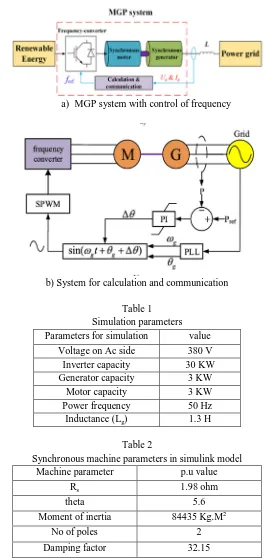
B. Control method by Convectional PI Controller
©IJRASET: All Rights are Reserved
259
a) MGP system with control of frequency [image:4.612.169.434.72.630.2]b) System for calculation and communication
Table 1 Simulation parameters Parameters for simulation value
Voltage on Ac side 380 V
Inverter capacity 30 KW
Generator capacity 3 KW
Motor capacity 3 KW
Power frequency 50 Hz
Inductance (Lg) 1.3 H
Table 2
Synchronous machine parameters in simulink model
Machine parameter p.u value
Rs 1.98 ohm
theta 5.6
Moment of inertia 84435 Kg.M2
No of poles 2
Damping factor 32.15
The values of PI controller are determined by the trial and error method. The values are KP =0.14, KI = 0.01.
©IJRASET: All Rights are Reserved
260
C. Fuzzy Logic ControllerThe recent technique in control applications used now a day is fuzzy logic. The use of fuzzy logic controller has growing and became prominence in many control system applications. The following illustrates the examples of the fuzzy control usage like regulating temperature in air conditioners, controlling of traffic lights etc..,
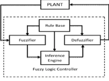
The different components of the Fuzzy Logic Controller are shown in below figure. 1) Fuzzifier: The main function of fuzzifier is to convert crisp values to fuzzy values.
2) Fuzzy Knowledge Base: The fuzzy input output relations storage is done here. The membership functions which define input variables and output variables are present here.
3) Fuzzy Rule Base: The knowledge based on the domain operation is stored here.
4) Inference Engine: By appropriate reasoning it simulates the human results and thus it is an essential part of the fuzzy logic controller
5) Defuzzifier: The main function of defuzzifier is to convert the fuzzy values to crisp values based on the output from the inference engine.
D. The Proposed FGPI Controller
[image:5.612.211.398.253.392.2]The real life data is converted into linguistic values by the fuzzy controller. Analysis is done according to user defined variations by membership functions during fuzzification for a fuzzy variable. The input always be the set of crisp values. The membership functions help in taking the inputs according to the output values. By the linguistic set qualification to degree of correspondence membership, the fuzzification process of the output starts. The two inputs that are taken by the fuzzy controller are control area error and change in control area error. There are 7 membership functions which convert the inputs into fuzzy in the fuzzifier. The membership functions are negative large (NL), negative medium (NM), negative small (NS), zero (Z), positive small (PS), positive medium (PM), positive large (PL). The input variables ranges from -0.25 to 0.25. The output variables ranges from 0 to 0.002 Rule base and inference engine is second part of the fuzzy logic controller. Decision making logic is given by rule base. For input membership functions we get the output values in terms of membership functions by various combinations. Here we have e (k) and ce (k) as the linguistic input and delPc as the linguistic output. The controller here is designed with 7 membership functions which has 49 rules. The table below illustrates the rules for the design of fuzzy logic controller. For the area control error e (k) and change in error ce (k) the rules are interpreted as if e(k) is NB and ce(k) is NS then delPc is S. Triangular membership functions are used for the input and output variables.
Table 3
Proportional and integral gains of the proposed FGPI controllers rules
E de
NB NM NS Z PS PM PB
NB PB PB PB PM PM PS Z
NM PB PM PM PM PS Z NS
NS PB PM PS PS Z NS NM
Z PM PM PS Z NS NM NM
PS PM PS Z NS NS NM NB
PM PS Z NS NM NM NM NB
©IJRASET: All Rights are Reserved
261
E. Membership functions1) Error
2) Change in Error
3) Output
©IJRASET: All Rights are Reserved
262
F. Simulation ResultsSimulation results for convectional PI controller of power angle, speed and power
©IJRASET: All Rights are Reserved
263
Active power by convectional PI controllerActive power by fuzzy logic controller
G. Comparison Of The Results Of The Above Three Systems
Convectional PI controller
Fuzzy with PI controller Over shoot
values (%)
0.65 0.6
Settling time (seconds)
1.4 sec 1.2 sec
III. CONCLUSIONS
The present paper is the analysis of the present energy usage and environmental issues. The penetration advantages and the problems in power system with the interconnection of renewable sources are also stated here. The usage of the MGP system for the reduction of frequency stability problems is proposed.
The mathematical model of the MGP system is analyzed and phase difference method is determined by the source grid phase difference and active power is been established. The source grid phase difference used to control the active power is very feasible by this MGP method.
©IJRASET: All Rights are Reserved
264
REFERENCES
[1] Z. Liu, Electric Power and Energy in China. Beijing, China: China Electric Power Press, 2012.
[2] X.Yang,Y. Song, G.Wang, andW.Wang, ``Acomprehensive reviewon the development of sustainable energy strategy and implementation in China,''IEEE Trans. Sustain. Energy, vol. 1, no. 2, pp. 57_65, Jul. 2010.
[3] G. Schellekens, A. Battaglini, J. Lilliestam, J. McDonell, and A. Patt, 100% Renewable Electricity_A Roadmap to 2050 for Europe and North Africa. London, U.K.: PriceWaterhouseCoopers, 2010.
[4] V. Indragandhi, V. Subramaniyaswamy, and R. Logesh, ``Resources, congurations, and soft computing techniques for power management andcontrol of PV/wind hybrid system,'' Renew. Sustain. Energy Rev., vol. 69,pp. 129_143, Mar. 2017.
[5] M. M. A. Rahman and A. T. Al Awami, ``Decentralized wind-PV-diesel based hybrid power generation,'' in Proc. Int. Conf. Elect. Eng. Inf. Commun. Technol. (ICEEICT), May 2015, pp. 1_5.
[6] V. Khare, S. Nema, and P. Baredar, ``Solar_wind hybrid renewable energysystem: A review,'' Renew. Sustain. Energy Rev., vol. 58, pp. 23_33, May 2016. [7] Z. Liu, Global Energy Internet. Beijing, China: China Electric Power Press, 2015
[8] Z. Liu, ``Global energy interconnection development and cooperation organization,'' Global Energy Interconnection Develop. Cooperation Org. (GEIDCO), Beijing, China, White Paper, 2017.
[9] M. Ashabani and Y. A.-R. I. Mohamed, ``Novel comprehensive control framework for incorporating VSCs to smart power grids using bidirectional synchronous-VSC,'' IEEE Trans. Power Syst., vol. 29, no. 2, pp. 943_957, Mar. 2014.
[10] H. Zhuang, H. Ju, and J. Xiao, ``Impacts of inverter interfaced distributed generations with high penetration level on power system transient and voltage stability,'' J. Electr. Power Sci. Technol., vol. 42, no. 17, pp. 84_89, 2014.
[11] T. Shintai, Y. Miura, and T. Ise, ``Oscillation damping of a distributed generator using a virtual synchronous generator,'' IEEE Trans. Power Del., vol. 29, no. 2, pp. 668_676, Apr. 2014.
[12] S. D'Arco and J. A. Suul, ``Virtual synchronous machines_Classi_cation of implementations and analysis of equivalence to droop controllers for microgrids,'' in Proc. IEEE Grenoble PowerTech (POWERTECH), Jun. 2013.
[13] K. Visscher and S. W. H. De Haan, ``Virtual synchronous machines (VSG's) for frequency stabilisation in future grids with a signi_cant share of decentralized generation,'' in Proc. CIRED Seminar, SmartGrids Distrib., Jun. 2008, pp. 1_4.
[14] H.-P. Beck and R. Hesse, ``Virtual synchronous machine,'' in Proc. 9th Int. Conf. Elect. Power Quality Utilisation, Oct. 2007, pp. 1_6.
[15] J. Alipoor, Y. Miura, and T. Ise, ``Power system stabilization using virtual synchronous generator with alternating moment of inertia,'' IEEE J. Emerg. Sel. Topics Power Electron., vol. 3, no. 2, pp. 451_458, Jun. 2015.
[16] Q.-C. Zhong and G. Weiss, ``Synchronverters: Inverters that mimic synchronous generators,'' IEEE Trans. Ind. Electron., vol. 58, no. 4, pp. 1259_1267, Apr. 2011.
[17] S. Wei, Y. Zhou, G. Xu, and Y. Huang, ``Motor-generator pair: A novel solution to provide inertia and damping for power system with high penetration of renewable energy,'' IET Generat. Transmiss. Distrib., vol. 11no. 7, pp. 1839_1847, 2017.
[18] S. Wei, Y. Zhou, S. Li, and Y. Huang, ``A possible con_guration with motor-generator pair for renewable energy integration,'' CSEE J. Power Energy Syst., vol. 3, no. 1, pp. 93_100, 2017.
[19] Y. Zhou, S. Wei, G. Xu, and Y. Huang, ``Research of the control method and operating pattern for the motor-generator Pair (MGP) grid-connected system,'' (in Chinese) Trans. China Electrotech. Soc., vol. 31, no. S2, pp. 159_166, 2016.