A Review on Work Piece Material in EDM
Processing Copper Electrode
Ghodke Shubham Maruti1, Kadam Aishwarya Ganesh2, 1
Student, Department of Mechanical Engineering, KLE Institute of Technology, Hubballi, Karnataka
2
Student, Department of Mechanical Engineering, Government Polytechnic Miraj, Miraj, Maharashtra
Abstract: Electro Discharge Machining (EDM) is a process used for machining very hard metals, deep and complex shapes by metal erosion in all types of electric conductive materials. In the present study the type of electrode used Copper. The metal is removed through the action of an electric discharge of short duration and high current density between the tool and the work piece. The eroded metal on the surface of both work piece and the tool is flushed away by the dielectric fluid. Present study mainly concentrates on copper electrode and output parameters such as metal removal rate, electrode wear rate and surface roughness. Metal removal rate, electrode wear rate and surface roughness have increased with increase in pulse on time. Higher pulse on time will produce higher material removal rate. For higher MRR the recommended parametric combination is pulse on time at level 1, pulse off time at level 2, voltage at level 2 and current at level 2. Surface roughness decreases with increasing pulse on time.
Keywords: Electro Discharge Machining (EDM), Material Removal Rate (MRR), Pulse Current and Copper electrode.
I. INTRODUCTION
Electrical discharge machining is considered as one of the main non-conventional machining processes used for manufacturing geometrically complex or hard material parts that are extremely difficult to machine by conventional machining processes. New developments in the field of material science have led to new engineering metallic materials, composite materials, and ceramics, having good mechanical properties and thermal characteristics as well as sufficient electrical conductivity so that they can readily be machined by spark erosion. Electrical discharge machine (EDM) technology is increasingly being used in tool, die and mould making industries, for machining of heat treated tool steels and advanced materials (super alloys, ceramics, and metal matrix composites) requiring high precision, complex shapes and high surface finish. Today, these alloys have a wide variety of applications in modern aerospace, marine, automobile sector, atomic power plant reactors, and medical implants owing to their high strength to weight ratios, high strength and toughness at elevated temperatures, excellent corrosion resistance, fracture resistance and low modulus of elasticity, good corrosion resistance in most environments. Researchers made attempts to model EDM process to study improvements in performance measures like material removal rate, surface roughness and tool wear rate.
IN THIS PROCESS, WORK PIECE SHOULD BE WELL ELECTRIC CONDUCTIVE.ONLY ELECTRIC CONDUCTIVE MATERIAL CAN BE MACHINED
BY THIS METHOD.THE WORKING OF EDM IS AS FOLLOW.
A. First both work piece and tool are submerged into dielectric fluid. The dielectric fluid help to control the arc discharge. This also removes suspended particles of work piece material and tool from the work cavity.
B. A servomechanism is used which maintains a very small gap between the work piece and the tool. This gap is desirable for proper arc formation. It is about the thickness of human hair.
C. The tool is made as the opposite shape of work piece.
D. A high frequency current supplied to electrode, which produces a spark between the tool and work piece. This spark generates high in work cavity.
E. The metal removed from the work piece due to erosion and evaporate ion.
F. The chips or suspended particle between tool and work piece should be removed to prevent them to form bridge that causes short circuit. This is done by continuous supply of dielectric fluid.
G. The EDM produce a cavity slightly larger than the electrode because of overcut.
II. EDMPARAMETERS
A. The different edm parameters are as follows. 1) Effect of pulse on time and pulse off time.
2) Effect of current on and current off
3) Effect on voltage
4) Effect on Material Removal Rate (MRR).
Electrical Discharge Machining mainly depends on work part material. Therefore a review is been done by choosing different work part material and the experimental results of the different researchers is been studied here. The electrode material used by all the researchers is copper.
The different work part materials reviewed are:
B.High Speed Steel (HSS).
1) Experimental Setup: Dr Arkanti Krishnaiah et.al. created A Minor model modern machine tools make electric discharge machine with a p-25 transistorized pulse generator having a maximum output of 85 V and 20 A was used to machine AISI T1 High Speed Steel specimens in this investigation. 50 X 12 X 12 mm AISI T1 High Speed Steel specimens were used. Copper electrode with diameter of 8.35 mm and Kerosene used as dielectric fluid with side flushing to carry out the experiments. A Sartorius CP 224S balance of capacity 220g and sensitivity of 0.1mg was used to measure the material removal rate based on the measurement of the respective weight loss due to machining of the specimens. A Mituttoyo surf tester SJ-301 was used to measure the roughness value; Ra in µm with sensitivity of 0.001µm for each specimen with a selected cut-off value of 0.25 mm and five sampling points have been taken. Roughness measurements were made on the specimens both in the direction of side flushing and normal to that direction. The chemical composition of the AISI T1 High Speed Steel
Figure 2. Ton vs. MRR (at I=10A & Toff=200µs)
Figure 3. Ton vs. MRR (at I=10A & Ton=200µs)
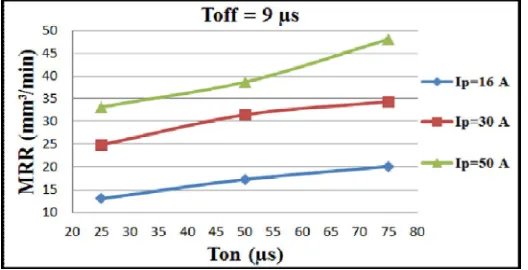
Figure 4. Pulse Current vs. MRR at different Ton
[image:3.612.179.443.427.562.2]same. Further, from the design of experiments (DOE), it is clear that pulse current, pulse on-time and their interaction has significant effect on the material removal rate
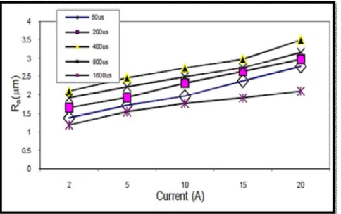
[image:4.612.184.441.210.377.2]3) Surface Roughness: The roughness of the electric discharge machined surface is associated with the distribution of the craters formed by the electric sparks. The experimental results reveals that for a constant pulse on-time, the surface roughness increases with increasing pulse current, as shown in Fig. 5. Further, it is noticed that for a constant current, the surface roughness decreases with increasing pulse on-time, as shown in Fig. 6. This phenomenon is similar to that observed in the case of the MRR. Therefore, it is possible to infer that a higher material removal rate will result in a rougher electric discharge machined surface. Further, it appears to be clear from the design expert plots also. Design expert response surface plot of pulse current and pulse on-time versus surface roughness has also confirmed the same.
Figure 5. Current (A) versus Surface Roughness
Figure 6. Pulse on-time (µs) versus Surface Roughness
C.Stainless Steel 304.
1) Experimental Setup: Rajmohan T et.al created work piece material used for the experiments was 304 Stainless steel. The Mechanical properties of 304 stainless steel are hardness value of the 304 Stainless steel was 35 HRc. The commercial EDM oil, spark erosion 450 (specific gravity 0.75, kinematic viscosity (at 40o) 23 CST and dielectric strength 12 KV min) was used as a dielectric fluid.
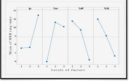
[image:4.612.186.428.417.569.2]the molten puddle and this results into ejection of more material out of the crater. Another observation from the present experiment is that the MRR increases with increase in pulse on time. The discharge energy in the plasma channel and the period of transferring this energy in to the electrodes increases with increase in pulse on time
Figure 7: Effect of process parameters on mean data of MRR
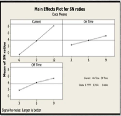
Figure 8: Effect of process parameters on S/N Ratios of MRR
This phenomenon leads to formation of bigger molten material crater on the work which results in increase in MRR However MRR decreases with increase in pulse off time. Since it is always desirable to maximize the MRR larger the better option is selected. Figure 2 suggested that when peak current is at 24A, pulse on time is at 150µs and pulse off time is at 35µs, provide maximum MRR. Optimum value of MRR is calculated as 14.88(mm³/min) and corresponding S/N ratio is 24.4453 at the optimal parameter settings.
[image:5.612.196.446.339.580.2]Figure 9. Current (A) versus Surface Roughness
D.Titanium Super Alloys.
1) Experimental Setup: J Laxman et.al. constructed an appropriate mathematical model to predict the value of MRR, EWR and SR. Experiments were carried out on die sinking EDM of type Asker microns, model V3525 with servo head constant gap voltage, positive polarity. Commercial 30 Grade EDM Oil was used as Dielectric fluid. The investigation was done on Titanium super alloys with Brinell hardness number 35 HB. The size of work pieces is 50mmX30mmX6mm and the diameter copper electrode is 12mm have been taken for the study. Preliminary experiments were conducted by varying the process input parameters for finding range of parameters. L27 orthogonal array was used to design the number of experiments. The results obtained were analysed and the models were produced using MINITAB Software. Tool material is of copper because of easy available in market and lower in cost.Wherever Times is specified, Times Roman or Times New Roman may be used. If neither is available on your wordprocessor,please use the font closest in appearance to Times. Avoid using bit-mapped fonts. True Type 1 or Open Type fonts are required. Please embed all fonts, in particular symbol fonts, as well, for math, etc.
2) Material Removal Rate: K Guru Raj et.al. Calculated the value of MRR and TWR, the work piece and tool are to be weighted, for this purpose they used SHIMADZU PHILLIPPINES, Digital sensitive weighting balance which is of 1mg accuracy. The work piece sample is weighted before machining and after machining and the MRR is obtained using the following equation. MRR = wp1 − wp2
T
Where wp1 and wp2 are the weights of the work piece before and after machining in mg/min Respectively, T is the machining time in minutes. Similarly TWR is calculated taking the weights of the tool before machining and after machining and is obtained by using following equation.
TWR = (wt1 − wt2)/ T
Where wt1 and wt2 are the weights of the tool electrode before and after machining in mg/min respectively. Pulse Current vs. MRR at different Ton is shown in fig. 10.
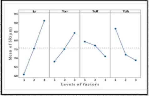
[image:6.612.201.426.568.710.2]3) Surface Roughness: The surface roughness of the work piece can be expressed in different ways including arithmetic average (Ra), average peak to valley height (Rz), or peak roughness (RP), etc. Generally, the SR is measured in terms of arithmetic mean, Ra which according to the ISO 4987: 1999 is defined as the arithmetic average roughness of the deviations of the roughness profile from the central line along the measurement in Fig. 11. Centre line average (CLA) is defined as the average values of the ordinates from the mean line, regardless of the arithmetic signs of the ordinates. Arithmetic mean or average surface roughness, Ra is considered in this study for assessment of roughness. The SR was measured on HANDYSURF. Three measurements of SR had been taken at different locations and the average values are taken for the analysis. The experiments are conducted according to L27 orthogonal array and the results.
Figure 11. Current (A) versus Surface Roughness
III. ADVANTAGES OF EDM
A. EDM can produce complex shapes that would otherwise be difficult to produce with conventional cutting tools.
B. EDM can cut extremely hard material to very close tolerances.
C. EDM can work on small work pieces where conventional cutting tools may damage the part from excess cutting tool pressure.
D. In EDM there is no direct contact between tool and work piece. Therefore delicate sections and weak materials can be machined without any distortion.
E. A good surface finish can be obtained.
F. Very fine holes can be easily drilled.
IV. DISADVANTAGES OF EDM A. Material Removal Rate in EDM machining is very less.
B. The additional time and cost used for creating electrodes for ram/sinker EDM.
C. Reproducing sharp corners on the work piece is difficult due to electrode wear.
D. Specific power consumption is very high.
E. Power consumption is high.
F. "Over cut" is formed.
V. APPLICATIONS A. It is used in the production of die for fabrication of all components.
B. EDM can be used in manufacturing of hydraulic valve spools, gear wheels, fine holes or slots in hard blade materials used in gas turbines, compressors, diesel engines etc.
C. It is used in fabrication, extrusion, and blanking, stamping and embossing dies.
D. It is also used for removal of drill and tapes from components.
E. EDM being a non-contact type of machining process, it is very well suited for making fragile parts which cannot take the stress of machining. The parts that fit such profiles include washing machine agitators.
F. Micro EDM process can successfully produce micro-pins, micro nozzle and micro-cavities.
H. Since there is no mechanical stress present (no physical contact), fragile and slender work places can be machined without distortion.
I. Delicate work piece like copper parts can be produced by EDM.
J. Hard and corrosion resistant surface, essentially needed for die making, can be developed.
VI. CONCLUSION A.From this Review we Can Conclude That
1) Higher pulse on time increases material removal rate.
2) With constant pulse on time the surface roughness increases with increases pulse current.
3) Surface roughness decreases with increasing pulse on time.
4) Higher MRR the recommended parametric combination is pulse on time at level 1, pulse of time at level 2, voltage at level 2 and current at level 2.
5) Increase in pulse off time causes MRR, TWR to decrease.
REFERENCES
[1] Siva Prasad Arikatla, Dr K.Tamil Mannan, Dr Arkanti Krishnaiah “Influence of Pulse Current and Pulse on Time on Material Removal Rate and Surface Roughness in Electric Discharge Machining of AISI T1 High Speed Steel” in Proc. of Int. Conf. on Emerging Trends in Engineering and Technology
[2] Rajmohan T, Prabhu R, Subha Rao G, Palanikumer k “Optimization of Machining Parameters in Electro Discharge Machining (EDM) of 304 Stainless Steel” in International conference on Modelling, Optimisation and Computering ICMOC 2012.