VLSI Design of a Novel Architecture for Data
Encoding with Golay codes
E.Odevi1, V. B. K. L. Aruna2
1
Studying M.Tech. in VLSI & ES specialization, Velagapudi Ramakrishna Siddhartha Engineering College, Jawaharlal Nehru Technological University -Kakinada, Kanuru, Vijayawada-7, Andhra Pradesh)
2
Assistant Professor, Electronics and Communication Engineering department, Velagapudi Ramakrishna Siddhartha Engineering College, Jawaharlal Nehru Technological University -Kakinada, Kanuru, Vijayawada-7, Andhra Pradesh)
Abstract:There is an expanding interest for productive and dependable transmission of computerized information. A noteworthy worry here is the control of blunders for dependable generation of information. By appropriate encoding of data to a codeword with the assistance of Error Correction Codes (ECC), errors induced can be reduced. The proposed architecture parallelizes the comparison of the data and that of the parity information. To further reduce the latency and complexity, in addition, a new butterfly-formed weight accumulator (BWA) is proposed for the proficient calculation of the Hamming separation. Grounded on the BWA, the proposed design analyzes whether the approaching information coordinates the put away information if a specific number of wrong bits are amended. . The proposed engineering is actualized by utilizing xilinx14.7 form and the trial comes about demonstrate that the proposed design lessens the dormancy and the equipment multifaceted nature separately. In expansion we do Golay code for more decrease in the idleness. Golay code is a different mistake adjusting parallel code equipped for remedying a blend of three or couple of arbitrary blunders in a piece of 23 digits.The Comparison of Golay Code and BWA is due to Delay and Speed.
Keywords: Data Comparison, Hamming distance, Systematics codes, Tag matching, Error correcting codes (ECCs), Encoder, CRC, Golay code.
I. INTRODUCTION
II. EXISTING SYSTEM
A. Decode-and-Compare Architecture
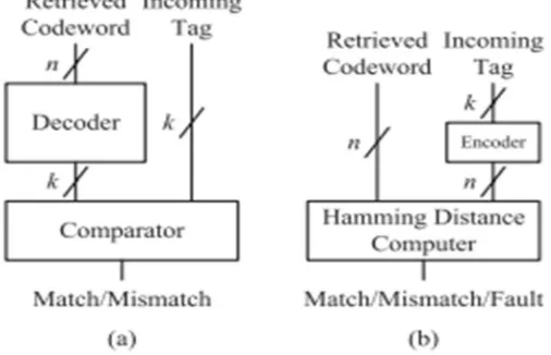
Give us a chance to consider a reserve memory where a k-bit tag is put away as a n-bit codeword subsequent to being encoded by a (n, k) code. In the unravel and-think about engineering delineated in Fig. 1(a), the n-bit recovered codeword should first be decoded to extricate the first k-bit tag. The extricated k-bit tag is then contrasted and the k-bit label field of an approaching location to decide if the labels are coordinated or not. As the recovered codeword ought to experience the decoder before being contrasted and the approaching tag, the basic way is too long to ever be utilized in a functional reserve framework intended for fast access. Since the decoder is a standout amongst the most entangled handling components, moreover, the multifaceted nature overhead isn't unimportant.
B. Encode-And-Compare Architecture
[image:2.612.183.436.397.560.2]Note that translating is typically more perplexing and takes additional time than encoding as it includes a progression of mistake location or disorder count, and blunder adjustment [7]. The execution brings about help the claim. To determine the disadvantages of the unravel and-think about engineering, along these lines, the deciphering of a recovered codeword is supplanted with the encoding of an approaching tag in the encode-and-look at design More correctly, a k-bit approaching tag is first encoded to the relating n-bit codeword X and contrasted and a n-bit recovered codeword Y as appeared in Fig. 1(b). The examination is to analyze what number of bits the two code words vary, not to check if the two code words are precisely equivalent to each other. For this, we figure the Hamming separation d between the two code words and order the cases as per the scope of d. Let tmax and rmax signify the quantities of maximally correctable and discernible blunders, separately. The cases are outlined as takes after.
If d = 0, X matches Y exactly.
If 0 < d ≤ tmax, X will match Y provided at most tmax errors in Y are corrected.
If tmax < d ≤ rmax, Y has detectable but uncorrectable errors. In this case, the cache may issue a system fault so as to make the central processing unit take a proper action.
Fig. 1.(a) Decode-and-compare architecture and (b) encode-and-compare architecture.
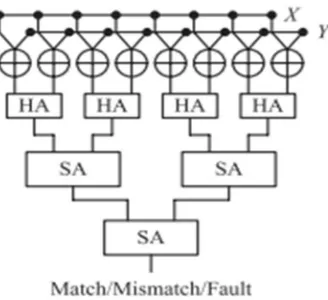
Since the above strategy needs to process the Hamming separation, exhibited a circuit devoted for the calculation. The circuit appeared in Fig. 2 initially performs XOR activities for each match of bits in X and Y in order to create a vector speaking to the bitwise contrast of the two code words. The accompanying half adders (HAs) are utilized to include the quantity of 1's two neighboring bits in the vector. The quantities of 1's are amassed by going through the accompanying SA tree. In the SA tree, the collected esteem z is soaked to rmax + 1 in the event that it surpasses rmax. All the more accurately, given data sources x and y, z can be communicated as takes after:
z = x + y, if x + y ≤ rmax
The final accumulated value indicates the range of d. As the compulsory saturation necessitates additional logic circuitry, the complexity of a SA is higher than the conventional adder
Fig. 2. SA-based architecture supporting the direct compare method.
III. BWA ARCHITECTURE
This section presents a new architecture that can reduce the latency and complexity of the data comparison by using the characteristics of systematic codes. In addition, a new processing element is presented to reduce the latency and complexity further.
A. Datapath Design for Systematic Codes
[image:3.612.233.397.108.258.2]In the SA-based architecture, the comparison of two code words is invoked after the incoming tag is encoded. Therefore, the critical path consists of a series of the encoding and the n-bit comparison as shown in Fig. 3(a). However, did not consider the fact that, in practice, the ECC codeword is of a systematic form in which the data and parity parts are completely separated as shown in Fig. 4. As the data part of a systematic codeword is exactly the same as the incoming tag field, it is immediately available for comparison while the parity part becomes available only after the encoding is completed. Grounded on this fact, the comparison of the k-bit tags can be started before the remaining (n–k)-bit comparison of the parity bits. In the proposed architecture, therefore, the encoding process to generate the parity bits from the incoming tag is performed in parallel with the tag comparison, reducing the overall latency as shown in Fig. 3(b).
Fig. 3. Timing diagram of the tag match in (a) direct compare method (b) proposed architecture.
[image:3.612.200.411.465.584.2]B. Architecture for Computing the Hamming Distance
[image:4.612.180.420.123.298.2]The proposed architecture grounded on the datapath design is shown in Fig. 5. It contains multiple butterfly-formed weight accumulators (BWAs) proposed to improve the latency and complexity of the Hamming distance computation.
Fig. 5. BWA architecture for systematic code words
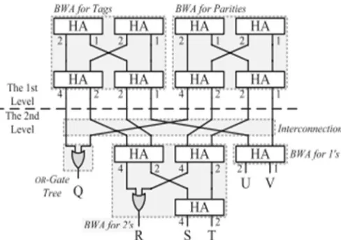
The basic limit of the BWA is to count the amount of 1's among its information bits. It contains different periods of HAs as showed up in Fig. 6(a), where each yield bit of a HA is connected with a weight. The HAs in a stage are related in a butterfly shape with a specific end goal to accumulate the pass on bits and the total bits of the upper stage freely. All things considered, the two commitments of a HA in a stage, except for the primary stage, are either pass on bits or whole bits figured in the upper stage. This affiliation methodology prompts a property that if a yield bit of a HA is set, the amount of 1's among the bits in the ways accomplishing the HA is proportional to the largeness of the yield bit. In Fig. 6(a), for example, if the pass on bit of the diminish shaded HA is set, the amount of 1's among the related data bits, i.e., A, B, C, and D, is 2. At the last period of Fig. 6(a), the amount of 1's among the data bits, d, can be found out as
d = 8I + 4 (J + K + M) + 2 (L + N + O) + P. (2)
The corresponding first and second level circuits are shown in Fig. 7. Note that the encoder and XOR banks are not drawn in Fig. 7 for the sake of simplicity. Since rmax = 2, Pmax = 2 and there are only two BWAs dealing with weights 2 and 1 at the second level. As the bits of weight 4 fall in the fourth range, they are ORed. The remaining bits associated with weight 2 or 1 are connected to their corresponding BWAs. Note that the interconnection induces no hardware complexity, since it can be achieved by a bunch of hard wiring.
[image:4.612.181.425.533.705.2]IV. EXTENSION
By proper encoding of information to a codeword with the help of Error Correction Codes (ECC), errors induced can be reduced [9] [10]. The (23, 12) Golay code is a multiple error correcting binary code capable of correcting an combination of three or few random errors in a block of 23 digits. For hardware implementation of encoding process, Linear Feedback Shift Register (LFSR) based cyclic redundancy check (CRC) generation method is preferred conventionally [11]. Due to drawbacks like high latency and less throughput, this technique is not a suitable solution for high-speed applications. Here, a technique based on CRC method, without using LFSR’s, proposed in [12] is considered for the encoding of golay code.Golay code with minimum distance of seven is the only known multiple error correcting binary perfect code. The binary Golay code is represented as (23, 12, 7) that depicts that length of codeword is 23 bits, while message is of 12 bits and the minimum distance between two binary Golay codes is 7.This code can be in cyclic form, hence it can be decoded or encoded using its cyclic structure. The generation of coding sequence needs a generator polynomial. The possible generator polynomials over GF (2) for Golay (23, 12, 7) code are
G(x) =x11 + x10 + x6 + x5 + x4 + x2 + x1 G(x) =x11+x9+x7+x6+x5+x1+1.
Encoding can be done by eleven stages Shift Register (SR) with feedback connections according to either of the above given G(x).
The remainder of the long division gives the required check bits. Finally, appending the generated check bits with the message gives us the Golay codeword.
Fig.8 Architecture for generation of binary golay code
A. G23 Golay Code Generation
V. RESULTS
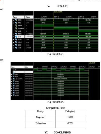
[image:6.612.86.487.59.589.2]A. Proposed
Fig. Simulation.
B. Extension
Fig. Simulation.
Comparison Table
Design Delay(ns)
Proposed 1.899
Extension 0.284
VI. CONCLUSION
REFERENCES
[1] J. Chang, M. Huang, J. Shoemaker, J. Benoit, S.-L. Chen, W. Chen, S. Chiu, R. Ganesan, G. Leong, V. Lukka, S. Rusu, and D. Srivastava, “The 65-nm 16-MB shared on-die L3 cache for the dual-core Intel xeon processor 7100 series,” IEEE J. Solid-State Circuits, vol. 42, no. 4, pp. 846–852, Apr. 2007.
[2] J. D. Warnock, Y.-H. Chan, S. M. Carey, H. Wen, P. J. Meaney, G. Gerwig, H. H. Smith, Y. H. Chan, J. Davis, P. Bunce, A. Pelella, D. Rodko, P. Patel, T. Strach, D. Malone, F. Malgioglio, J. Neves, D. L. Rude, and W. V. Huott “Circuit and physical design implementation of the microprocessor chip for the zEnterprise system,” IEEE J. Solid-State Circuits, vol. 47, no. 1, pp. 151–163, Jan. 2012
[3] H. Ando, Y. Yoshida, A. Inoue, I. Sugiyama, T. Asakawa, K. Morita, T. Muta, and T. Motokurumada, S. Okada, H. Yamashita, and Y. Satsukawa, “A 1.3 GHz fifth generation SPARC64 microprocessor,” in IEEE ISSCC. Dig. Tech. Papers, Feb. 2003, pp. 246–247.
[4] M. Tremblay and S. Chaudhry, “A third-generation 65nm 16-core 32-thread plus 32-scout-thread CMT SPARC processor,” in ISSCC. Dig. Tech. Papers, Feb. 2008, pp. 82–83.
[5] AMD Inc. (2010). Family 10h AMD Opteron Processor Product Data Sheet, Sunnyvale, CA, USA[Online].Available:
http://support.amd.com/us/Processor_TechDocs/40036.pdf
[6] Byeong Yong Kong, Jihyuck Jo, Hyewon Jeong, Mina Hwang, Soyoung Cha, Bongjin Kim, and In-Cheol Park, “Low-Complexity Low-Latency Architecture for Matching of Data Encoded with Hard Systematic Error-Correcting Codes”, IEEE Transactions on Very Large Scale Integration (VLSI) Systems, Vol. 22, No. 7, July 2014
[7] S. Lin and D. J. Costello, Error Control Coding: Fundamentals and Applications, 2nd ed. Englewood Cliffs, NJ, USA: Prentice-Hall, 2004
[8] W. Wu, D. Somasekhar, and S.-L. Lu, “Direct compare of information coded with error-correcting codes,” IEEE Trans. Very Large Scale Integr.(VLSI) Syst., vol. 20, no. 11, pp. 2147–2151, Nov. 2012.
[9] Sarangi, Satyabrata, and Swapna Banerjee. "Efficient Hardware Implementation of Encoder and Decoder for Golay Code." Very Large Scale Integration (VLSI) Systems, IEEE Transactions on 23.9 (2015): 1965-1968
[10] Su,Shin-Yuan, and Pai_Chi Li."Photoacoustic signal generation with Golay coded excitation." Ultrasonic Symposium (IUS), 2010IEEE. IEEE, 2010
[11] Nair, Rajesh, Gerry Ryan, and Farivar Farzaneh. "A symbol based algorithm for hardware implementation of cyclic redundancy check(CRC)."VHDL International Users' Forum, 1997. Proceedings. IEEE, 1997