Simulation of Fuel Cell by Moth Flame
Optimization and to Control the Parameters of
PI-Controller
Kiran Bala1, Navdeep Kaur Brar2 1
M.Tech Student 2Assistant Professor, Department of Electrical Engineering, Baba Banda Singh Bahadur Engineering College, Fatehgarh Sahib , Punjab
Abstract: Due to the increment in the demand of energy and power, variations in the price of oil and various environmental issues, the subject of renewable energy is becoming significant among research domain. Among all the available sources of energy, the fuel cell has been considered as the prominent one due to its various features such as cost effectiveness, higher efficiency and cleanliness. This study entitled the novel approach for enhancing the performance of fuel cell system. The model of present fuel cell is designed by using the PI controller, DC-DC Converter and MFO optimization mechanism. The role of the Moth Flame Optimization (MFO) technique is to optimize the parameters of the PI controller. The work is simulated on Simulink-MATLAB platform. The performance evaluation of the proposed work is one in the terms of voltage output, overshoot, settling time and rise time. On the basis of the obtained results it is proposed that the proposed model outperforms the traditional model.
Keywords: Fuel Cell, DC-DC Converter, Moth Flame Optimization, PI Controller.
I. INTRODUCTION
The popularity of Fuel cell technology is increasing because of the climate change and depletion of energy resources made from petroleum. Electrolyte employee fuel cell is an electrochemical device that converts chemical energy of fuels into electrical energy. it has an efficiency of 60% in converting electrical energy and a total of 80% in generating both thermal and electrical energy and reduces the pollutants up to 90%. Five fuel cells are majorly used to obtain the results of the research. These are phosphoric acid fuel cells, alkaline fuel cells, molten carbonate fuel cells, polymer electrolyte membrane fuel cells or PEMFCs. Platinum based material as catalyst and polymer electrolyte membrane as proton are used for construction of polymer electrolyte membrane fuel cells. The power density is high, operating temperature is low and it makes PEM fuel cells as power source of next generation for stationary as well as portable applications.
II. PROBLEM FORMULATION
Over the years, the conventional control such as the proportional-integral (PI) controllers have been used together with vector control methods to better control the parameters for fuel cell. Whereas in traditional work, the PI controller was used to do so. The PI controller utilizes the parameter such as Kp . These parameters selection is done on the basis of hit and trail method and when these parameters meet any variations in their values, the whole controller gets effected in such case. Thus in such cases the parameters for fuel cell can vary. Therefore there is a requirement to develop such a system that can handle the parameters for fuel cell in each and every case.
III. PROPOSED WORK
As defined in above section that in order to control the parameters of Fuel Cell, various authors conduct various study by using different type of controllers such as PI, PID controllers, arduino controllers. The PI controllers are evaluated as the most suitable controller to the Fuel Cell system as this is the less complex mechanism and did not include any of the mathematical models. The purpose of this study is to control the variations in parameters for fuel cell by enhancing the traditional technique by using the MFO (Moth Flame Optimization) optimization algorithm to select the parameters for PI controller. The key advantages are that it can provide very quick convergence at a very initial stage by switching from exploration to exploitation. This makes it an efficient algorithm for applications when a quick solution is needed. Techniques used in proposed work are MFO and PI controller. These techniques are explained briefly in this section.
A. MFO (Moth Flame Optimization)
⎣ ⎦
B. PI controller design ( , ) plane
The boundary for ( , , ) = 0 for the ( , ) Plane for a fixed value of = is as explained for = 0, the PID controller will reduce to the PI controller which is given in the frequency domain by
( ) = + … … … (3)
Where and are the proportional and integral gains of the PI controller Frequency domain of the PI controller for ( , , ) = 0 in the( , ) plane,
=
0
− … … … (4)
Solving equations (4) for all ω≠0 and θA€ 0, 2ᴫ, we get,
( , ,− ) =
− ( )−1( + )
( ) … … . (5)
( , ,− ) =
− ( ( ) +1( + )
( ) … . . (6)
X( ) = ( )( ) + | ( )| + ( )( − ) + ( )( + ) … … (7)
For = 0, equation (38) will give,
0 0
0 0 =
0
0 … … . (8)
From equation (41), the results are drawn that Kp(0,θA, ) KI(0, θA, ) = 0, Unless
(0) = (0) = 0 … … . . (9)
which is possible only when
→ ∞ and (0) = (0) = 0 Which is obtained only when ( ) has a zero at the origin.
IV. RESULTS
Figure 1: Proposed model for fuel cell system
[image:3.612.188.424.316.478.2]The graph in figure 2, represents the output voltage ( ) of proposed system. On the basis of the graph, it is observed that the initial the voltage is 0 but then suddenly it started falling below -5. After a period of time the voltage output rises to 0 again and then it remains constant till the end.
Figure 2: Output Voltage ( ) of Proposed System
The graph in figure 3, shows the fitness evaluation of proposed work. The x axis in the graph depicts the number of iteration and the y axis in the graph delineates the values for the fitness that ranges from 645 to 690. The number of iterations considered for proposed work is 50. The graph makes it clear that initially, the highest fitness value is observed i.e. 686 approx. then with the increment in the number of iteration the fitness values started falling and at the 50th iteration, the obtained best fitness value i.e. 646 approximately.
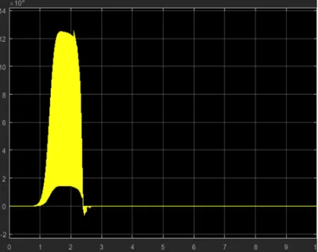
[image:3.612.207.410.564.715.2]Figure 4: Duty Cycle of proposed work.
[image:4.612.198.414.323.497.2]The proposed work is simulated in Simulink-Matlab by considering various values of current i.e. I1, I2, I3 and I4. The graph in figure 5 depicts the performance of the proposed work with respect to the I1.
Figure 5: Performance with respect to current I1
The graph in figure 6, figure 7 and figure 8 delineates the output for I2, I3 and I4. On the basis of the results shown in graphs it is concluded that the current generated by the proposed work comprises of less fluctuation.
[image:4.612.194.419.542.720.2]Figure 7 : Performance with respect to current I3
Figure 8: Performance with respect to current I4
The graph in figure 9 shows the error of proposed system. The error of proposed work is evaluated by measuring the difference between current I4 and current I1. The graph proves that the response of proposed system is reasonable.
Figure 9: Error of proposed work
[image:5.612.198.411.512.700.2]Figure 10 Voltage of Fuel Cell
[image:6.612.198.415.72.238.2]The facts and digits shown in table 1 define the comparison analysis of proposed and traditional work in the term of overshoot, settling time and rise time. On the basis of the shown statistics it is observed that the overshoot of proposed and traditional work is 0, the settling time for traditional work is 601.6474 and for proposed work it is 494.521, similarly, the rise time for traditional work is 131.4961 and for proposed work is 105.9986. Hence this is proved that the proposed work performs better than the traditional work in each and every term.
Table 1: Performance evaluation of proposed work
Parameters Traditional Model [2] Proposed Model
Overshoot 0 0
Settling Time 601.6474 494.521
Rise Time 131.4961 105.9986
V. CONCLUSION
Fuel cells are used as an alternative to the various energy resources such as oil, petroleum and diesel etc. Fuel cells can be defined as electrochemical cells that are utilized to generate the electrical energy out of chemical energy. These cells are prominent and popular as there is no need of human intervention to produce heat and it also leads to less pollution in comparison to other energy resources. This study develops an approach for enhancing the power and reducing the error in fuel cell system by using PI controller and MFO optimization mechanism. On the basis of the implemented results it is concluded that the proposed work leads to the reliable voltage output, 0(zero) overshoot, lesser settling time and rise time in the system. The outperformance of these performance parameters make it better than the traditional fuel cell systems.
In future more amendments could be done in present work by implementing the fuzzy based PID control to enhance the performance of the fuel cell.
REFERENCES
[1] Mohamed Derbeli, Maissa Farhat, Oscar Barambones, Lassaad Sbita, “Control of Proton Exchange Membrane Fuel Cell (PEMFC) Power System Using PI Controller”, IEEE Green Energy Conversion Systems (GECS), 2017 International Conference, pp. 1-5, 2017.
[2] Milton Rafael da Silva, “Modeling of a Fuel Cell with PI Controller in Simulink – Matlab”, The 2016 3rd International Conference on Systems and Informatics (ICSAI 2016), pp. 160-165, 2016.
[3] Ashitha P.N., J. S. Lather, “Fuzzy PI based power sharing controller for grid tied operation of a fuel cell”, 2016 IEEE Student’s Conference on Electrical, Electronics and Computer Science, pp. 1-6, 2016.
[4] N. A. Zambri, M. N. Ismail, Azah Mohamed, “Performance Comparison of PI and PI-Fuzzy Controller for Grid-Connected Fuel Cell Inverter System”, Innovative Smart Grid Technologies - Asia (ISGT ASIA), 2015 IEEE, pp. 1-6, 2015.
[5] Mohamed Derbeli, Maissa Farhat, Oscar Barambones, Lassaad Sbita, “A Robust MPP Tracker Based on Backstepping Algorithm for Proton Exchange Membrane Fuel Cell Power System”, Compatibility, Power Electronics and Power Engineering (CPE-POWERENG), 2017 11th IEEE International Conference, pp. 424-429, 2017.
[6] Yun Zhang, Chuanzhi Fu, Mark Sumner, Ping Wang, “A Wide Input-Voltage Range Quasi-Z Source Boost DC-DC Converter with High Voltage-Gain for Fuel Cell Vehicles”, IEEE TRANSACTIONS ON INDUSTRIAL ELECTRONICS, vol. 3, pp. 1-9, 2018.
[7] D. C. Das, Hareesh Sriramoju, Sudhanshu Ranjan, N. Sinha, “VOLTAGE CONTROL OF FUEL CELL-WIND-DIESEL HYBRID POWER SYSTEM USING FA BASED SVC AND AVR CONTROLLER”, 2017 IEEE Region 10 Humanitarian Technology Conference (R10-HTC), pp. 606-609, 2017. [8] Ahmed M. Kassem, S. A. Zaid, “Optimal Control of a Hybrid Renewable Wind/ Fuel Cell Energy in Micro Grid Application”, 2017 Nineteenth
International Middle East Power Systems Conference (MEPCON), pp. 84-90, 2017.
[10] Yun Wang , Ken S. Chen, Jeffrey Mishler, Sung Chan Cho, Xavier Cordobes Adroher, “A review of polymer electrolyte membrane fuel cells: Technology, applications, and needs on fundamental research”, ELSEVIER, Vol 88, pp 981-1007, 2011.
[11] T. Pavlović, , T. Bjažić, , Ž. Ban, “Modeling and current control of fuel cell-battery hybrid system with boost converter and input-output filters”, IPEMCC, pp 1-6, 2012.
[12] Mohamed A. El-Sayed , Adel M. Sharaf, “A novel stabilization dynamic filter scheme for Fuel Cell utilization system”, IEPEC, pp 1-8, 2009.
[13] A. K. Saha , S. Chowdhury , S. P. Chowdhury , Y. H. Song, “Software simulation of PEM fuel cell system for dynamic performance analysis”, IUPEC, pp 758-762, 2007.
[14] Ashish Tiwari , Omprakash Jaga , Shakti Singh Soni, “Sliding mode controller based quadratic boost converter for fuel cell system”, RDCAPE, pp 142-146, 2017.
[15] M. Padma Lalitha , T. Janardhan , R. Madhan Mohan, “Fuzzy logic based wind energy conversion system with Solid oxide fuel cell”, ICHPCA, pp 1-6, 2014.


![Table 1: Performance evaluation of proposed work Traditional Model [2]](https://thumb-us.123doks.com/thumbv2/123dok_us/1254197.652549/6.612.198.415.72.238/table-performance-evaluation-proposed-work-traditional-model.webp)
