Estimation and Costing Comparison with Manual
and Software (Excel)
Mohammed Furkhan1, Mushtaq Ahmed2, Najam Uddin3, Mir Mahmood Ali4, Hussain5
1
Geo-Tech Engineer, Lord Institute Of Engineering & Technology, Hyderabad, India 2, 3, 4, 5
(Civil Engg) Scholar of Lords Institute Of Engineering & Technology.
Abstract: An estimate is a computation of the quantities required and expenditure likely to be incurred the construction of a work. In any construction project, the probable cost of construction which is known beforehand is known as the estimated cost. And hence it is quite essential for the arrangement of financial resources for the completion of any construction project.
In this project, the main aim was to find out the detailed estimate of quantities of all the structural aspect of G+5 building. It is located at GULZAR HOUSE which is in HYDERABAD. It also aims in finding out the probable cost, or the estimated cost of the project based on the computation of these quantities. The structural aspects considered for the estimation of quantities are earthwork in excavation and backfilling, concrete work in foundation and in R.C.C structures such as beams, columns, slabs, staircases etc., steel reinforcement in beams, columns and other R.C.C structures and brickwork in superstructure. The computation of quantities was carried out based on the drawings of various structural elements, such as the each floor plan, footings and columns layout, beams layout, staircases layout, footing specifications and column specifications, which have also been provided in this document. These details provide an idea for requirement of quantities for a particular project and also the likely expenditure which would be needed to be arranged .This documentation also provides the abstract of the estimated cost for the structural aspects. From this project we have estimated the manual and the software calculations in which we got a cost difference in manual as well as in software from which the software(EXCEL) is approx calculation when compare to manual calculations. Hence we are showing the comparison of both software and the manual calculation from which we are getting a cost (price) difference of 30%.
I. INTRODUCTION
Estimation (or estimating) is the process of finding an estimate, or approximation which is a value that is usable for some purpose
even if input data may be incomplete, uncertain or unstable. The value is nonetheless usable because it is derived from the best information available. Typically, estimation involves "using the value of a statistic derived from a sample to estimate the value of a corresponding population parameter". The sample provides information that can be projected, through various formal or informal processes, to determine a range most likely to describe the missing information. An estimate that turns out to be incorrect will be an overestimate if the estimate exceeded the actual result, and an underestimate if the estimate fell short of the actual result.
A. How Estimation is Done
B. Uses Of Estimation
In mathematics, approximation describes the process of finding estimates in the form of upper or lower bounds for a quantity that cannot readily be evaluated precisely, and approximation theory deals with finding simpler functions that are close to some complicated function and that can provide useful estimates. In statistics, an estimator is the formal name for the rule by which an estimate is calculated from data, and estimation theory deals with finding estimates with good properties. This process is used in signal processing, for approximating an unobserved signal on the basis of an observed signal containing noise. For estimation of yet to be observed quantities, forecasting and prediction are applied. A Fermi problem, in physics, is one concerning estimation in problems which typically involve making justified guesses about quantities that seem impossible to compute given limited available information.
Estimation is important in business and economics, because too many variables exist to figure out how large-scale activities will develop. Estimation in project planning can be particularly significant, because plans for the distribution of labour and for purchases of raw materials must be made, despite the inability to know every possible problem that may come up. A certain amount of resources will be available for carrying out a particular project, making it important to obtain or generate a cost estimate as one of the vital elements of entering into the project The U.S. Government Accountability Office defines a cost estimate as, "the summation of individual cost elements, using established methods and valid data, to estimate the future costs of a program, based on what is known today", and reports that "realistic cost estimating was imperative when making wise decisions in acquiring new systems". Furthermore, project plans must not underestimate the needs of the project, which can result in delays while unmet needs are fulfilled, nor must they greatly overestimate the needs of the project, or else the unneeded resources may go to waste. An informal estimate when little information is available is called a guesstimate, because the inquiry becomes closer to purely guessing the answer. The "estimated" is used to designate that package contents are close to the nominal contents.
1) List of items to be calculated below Ground level [sub structure] a) P.C.C under footings
b) Footings
c) Neck column
d) Tie beams and Strap beams
e) P.C.C under Tie beams
f) Plinth beams or Ground beams
g) P.CC. under plinth beam
h) Grade Slab or Slab Retaining wall
i) Retaining wall Base.
j) Retaining wall P.C.C.
k) Water calculation
l) Rectangular Sump
m) Circular Sump
n) Septic tank
o) Lift pit
p) Earth work Excavation calculation
q) Back- Fill calculation
r) Abstract for the Quantities of Sub-structure.
s) Bill of Quantities
t) Concrete proportions and Ratios with Concrete mix-design.
2) List of items to be calculated for each item below Ground level:
a) Volume of Concrete in m3
b) Area of Shuttering in m2
c) Area of Water-proof membrane with bitumen paint in m2
d) Area of Termite control in m2
e) Area of Polythene sheet or Vapour Barrier in m2
f) Reinforcement in Kilograms or Tones
3) List of items to be calculated above Ground level [Super Structure]:
b) Floor beams
c) Floor slabs
d) Stair cases (Typical & Semi-Circular)
e) Ramp (inclined & Semi-Circular)
f) Parking platform
g) Brick work (No. of bricks required)
h) Cement: Mortar required for brick work
i) Wall putty calculation
j) Paint calculations in Litres (Emulsion paint & Enamel paint)
k) False-Ceiling Calculations in m2
l) Flooring Calculations (Marble tiles, Vitrified tiles, Parking Tiles & Inter-lock Tiles)
m) Wall Skirting Calculations
n) Wall Tiles (Ceramic Tiles) calculations
o) Wood calculations for doors & windows
p) Doors & Windows Fittings (Tower bolt, Door handle etc)
q) Windows grill, Glass, and Iron Gate calculations
r) Over-Head Water tank Calculations
s) Expansion Joint Details
t) Weight of Concrete Calculations for Pre-cast Wall, Column, Slabs etc.
u) Calculation for the miscellaneous item (Lintel, Loft (Chajjas), Window Sunshade & Kitchen Platforms.
v) Abstract for the quantities of super structure
w) Bill of Quantities for Super structure.
II. LITERATURE REVIEW
A. B.N. DUTTA : (volume 1 2012 27th Edition ISBN -978-81-7476-729-5)
Estimation and Costing Book By B.N. Dutta – The book is complete in all respects in theory and practice, and covers the syllabi of degree, diploma, certificate and draftsman courses. It is based on the departmental practice and I.S.I specifications. Technical data, tables, conversion tables and other information of practical nature are all given in the books. Besides these, the book contains a number of drawings and plates of practical nature, which would be useful for civil engineering, drawing and designing. In addition to estimating, costing, analysis or rates, specifications, etc., the book contains many other chapters, practical data, charts and tables which have great utility for practising engineers, architects and others in the profession. Estimation and Costing Estimating and Costing in Civil Engineering Theory and Practice 27th Edition is authored by Dutta.B.N. The book is for students who are doing their 8th and 6th semester in B.Tech. These are students who are specializing in the field of Civil Engineering.
B. Nikhil K Gilson, Review Of COST Estimation Models , IJSER: (volume 4 Issue 3, March 2016, ISSN 2347-3878)
Murat Gunduza et.al (2015) have studied an early cost estimation model for hydro electric power plant projects. The main indicators considered and studied in this paper are the amount of energy generated in a hydro electric power plant and the cost of investment and there by decide whether a project investment is feasible or not. Cost of the project is calculated by detailed hydrological study, site investigation, good basin planning, geotechnical survey and various tests of the soils. Multiple regression method and artificial neural network analysis are taken for the validation. The models are developed by the data collected from forty nine hydro electric power plant projects and five projects are used for the validation of the models. Comparisons of validation results revealed that the regression model had a 9.94%, and neural network model had 5.04% prediction accuracy. In this paper the neural network shows more prediction accuracy than the regression analysis.
C. M.CHAKRABORTI: (volume 10,13 ISBN 978-8185304366)
In Civil Engineering By M Chakraborti – Estimating, Costing, Specification & Valuation In Civil Engineering provides an all-encompassing view of various aspects of construction management and structural engineering. Apart from the theory, readers will be exposed to various problems that can also be encountered. Readers will gain an overall perspective of the different aspects of estimating, specification, costing, construction, and tendering. The author has included clues, which will show the reader how to first understand the problem and then how to proceed in solving it. The author addresses some important concepts in Civil Engineering such as construction management, cost specification, and estimation. The book contains twenty six chapters, three appendices, and a detailed index. It begins with an Introduction to the subject, and then proceeds with topics such as Approximate Estimate, Estimate Building, Irrigation Works, Valuation, and Computerized Estimation. The text concludes with a chapter devoted to Review Questions and a Rates Schedule. In the Appendices, the author has provided Conversion Tables, Steel Tables of Metric Standard, and Exercises.
III. METHODOLOGY OF ESTIMATING
Detailed estimation and costing of commercial and residential building having an area of 400sq.yd (339 sq.mt). In which it has cellar + five floors, in which two floors are of commercial and three floors are of residential. We are working on a comparison of rates between present site rates and SSR rates, from which we can show that the approx rates of building and we are doing a detailed estimation and costing with both manual and excel software. The both calculations we have done with the centre line method.
A. Centre Line Method
Centre to centre line method is one of the methods for preparing an estimate. In this method first, calculate the centre line length of the wall, and then multiply it with the breadth and depth of the wall to find out quantity. Centre to centre line method is suitable for rectangular, circular (polygonal, hexagonal, octagonal) buildings having no inter or cross walls ( the cross wall is an interior dividing wall of a building ).
[image:4.612.56.559.462.651.2]Centre to centre line method is quick, but it requires special attention and consideration at the junctions or meeting points of partition or cross walls, etc. For each junction, half breadth of the respective item should be deducted from the total centre length for accurate quantity one has to learn seriously as the accuracy is very important while preparing bills rather than working out estimates. In the case of building having different types of walls, for example, outer (main) walls are of “X ” and inner cross wall shall be “Y”, then all X type of walls shall be taken jointly first, and then all Y type wall shall be taken together separately. In such cases, no deduction is required for X type walls, but when Y type walls are taken, for each junction deduct half breadth of Y type wall shall have to be made from the total centre length of walls.
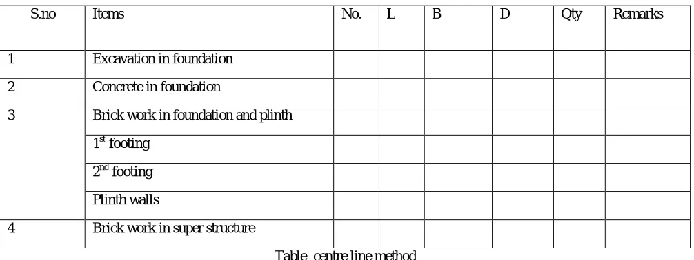
Table centre line method
B. Detailed Estimate
Detailed cost estimates are prepared carefully. This calculating detailed the cost of various item works that constitutes the whole project. Detailed estimates are done when the detailed working drawings are prepared along with the specifications if there is any mistaken rough cost estimate then it will eliminate in detail cost estimates. This are then submit to the competent authority for obtaining technical sanction the whole project is divided into different items of work or activities. The quantity of each item will be calculated from drawing as accurately as possible this procedure is known as taking out quantities.
S.no Items No. L B D Qty Remarks
1 Excavation in foundation
2 Concrete in foundation
3 Brick work in foundation and plinth
1st footing
2nd footing
Plinth walls
s.no description no.s rate unit amount total amoutnremarks
[image:5.612.206.405.76.214.2]
Table Detailed Estimate
IV. MANUAL CALCULATIONS & DEFINITIONS A. Footing
Footings are an important part of foundation construction. They are typically made of concrete with re bar reinforcement that has been poured into an excavated trench. The purpose of footings is to support the foundation and prevent settling. Footings are especially important in areas with troublesome soils.
The construction of footings is best left to the process that can assess the soil conditions and beside on the proper depth and width for the footings as well as the proper placement. The dimension of the footings also depends on the size and type of structure that will be build placement of footings is crucial to provide the proper support for the foundation and ultimately the structure.
B. Column
A column or pillar in architecture and structural engineering is a structural element that transmits, through compression the weight of the structure above to other structural elements below. In other words, a column is a compression member. The term column applies especially to a large round support (the shaft of the column) with a capital and a base or pedestal which is made of stone, or appearing to be so. A small wooden or metal support is typically called a post, and supports with a rectangular or other non-round section are usually called piers. For the purpose of wind or earthquake engineering, columns may be designed to resist lateral forces. Other compression members are often termed "columns" because of the similar stress conditions. Columns are frequently used to support beams or arches on which the upper parts of walls or ceilings rest. In architecture, "column" refers to such a structural element that also has certain proportional and decorative features. A column might also be a decorative element not needed for structural purposes; many columns are "engaged", that is to say form part of a wall.
C. Beams
A beam is a structural element that primarily resists loads applied laterally to the beam's axis. Its mode of deflection is primarily by bending. The loads applied to the beam result in reaction forces at the beam's support points. The total effect of all the forces acting on the beam is to produce shear forces and bending moments within the beam, that in turn induce internal stresses, strains and deflections of the beam. Beams are characterized by their manner of support, profile (shape of cross-section), length, and their material.
Beams are traditionally descriptions of building or civil engineering structural elements, but any structures such as automotive automobile frames, aircraft components, machine frames, and other mechanical or structural systems contain beam structures that are designed to carry lateral loads are analyzed in a similar fashion.
D. Manual Calculation
1) Earthwork Excavation: Soils are the most complex of all engineering materials, and the excavation of soil is the most hazardous of all construction occupations. Soil type is used by construction workers to properly excavate the ground for utility and other purposes. Different methods of construction are permitted that include sloping, shoring, shielding, and benching of the soil for protection. We employed sloping for soil excavation here on site.
a) Earth work Excavation of footing. L x B x D=4’6”x3’6”x6
E. Concrete
1) Before concreting commences, proper access and working platform for workers involved in placing, compacting and finishing
shall be ensured.
2) 40mm immersion type needle vibrator shall be used for compaction of concrete.
3) Effective distances between the reinforcement shall not be disturbed while concreting.
4) Corrective action shall be immediately taken in case of loosening of supports and fixings due to vibrations transmitted to the formwork.
5) Concrete shall be laid up to the required levels as per drawing (GFC) After Concreting.
6) Once the concreting is complete, the verticality shall be checked.
7) If any deviations are found, then the supports shall be adjusted and shall be straightened.
8) De-shuttering:
9) After 12-24 hrs. of casting the concrete, de-shuttering shall be done by loosening the nut bolts. The frames shall be smoothly struck, so that the concrete edges are not damaged.
10) All the ties, supporting arrangements should be loosened and removed gradually.
11) Use of crowbars to open the forms shall be avoided at all costs. Cement concrete in bed base (1:4:8)
(NO.S x L x B x D)
= (1x1.36x1.06x0.10) =0.14cu.m Concreting in footing
(L x B x D)
(1.36x1.06x0.30)= 0.43cu.m Concreting of trapezoidal footing
(L x B x D) = 0.93x0.66x0.30 = 0.18cu.m Concreting of pedestal
(L x B x D) = 0.50x0.50x1.21 = 0.30 cu.m Concrete of column
0.45x2.74x0.22 = 0.27 cu.m
F. Backfilling
1) Scope: Covers the activity of quarry dust filling, earth filling in the trenches of foundations, plinth, under floors in all towers.
G. Manpower
1) Engineer: As required
2) Supervisor: As required
3) Labour: As required
H. Equipment
1) 1MT mechanical vibratory compactor (Diesel Operated)
2) Levelling instrument
3) Rapid moisture meter
4) Field density core cutter with dolly and hammer
I. Types of Backfilling 1) Dry fills
2) Cement rock fills
3) Hydraulic sand fill
J. Dry Fills
Generally consists of surface sand, gravel, open pit waste rock, underground waste rock, smelter slag generally unclassified except to remove large boulders usually transported underground by dropping down a raise from surface directly into a slope or to a level where it is hauled to a slope with an LHD or trucks. Usually contains some adsorbed surface moisture. Suitable for mechanized cut and fill or Avoca or other method where structural backfill is not required.
K. Fixing Of Reinforcement
1) Avoid substitution of bars, if unavoidable check for over consumption.
2) Do not use tack weld at cross points.
3) Avoid excessive chairs. Arrive at optimum spacing of chairs by trials.
4) Use cut pieces/welded scraps for chairs. Avoid using full length bars for making chairs.
5) Use spider beam to lift heavy cages.
6) Check spacing's, number of bars, location of bars etc. before start of concrete.
7) Fix the bars accurately with specified cover of size and grade.
8) Plan best fixing sequence to achieve accuracy and to accommodate form work, void formers, starter bars etc.
9) Ensure inspection of reinforcement fixing intermittently to avoid redoing.
10) Avoid large time gap between the concrete pours to prevent deterioration of projected reinforcement Steel Reinforcement bars for footing mesh
Length of bar X=1.36 Y=1.06 No. of bars
X= y/6” = (1.06/0.15+1) = 8.066 ~ 9 Bars Y= x/6” = (1.36/0.15+1) = 10.06 ~11 Bars Reinforcement of Column & footing
Bar length = (Column leg + Footing pit + Column Height + overlap) = 2.5+5.8+10+2.5 = 20.8ft (6.34Mts)
No. of Bars
16mm=4bars 12mm=4bars
Weight of Bars for Footing Mesh (D2/162 x Length of Bars x No. of Bars) Weight of bars of 16mm diameter (162)/162x 12.19x1 = 19.26kg
19.26 x 2 = 38.52 kg Weight of bars of 12mm diameter (122)/162 x 12.19 x 1 = 21.67 kg
L. Column Calculation
Column in Concrete : L x B x D
0.76 x 0.22 x 2.74 = 0.45 m3 Length of the bar
L+ Over Lapping L = 10+2.5 = 12.5m
16 diameter @16 mm No. of stirrups
Height of stair case = 10’ Mid landing = 4’10”
Landing depth = 5”, Breadth = 3”, Length = 7’ Inclined Length = 9’, Depth = 5”, Breadth = 3’6” Riser = 6”
Tread = 10” Step length = 3’6” Inclined depth = 1’
2.74 x 0.12 x 1.06 = 0.34 cu.m 0.34 x 2 = 0.68 cu.m
Inclined volume = L x B x D = 9 x 5 x 3.5 = 157.5ft Step volume
= 6 x 10 x 12
= 0.15 x 0.25 x 0.30 = 0.011 = 0.011x 18 = 198 cu.m Landing volume
L x B x D
= 2.13 x 0.91 x 0.12 = 0.23 cu.m 50 x D = for hooks
Length of bar
X = 0.91+2.74+0.91 X = 4.56 m
Crank length = 0.42x 0.01 = 0.042 = 4.56+0.042+ 0.042 = 4.64 Y = 0.9150(0.010) + 50(0.010)
= 1.06+0.50+0.50 Y = 2.06m
No. of Bars
Y = Length of X / Spacing Y = 4.56 / 0.15
= 30.4 ~ 31 for half landing = 31 x 2 = 62 for full landing X = Length of Y / Spacing = 2.06 / 0.15
= 14 bars for half landing = 14 x 2 = 28 for full landing
M. Beam Calculation
Volume of concrete L x B x D
= 7.01 x 0.22 x 0.38 = 0.58cu. m
Length of bars
7.02+2.5 = 9.5 mts No. of bars
16bars @ 16 diameters Weight of bars
1.58 x 16 x 12 = 303.36 kg
No. of stirrups
Length of beam / spacing = 7.01/0.15 = 46.73 = 46.37 ~ 47 stirrups Weight of stirrups
82/162 = 0.39 kg = 0.39 x 47 = 18.33kgs
1) Slab calculation
Slab area = 22.5 x 36.5 = 821ft (250 m)
Deduction of stair case & lift = 7 x 15.33 = 107.31ft (32.71 m)
Total slab area= 821-107.31=713.69 ~ 714 L x B x D = 714 x 0.42 = 300 cu.ft
= 48.81 ~ 49bags 300/ 35.28 = 8.49 cu.m volume of cement = 8.49 x 5.75 = 48.81 bags
fine aggregate = 8.49 x 0.98 = 8.32 tonnes Coarse aggregate
= 8.49 x 0.93
= 7.89 tonnes Length = 11mts
Length of bars = length+0.42D x no. of Cranks – 2 x covers + over lapping = 11+ (0.42x 0.008) x 6-2 x 0.025 + 50 x 0.008
= 11.37mts
No. of bars = Length / Spacing
= 11.37 / 0.15
= 75 bars (includes L/4) Breadth = 6.85mts
=L+0.42D x no. of Cranks -2xcovers +overlapping = 6.85 + (0.42x0.010) x 4 -2 x 0.025 + 50 x 0.010 = 7.31mts No. of bars
= Breadth / spacing = 7.31 / 0.15 = 48 bars Weight of bars
= 0.69 x 48 x 12 =355.55 kg
N. Preparation
1) Material used for plastering viz cement, sand and water shall be inspected and tested prior to their incorporation into the works. Sand shall be sieved prior to use. Check the silt content of the sand which should not exceed more than 8 %. In case the silt content is more than 8%, then it should be washed thoroughly before use.
2) Steel scaffolding with necessary safety arrangements shall be erected to carry out works at height. Erected scaffolding shall be checked and approved by SPCL construction safety engineer prior to its use.
3) All doors, window frames to be checked for line, level, plumb and holdfasts before starting the plastering work. Check if all the holdfasts are fixed properly for door frames. Opening shall be checked with approved templates for dimensions.
4) Loose mortar or dust sticking to masonry walls shall be removed by brushing. Concrete surfaces shall be cleaned and hacked with hacking machine to get proper bonding. Chicken mesh shall be provided at the junction of masonry and RCC for proper bonding, with an overlap of 15cm.
5) Surface to receive plaster should be made sufficiently wet on previous day of plastering.
6) Tie rod holes in concrete members to be grouted prior to plastering work.
7) All related MEP work shall be completed prior to starting of plastering. Electrical conduits, junction boxes and plumbing pipes shall be fixed in place properly.
8) Ensure proper hacking with machine over the concrete surfaces for proper bonding.
9) Check for dimensions, rectangularity and verticality of the room to receive plaster.
10) Put the bull marks of appropriate thickness on the surface to receive plastering.
O. Mesh To Walls
Approved mesh will be laid single layer of GI expanded metal mesh of 0.35 mm nominal thickness and 125mm width shall be provided at the junctions of the masonry and concrete members and also over the electrical conduits exceeding more than two numbers together. The lap should be equal on either sides of the junction, properly stretched and nailed measuring equal thickness/width on plaster on both sides of the mesh.
P. Use of Mesh Walls
a) Meshes are often used to screen out unwanted things, such as insects. Wire screens on windows and mosquito netting can be
considered as types of meshes.
b) Wire screens can be used to shield against radio frequency radiation, e.g. in microwave ovens and Faraday cages.
c) Metal and nylon wire mesh filters are used in filtration
d) Wire mesh is used in guarding for secure areas and as protection in the form of vandal screens.
e) Wire mesh can be fabricated to produce park benches, waste baskets and other baskets for material handling.
f) Woven meshes are basic to screen printing.
g) Surgical mesh is used to provide a reinforcing structure in surgical procedures like inguinal hernioplasty, and umbilical hernia repair.
h) Meshes are also used as drum heads in practice and electronic drum sets.
i) Human animal trapping now use woven or welded wire mesh cages to trap wild animals in domestic areas, such as raccoons,
skunks, etc.
Q. Application Procedure
Mortar mixing: 20mm thick cement plastering on external surface of masonry or concrete surface shall be done in two layers.
1) First Coat
a) One portion of cement shall be mixed with five portions of screened, clean, fine sand as approved, by volume (1:5) and mixed till uniform colour is formed.
b) And add water proofing compound to the water as per the manufacturer’s instructions and mix well till the required consistency is achieved. Mixture shall be made in small quantities as required and applied within 15 min of mixing.
c) And continue plastering with a 12 mm thickness rough finish.
2) Final Coat
b) External plastering shall be applied from top to bottom, in that fashion.
c) Plastering guides using nylon threads are made to ensure uniform thickness of plastering.
d) Mortar shall be applied on the surface, floated with wooden float and shall be levelled with straight edge to the required thickness.
e) All the dimensions, line, level, plumb and diagonal must be checked regularly to ensure the conformity of the on-going work as per drawings.
f) Dimensions of all the openings shall be checked during plastering.
g) Plaster shall be made rough with wire when still green to ensure proper bonding of tiles later wherever applicable.
h) Necessary grooves in plastering both horizontally and vertically as per elevation drawings shall be done in final coat of plastering.
Outer wall 22.5+36.5+36.5 = 95.5 = 95.5 x 10 = 955sq.ft = 955 x 0.75 = 716.25cu.ft No. of bricks
= 716.25 /0.062 = 11552.41 bricks
Inner wall 15’3” x 3 = 45.45 sq.ft =45.45 x 10 = 454.5sq.ft 454.5 x 0.75 = 340.87cu.ft No. of bricks
= 340.87 / 0.062 = 5497.98 bricks Plastering
Area of outer wall = 716.25 sq.ft Area of inner wall = 340.87sq.ft Total plastering = 716.25+340.87
= 1057.12cu.ft
Converting cubic feet to metre 1057.12/3.28 = 322.29m Plastering slab area
= 322.21+ 97.52+101.84 = 521.57sq.ft
= 521.57/10.764
= 48.45sq.m 48.45 x 0.012 = 0.58m3
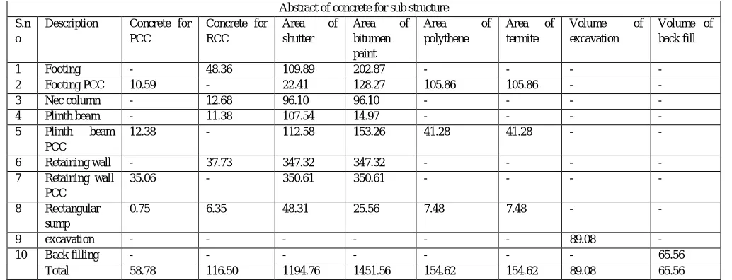
Abstract of Concrete For Sub Structure (manual):
Abstract of concrete for sub structure S.n
o
Description Concrete for PCC
Concrete for RCC
Area of
shutter
Area of
bitumen paint
Area of
polythene
Area of termite
Volume of
excavation
Volume of back fill
1 Footing - 48.36 109.89 202.87 - - - -
2 Footing PCC 10.59 - 22.41 128.27 105.86 105.86 - -
3 Nec column - 12.68 96.10 96.10 - - - -
4 Plinth beam - 11.38 107.54 14.97 - - - -
5 Plinth beam
PCC
12.38 - 112.58 153.26 41.28 41.28 - -
6 Retaining wall - 37.73 347.32 347.32 - - - -
7 Retaining wall PCC
35.06 - 350.61 350.61 - - - -
8 Rectangular sump
0.75 6.35 48.31 25.56 7.48 7.48 - -
9 excavation - - - 89.08 -
10 Back filling - - - 65.56
[image:11.612.49.566.527.725.2]Total 58.78 116.50 1194.76 1451.56 154.62 154.62 89.08 65.56
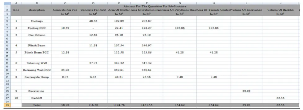
R. Abstracts of Software
S. Schedule Of Slab
Slabsare constructed to provide flat surfaces, usually horizontal in building floors, roofs, bridges, and other types of structures. The slab may be supported by walls or by reinforced concrete beams usually cast monolithically with the slab or by structural steel beams or by columns, or by the ground. Slabs are classified into 16 types.
SLAB MARK
TYPE REINFORCEMENT ALONG
SLAB THICKNESS
SHORT SPAN (MAIN)
LONG SPAN (DISTUBUTION BARS)
REMRKS
S1 TWO WAY 4.5” T10 @6”C/C T10 @7”C/C ALT CRANK
ALT EXT
S2 ONE WAY 4.5” T10 @6”C/C T10 @7”C/C ALT CRANK
ALT EXT IN SHORTER DIRECTION
S3 TWO WAY 5” T10 @6”C/C T10 @6”C/C ALT CRANK
[image:12.612.61.550.87.265.2]ALT EXT
Table Schedule of slab
B. Bill of Reinforcement for SUPER-Structure(Software)
D. Bill of Reinforcement for SUB-Structure(Manual)
BILL OF QUANTITIES OF REINFORCEMENT SUB STRUCTURE S.
N O
DESCRIPTION UNITS RATE IN
RUPEES
TOTAL QUANTITY TOTAL
AMOUNT REMARKS WT OF STEEL BARS IN (KGS) NO OF BARS 12MM LENGTH
1 8mm dia bars Kgs 48 2307.240 79 110747.52
2 10mm dia bars Kgs 47 3154.920 248 148281.24
3 12mm dia bars Kgs 47 2650.560 69 124576.32
4 16mm dia bars Kgs 47 1403.040 94 65942.88
5 20mm dia bars Kgs 47 236.160 5 11099.52
[image:14.612.52.557.87.262.2]Total 9751.920 kgs 495 460647.48
Table 23 Bill of Reinforcement substructure
E. Bill of Reinforcement for SUPER-Structure(Manual)
BILL OF QUANTITIES OF REINFORCEMENT SUPER-STRUCTURE S.N
O
DESCRIPTION UNIT
S
RATE IN RUPEES
TOTAL QUANTITY TOTAL
AMOUNT
REMARKS WT OF STEEL
BARS IN (KGS)
NO OF BARS 12MM L
1 8mm dia bars Kgs 48 12196.080 2584 585411.84
2 10mm dia bars Kgs 47 10294.560 1356 483844.32
3 12mm dia bars Kgs 47 17233.920 1622 809994.24
4 16mm dia bars Kgs 47 21500.640 1134 1010530.08
5 20mm dia bars Kgs 47 1416.960 48 66597.12
[image:14.612.42.567.288.454.2] [image:14.612.41.575.488.716.2]Total 62642.160 kgs 6744 2956377.6
Table Bill of Reinforcement for super structure
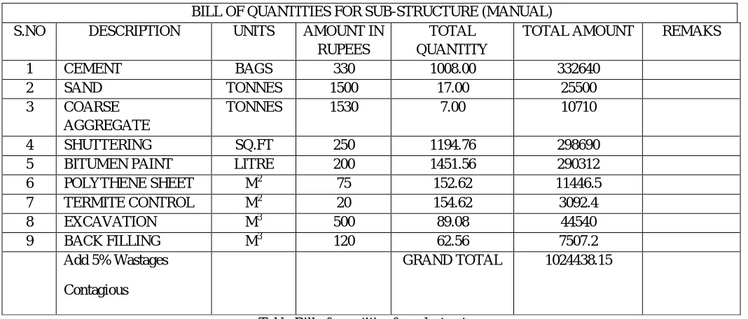
F. Bill of Quantities for SUB-STRUCTURE(Manual)
BILL OF QUANTITIES FOR SUB-STRUCTURE (MANUAL)
S.NO DESCRIPTION UNITS AMOUNT IN
RUPEES
TOTAL QUANTITY
TOTAL AMOUNT REMAKS
1 CEMENT BAGS 330 1008.00 332640
2 SAND TONNES 1500 17.00 25500
3 COARSE
AGGREGATE
TONNES 1530 7.00 10710
4 SHUTTERING SQ.FT 250 1194.76 298690
5 BITUMEN PAINT LITRE 200 1451.56 290312
6 POLYTHENE SHEET M2 75 152.62 11446.5
7 TERMITE CONTROL M2 20 154.62 3092.4
8 EXCAVATION M3 500 89.08 44540
9 BACK FILLING M3 120 62.56 7507.2
Add 5% Wastages
Contagious
GRAND TOTAL 1024438.15
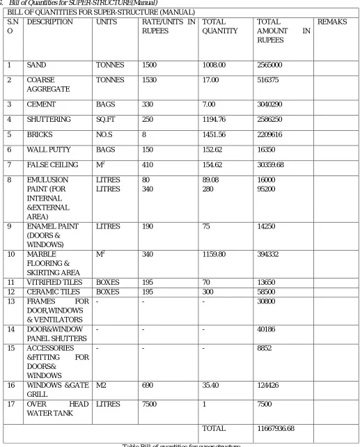
G. Bill of Quantities for SUPER-STRUCTURE(Manual)
BILL OF QUANTITIES FOR SUPER-STRUCTURE (MANUAL) S.N
O
DESCRIPTION UNITS RATE/UNITS IN
RUPEES
TOTAL QUANTITY
TOTAL
AMOUNT IN
RUPEES
REMAKS
1 SAND TONNES 1500 1008.00 2565000
2 COARSE
AGGREGATE
TONNES 1530 17.00 516375
3 CEMENT BAGS 330 7.00 3040290
4 SHUTTERING SQ.FT 250 1194.76 2586250
5 BRICKS NO.S 8 1451.56 2209616
6 WALL PUTTY BAGS 150 152.62 16350
7 FALSE CEILING M2 410 154.62 30359.68
8 EMULUSION
PAINT (FOR INTERNAL &EXTERNAL AREA)
LITRES LITRES
80 340
89.08 280
16000 95200
9 ENAMEL PAINT
(DOORS & WINDOWS)
LITRES 190 75 14250
10 MARBLE
FLOORING & SKIRTING AREA
M2 340 1159.80 394332
11 VITRIFIED TILES BOXES 195 70 13650
12 CERAMIC TILES BOXES 195 300 58500
13 FRAMES FOR
DOOR,WINDOWS & VENTILATORS
- - - 30800
14 DOOR&WINDOW
PANEL SHUTTERS
- - - 40186
15 ACCESSORIES
&FITTING FOR
DOORS& WINDOWS
- - - 8852
16 WINDOWS &GATE
GRILL
M2 690 35.40 124426
17 OVER HEAD
WATER TANK
LITRES 7500 1 7500
[image:15.612.46.563.79.721.2]TOTAL 11667936.68
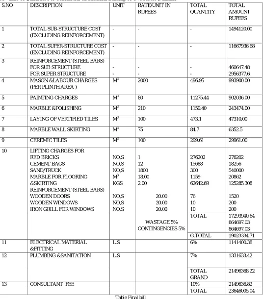
VI. COMPARISION OF BILLS A. Bills Of Quantities For Commercial &Residential Building Of G+5 Floors (Manual)
S.NO DESCRIPTION UNIT RATE/UNIT IN
RUPEES TOTAL QUANTITY TOTAL AMOUNT RUPEES
1 TOTAL SUB-STRUCTURE COST
(EXCLUDING REINFORCEMENT)
- - - 1494120.00
2 TOTAL SUPER-STRUCTURE COST
(EXCLUDING REINFORCEMENT)
- - - 11667936.68
3 REINFORCEMENT (STEEL BARS)
FOR SUB STRUCTURE FOR SUPER STRUCTURE
- - - - - - 460647.48 2956377.6
4 MASON &LABOUR CHARGES
(PER PLINTH AREA )
M3 2000 496.95 993900.00
5 PAINTING CHARGES M3 80 11275.44 902036.00
6 MARBLE &POLISHING M3 210 1159.40 243474.00
7 LAYING OF VERTIFIED TILES M3 100 473.1 47310.00
8 MARBLE WALL SKIRTING M3 75 84.7 6352.5
9 CEREMIC TILES M3 100 299.61 29961.00
10 LIFTING CHARGES FOR
RED BRICKS CEMENT BAGS SAND/TRUCK
MARBLE FOR FLOORING &SKIRTING
REINFORCEMENT (STEEL BARS) WOODEN DOORS
WOODEN WINDOWS
IRON GRILL FOR WINDOWS
NO,S NO,S NO,S M3 KGS NO,S NO,S NO,S 1 12 1800 18.00 2.00 20.00 20.00 20.00 WASTAGE 5% CONTINGENCIES 5% 276202 15688 300 1159 62642.69 76 10 10 276202 18256 540000 20862 125285.308 1520 200 200
TOTAL 17293940.64
864697.03 864697.03
G.TOTAL 19023334.71
11 ELECTRICAL MATERIAL
&FITTING
L.S 6% 1141400.38
12 PLUMBING &SANITATION L.S 7% 1331633.42
TOTAL GRAND
21496368.22
13 CONSULTANT FEE 10% 2149636.82
[image:16.612.40.576.99.709.2]TOTAL 23646005.04
VII. CONCLUSION
A. It was an absolute privilege to undergo my training at CREATIVE ENGINEERING infrastructure pvt. site works at GULZAR
HOUSE construction of COMMERCIAL + RESIDENTIAL BUILDING. It was indeed a learning experience and went a long way in increasing my knowledge and skill. It was wonderful to work alongside a highly skilled and experienced workforce at one of the major construction sites in the country. It gave me an opportunity to learn about various aspects of civil engineering. I learnt about the implementation of various techniques and methods being used for construction. I also learnt how the entire work site is managed and how the various activities are planned.
B. I feel proud to have worked at this project and I am thankful to CREATIVE ENGINEERING infrastructure pvt.ltd for having
given me the opportunity.
C. In the process of carrying out this project, we learnt to apply the theoretical aspects of estimation on a live project. We have learnt the process of Estimation and Costing and we understood that it is an essential aspect in a project for the arrangement of financial resources necessary for the completion of the job.
D. Our calculation it are based on precise measurements which gave us approximate and accurate values. The structural estimate had been prepared in detail such that the values can be used in the actual project being carried out.
E. Also, the abstract of the estimated cost was prepared such that the current on going rate per unit of each item of work were considered. Hence the estimated costs of the structural requirements of the project are accurate too.
F. Therefore, this project is not a rough, but fairly accurate in its results of both the estimated quantities as well as the estimated cost, and is quite useful for the ongoing project on which it is made. we compared both with Software and manual calculations and we got difference amount in both, software is more accurate than manual, in software we used SSR(STANDARD SCHEDULE RATES) and in manual we used market present rates, as per rates we got more amount than SSR amount.
REFERENCES
[1] Flyvbjerg, Bent (2002). "Underestimating Costs in Public Works Projects: Error or Lie?” Journal of the American Planning Association. 68 (3): 279–295. [2] Garcia De Soto, B.; Adey, B. T.; Fernando, D. (2014). "A process for the development and evaluation of preliminary construction material quantity estimation
models using backward-elimination-regression and neural networks". Journal of Cost Analysis and Parametric. 7(3): 180– 218. Doi:10.1080/1941658X.2014.984880.
[3] Standard Estimating Practice Sixth Edition, American Society of Professional Estimators, Bni Publications, Inc, 2004, ISBN 1557014817, Pg 98-99 [4] Frederic C. Jelen, James H. Black, Cost and Optimization Engineering, Third Edition, McGraw-Hill Book Company, 1983, Page 324
[5] Garold D. Oberlender and Steven M. Trost, “Predicting Accuracy of Early Cost Estimates Based on Estimate Quality”, Journal of Construction Engineering and Management / Volume 127/ Issue 3/ TECHNICAL PAPERS, American Society of Civil Engineers.
[6] GAO Cost Estimating and Assessment Guide, Best Practices for Developing and Managing Capital Program Costs, GAO-09-3SP, United States Government Accountability Office, March 2009.
[7] Philip R. Waier, PE, et al, RSMeans Building Construction Cost Data 70th Annual Edition, RSMeans a division of Reed Construction Data, ISBN 978-1-936335-29-9, Pg vii.
[8] Cost Estimating Guide for Program and Project Management, U.S. Department of Energy, Office of Management, Budget and Evaluation, DOE G 430.1-1X, April 2004.
[9] Bureau of Labour Statistics, U.S. Department of Labour, Occupational Outlook Handbook, 2012-13 Edition, Cost Estimators, on the Internet at http://www.bls.gov/ooh/business-and-financial/cost-estimators.htm (visited October 21, 2012).
[10] A Guide to the Project Management Body of Knowledge (PMBOK Guide) Third Edition, An American National Standard, ANSI/PMI 99-001-2004, Project Management Institute, Inc, 2004, ISBN 1-930699-45-X.
[11] Cost Estimate Classification System, AACE International Recommended Practice No. 17R-97.
[12] Marilyn Phelan, AIA, et al, RSMeans Square Foot Costs, RSMeans a division of Reed Construction Data, ISBN 978-1-936335-74-9, Pg v.
[13] GAO Cost Estimating and Assessment Guide, Best Practices for Developing and Managing Capital Program Costs, GAO-09-3SP, United States Government Accountability Office, March 2009, Pg 6.
[14] "Provoc - Glossary of Common Project Control Terms," The Association of Cost Engineers (ACostE), http://www.acoste.org.uk, pg 7
[15] Philip R. Waier, PE, et al, RSMeans Building Construction Cost Data 70th Annual Edition, RSMeans a division of Reed Construction Data, ISBN
AUTHOR BIOGRAPHY
A. Mohammed Furkhan (GEO-TECH ENGINEER ) Assistant Professor, Department Of Civil Engineering, Lords Institute Of Engineering & Technology.
B. Mushtaq Ahmed (Civil Engg) Scholar of Lords Institute Of Engineering & Technology.
C. Najam Uddin (Civil Engg) Scholar of Lords Institute Of Engineering & Technology.
D. Mir Mahmood Ali (Civil Engg) Scholar of Lords Institute Of Engineering & Technology.