warwick.ac.uk/lib-publications
Permanent WRAP URL:http://wrap.warwick.ac.uk/78804
Copyright and reuse:
This thesis is made available online and is protected by original copyright. Please scroll down to view the document itself.
Please refer to the repository record for this item for information to help you to cite it. Our policy information is available from the repository home page.
AND TECHNIQUES FOR THE STRUCTURING OF DATA AND FOR MODELLING ITS BEHAVIOUR
Volume I of III
by PAUL BARRIE FELDMAN B.Sc(Hons)
a PhD thesis
UNIVERSITY OF WARWICK COVENTRY, ENGLAND
SCHOOL OF INDUSTRIAL AND BUSINESS STUDIES
Title
VOLUME I
LIST OF ILLUSTRATIONS ACKNOWLEDGEMENTS
SOURCE ACKNOWLEDGEMENTS SHORT SUMMARY
PART I. OVERVIEW
A. INTRODUCTION TO THESIS
Al SUMMARY OF THESIS
Al.l The Research
Al.l.l Action Modelling
Al.I.2 Entity Model Clustering
AI.I.3 Parallelism Between Data and Activity Modelling
AI.I.4 Diagramming Tool
AI.I.S Knowledge Engineering AI.I.6 Research Problems Al.4 Description of Document AI.4.1 Overview Part
AI.4.2 Research Part AI.4.3 Conclusions Part
A2 SYSTEMS DEVELOPMENT AND ITS ENVIRONMENT
A2.1 Introduction
A2.2 System Life Cycle A2.3 Frameworks
A2.4 Methodologies
A2.S Analysis Approaches A2.6 Data Modelling
A2.7 Activity Modelling
A2.8 Automation of Development
A2.9 Other Aspects of System Development A2.9.1 Good Design Principles
A2.9.2 Prototyping
A2.9.3 Quality of Information Systems A2.9.4 Time
A2.9.S Decision Support Systems and Artificial Intelligence
A2.10 The Research in Perspective
- 1
VOLUME II
PART II RESEARCH
B ACTION MODELLING
Bl INTRODUCTION TO CHAPTER
B2 WHY ACTION MODELLING?
B2.1 Functional Instability B2.2 Method Simplicity
B2.3 Levels of Activities
B2.4 Development Emphasis Shift to Analysis
B3 ACTION MODELLING CONCEPTS
B 3 • 1 Ac t ion s
83.2 Associations Between Actions B3.2.1Optiona1ity
B3.2.2 Cardinality
B3.3 Events and Triggering B3.4 Conditions
B3.4.1 Pre and Post Conditions B3.4.2 Exclusivity
B3.4.3 Floating Conditions and Actions B3.4.4 Design Justification for Condition
Specification
B3.4.5 Premises, Conclusions and Probabilities B3.5 Behavioural Hierarchies
B3.6 Duplication of Use
B3.7 Indivisible Actions and Selection Critera B3.8 Information Flow
B4 ANALYSIS OF ACTIONS
B4.1 Inputs to Action Analysis B4.2 Outputs from Action Analysis
B4.3 Action Model of Action Analysis Tasks B4.4 Action Analysis Tasks
B4.1 1 Identify Actions
B4.4.2 Decompose Actions Where Necessary B4.4.3 Identify Pre and Post Conditions 84.4.4 Identify Dependencies
B4.4.5 Abstract Model B4.5 Other Points
B5 EXAMPLES OF ACTION MODELLING
85.1 Book Holiday
B5.2 Organise Conference B5.3 MYCIN Rules
2
B6 DETAILS OF USE
B6.1 Experience at International Paint
B7 BENEFITS OF ACTION MODELLING
B7.1 Improvement to Understanding of Data and its Behaviour
B7.2 Diagrammatic Specification and Procedurality B7.3 Information for Design
B7.4 Action Modelling for Knowledge-Based Systems B7.4.1 Facts
B7.4.2 Rules
B7.4.3 Action Modelling of Rules B7.5 Finding Elementary Processes 87.6 Temporal Modelling
B7.7 Substitute for Other Behaviour Modelling Techniques
88 COMPARISON OF ACTION MODELLING WITH OTHER
BEHAVIOUR MODELLING TECHNIQUES 88.1 Techn iques
B8.1.l Entily Life Histories/Entity State Diagrams 88.1.2 Access Path Diagrams/Process Logic Diagrams B8.1.3 Data/Information Flow Diagrams
B8.1.4 Petri-Nets
B8.1.S Non-Diagrammatic Techniques B8.2 Methodology Based Techniques
88.2.1 ACM/PCM - Active and Passive Component Modelling
B8.2.2 Remora - Richard and Rolland
88.2.3 Information Engineering Before Action Modelling
B8.3 Behaviour Modelling in Other Methodologies
88.3.1 LSDM - LBMS Structured Development method and
SSADM - Structured Systems Analysis and Design Method
8B.3.2 JSD - Jackson System Development
88.3.3 ISAC
88.3.4 ClAM - Conceptial Information Analysis Methodology
88.3.5 NIAM - Nijssen's Information Analysis Method
88.3.6 Structured Systems Analysis (SSA) - de Marco and Gane and Sarson
B8.3.7 02S2 - Macdonald and Palmer
B9 FURTHER RESEARCH
89.1 Action Normalisation
B9.2 Actions and Dataflow Architectures
B9.3 Action Modelling and Decision Support Systems B9.4 Automatic Generation of Software
from Action Models
- 3
C ENTITY MODEL CLUSTERING
Cl INTRODUCTION TO CHAPTER
C2 WHY ENTITY MODEL CLUSTERING?
C2.1 The Problem C2.2 The Solution
C3 ENTITY MODEL CLUSTERING CONCEPTS
C3.l Models and Diagrams C3.2 Clustered Entity Model
C3.3 r1ajor Entity Types and Minor Entity Types C3.4 Subject Areas
C3.5 Relationships in a Clustered Entity Model C3.6 Subject Area Diagrams
C3.7 Cartographica1 Analogy to The Use of a Clustered Entity Model
C3.8 Abstractions on Entity Relationship Models In Entity Model Clustering
C4 CLUSTERING AN ENTITY RELATIONSHIP MODEL
C4.1 Methods of Formation/Derivation C4.1.1 Finding Major Entity Types C4.1.2 Forming Subject Areas
C4.1.3 Inter-Subject Area Relationships
C4.2 Algorithm for Clustering an Entity Relationship Model
C4.3 Practical Guidelines
C5 EXAMPLES OF CLUSTERED ENTITY MODELS
C5.1 Find Major Entity Types C5.2 Find Subject Areas
C5.3 Major Entity Type Iteration C5.4 Subject Area Iteration
C6 DETAILS OF USE
C6.1 Whitbread & Company PIc
C6.2 Prudential Assurance Company Ltd C6.3 International Paint
C6.4 Sedgwick Insurance Brokers Ltd C6.S Calor Gas & Northern Gas
C6.4 James Martin Associates
C7 BENEFITS OF ENTITY MODEL CLUSTERING
C7.1 Highlights Major Entity Types
C7.2 Stability and Correctness of Models C7.3 Enables Views of Models to be Produced
C7.4 Eases The Use of End-User Computing
C7.S Use of Entity Model Clustering In Information Strategy Planning
4
C7.6 Defines Boundaries Area Boundary Formation:
C7.6.l Extra-Dimensional Functions Subject Areas C7.6.2 Major Entity Types
C7.6.3 Form 'First Cut' Mainstream Systems C7.6.4 Form Business Areas/Business Systems C7.6.5 Manipulate Results
C7.7 Aids Automation of Entity Relationship Modeling
C8 COMPARISON OF ENTITY MODEL CLUSTERING WITH
SIMILAR TECHNIQUES
CB.l Grouping by Cluster Analysis C8.2 Lockheed Technique
C9 FURTHER RESEARCH
C9.l Blueprinting Models C9.2 Entity Type Views
C9.3 Entity Model Clustering and Design Support C9.4 Automating Entity Model Clustering
D. PARALLELISM BETWEEN DATA & ACTIVITY MODELLING
Dl INTRODUCTION TO CHAPTER
D2 OBJECT SYMMETRY
D2.l Subject Areas and Functions D2.2 Logical Horizons and Processes D2.3 Entity Types and Actions
D2.4 Attributes and Indivisible Actions, Domains and Types of Indivisible Actions
D2.5 Other Objects D.2.5.1 Conditions etc D2.5.2 Associations D2.S.3 Entity States D2.5.4 Events
D3 ASSOCIATION SYMMETRY
D3.1 Associations in Activities D3.2 Associations in Data
D4 ACTION MODELLING REVISITED
D5 FURTHER RESEARCH
DS.l Atomic Data Modelling D5.2 Action Stability
DS.3 Specification of Business Rules
- 5
E. A DIAGRAMMER FOR THE PRODUCTION OF ENTITY TYPE MODELS
El INTRODUCTION TO THE DIAGRAMMER
E2 DIAGRAMMER PRINCIPLES AND CONSTRAINTS
E2.l Diagrammer and Micro-Computers E2.2 Graphics Package Constraints E2.3 Human Imitation
E2.4 Diagram Production Methods
E2.4.1 Interactive Diagram Production E2.4.2 Automatic Diagram Production E2.S Criteria for Diagram Production E2.6 Diagrammer Input
E2.7 Viewing Large Diagrams
E3 TECHNICAL DETAILS
E3.l Internal Representation of the Diagrams E3.2 Layout of Entity Types
E3.3 Relationship Connection E3.4 Viewing of Diagrams E3.S Manipulating Diagrams E4 USE OF DIAGRAMMER
6
VOLUME III
PART III CONCLUSIONS
F RESEARCH METHOD
Fl INTRODUCTION
F2 BACKGROUND TO RESEARCH
F3 RESEARCH HISTORY
G RESEARCH PROBLEMS
H CONCLUSIONS OF RESEARCH
I REFERENCES
X APPENDICES
Xl INFORMATION ENGINEERING AND OTHER CONCEPTS
Xl.l INTRODUCTION
Xl.2 INFORMATION ENGINEERING STAGES Xl.2.1 Introduction
Xl.2.2 Business Strategy Planning Xl.2.3 Information Strategy Planning Xl.2.4 Business Area Analysis
Xl.2.S Business System Design Xl.2.6 Technical Design
Xl.2.7 Construction Xl.2.S Transition Xl.2.9 Production
Xl.3 NOMENCLATURE AND DIAGRAMMING CONVENTIONS Xl.3.1 Nomenclature
Xl.3.2 Diagramming Conventions Xl.4 MACRO MODELLING
Xl.4.1 Decomposition and Abstraction
Xl.4.1.1 Decomposition and Abstraction in Activities Xl.4.1.2 Decomposition and Abstraction in Data
Xl.4.1.3 Summary
Xl.S SEPARATING SPECIFICATION AND DESIGN ISSUES
7
X2 ANALYSIS VIEWS AND EXTERNAL INTERACTIONS X2.l ANALYSIS VIEWS
X2.l.l Introduction
X2.l.2 Types of Analysis View X2.l.2.l Purpose Views
X2.l.2.2 Provided Information Views X2.l.2.3 Extra-Diamensional Views
X2.l.3 Manifestation of Views on Information X2.l.3.l Entity Types Shown
X2.l.3.2 Relationships Depicted X2.l.3.3 Attributes Shown
X2.l.3.4 Level of Abstraction Chosen X2.l.4 Importance of View Knowledge X2.2 EXTERNAL INTERACTIONS
X2-l X2-3 X2-3 X2-5 X2-5 X2-6 X2-7 X2-8 X2-9 X2-9 X2-ll X2-ll X2-l2 X2-13
X3 MODELLING CONCEPTS CONSIDERED AS PREDICATES X3-l
X3.1 PREDICATES X3-1
X3.2 APPLYING ELEMENTARY CONSTRUCTS TO DATA X3-4
X3.3 SYMMETRY WITH ACTIVITIES X3-l0
X4 GLOSSARY OF TERMS X4-l
X5 DETAILS OF PUBLISHED MATERIAL X5-1
X6 DIAGRAMMER LISTINGS X6-l
X7 INITIAL PROPOSAL X7-1
-Illustration Page
System Life Cycle
Evolutionary Life Cycle Quadrant Diagram
VOLUME I
Part I Chapter A
VOLUME II
Part II Chapter B
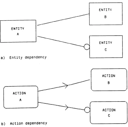
Figure B3.1 Action Modelling Conventions and Entity Modelling Conventions Figure B3.2 Action Dependency Example
Figure B3.3 Action Relationships, Entity Relationships & Optionality
Transitive Dependencies
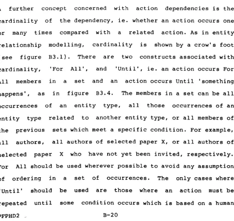
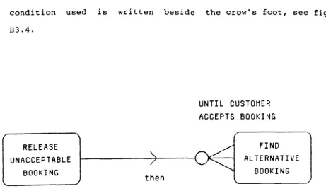
Figure B3.4 Examples of Cardinality
Figure B3.S Example of an Event Dependency
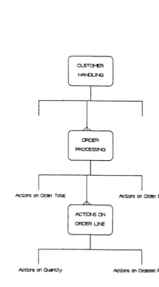
Figure B3.6 Example of Processing Decomposition Based on Data Structure
Figure B4.1 Action Model of Action Analysis Required Actions of Produce Order
Prepare Order Action Model Send Order Action Model Combined Action Model
Recursive V Iterative Dependency
Action Model & Entity Model Consistency
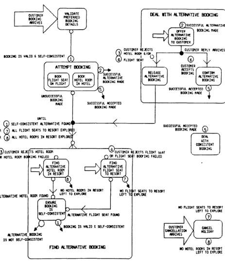
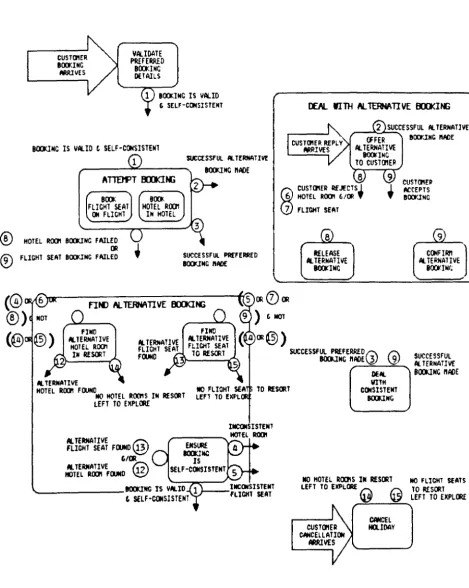
Figure BS.l Entity Relationship Diagram for Book Holiday Figure BS.2 Action Dependency Diagram for Book Holiday Hierarchy Matches Logical Horison of Booking
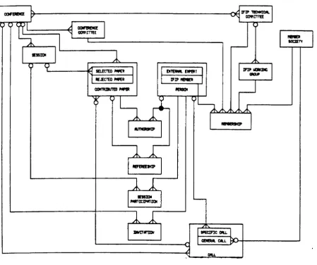
Figure BS.3 Procedural Diagram of Book Holiday Figure BS.4 Non-Procedural Diagram of Book Holiday Figure BS.S Entity Relationship Diagram for Organise
Conference
Figure BS.6 Process Decomposition of Conference Organisation
Figure BS.7 Action Dependency Diagram of Organise Conference
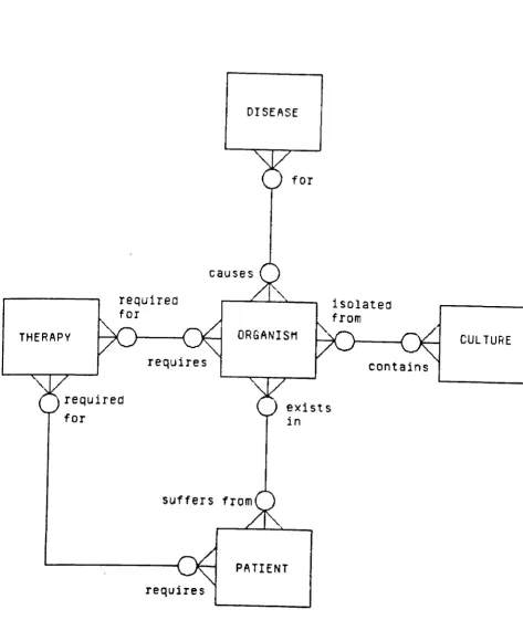
Figure BS.8 Entity Relationship Diagram of MYCIN Rules Figure BS.9 Action Dependency Diagram of MYCIN Rules Figure BS.10 Procedural Diagram of MYCIN Rules
- 9
Figure BS.ll Non-Procedural Diagram of MYCIN Rules Figure B6.1 Action Model of Production Planning Figure B7.1 DDSWP Quadrant Diagram
Entity Type/Process Meta-Model Exposition Figure B7.2 sextant Diagram
Chapter C Principal Entity Type
Classificatory Relationship & Entity Type Customers Subject Area
Customer-Customer Subjects Supplier-Purchases
Supplier-Purchase Order Inter-Diagram Connection
B-67 B-72 B-74 B-7S B-76 C-10 C-ll C-l4 C-1S C-16 C-17 C-l7 Aggregating Relationships
Figure C3.l A Three-Level Subject Area Hierarchy Figure C3.2 A Cartographical Analogy To a Clustered
C-18 & C-19 C-21 Entity Model
Figure C4.1 Entity Relationship Diagram of Clustering Objects
Figure C4.2 High-Level Action Dependency Diagram of Clustering
Figure C4.3 Detailed Action Dependency Diagram Of Clustering
Figure C4.4 Action Diagram of Clustering
Figure CS.l Example Entity Relationship Diagram Showing Logical Horizons
Figure CS.2 Example Clustered Entity Model
of Figure CS.l C-4S
Figure CS.3 Intermediate Stage of Clustering Process Multi-Dimensional View Of Organisations
Chapter D
Figure Dl.l Meta-Model of Information Engineering Conceptual Objects
Figure Dl.2 Meta-Model of Information Engineering Before My Research
Data Object v Activity Object Table Logical Horizon of Order Item
Sequence, Selection, Iteration Join Primitive
OR Primitive
10
Include Primitive
Relationship and Sequence Relationship and Parallel Optionality and Selection Cardinality and Repetition
Chapter E
Figure E2.1 A Typical Interactive Building Screen
Figure E2.2 An Example of the Output of the Diagrammer Figure E2.3 Ellis Style Relationship
Figure E2.4 Example of an Isomorphic Diagram No User Option Chosen
Figure E2.5 Example of Isomorphic Diagram
User-Option - Relationship Priority /Maximum Entity Priority Figure E2.6 Example of Isomorphic Diagram
User Option - Entity Priority
/Average Entity Priority Figure E3.1 Useful Start Sides
Figure E3.2 Intervening Entity Type Between End of Path & Target
Figure E3.3 Intervening Entity Type Between Two Entity Types
Figure E3.4 Example of Facility Menu
VOLUME III Appendices Appendix Xl Figure Xl.l Information Engineering Stages
Figure Xl.2 Major Object Types in the Methodology Information Engineering Conventions
Figure Xl. 3 Decomposition of ( a) an Entity Type (b) a Process
Figure Xl. 4 Association Between (a) an Entity Type (b) a Process
Figure Xl. 5 Decomposition of Activity Figure Xl. 6 Decomposition of Data
Figure Xl. 7 Logical Horizons and Subject Areas
Appendix X3 Attributes as Predicate Functions
Sequence, Parallel and Select as Predicates
11
Entity Type Predicate Function
Figure X3.1 Entity Relationship Model Expressed by Predicates
Figure X3.2 Entity Relationship Model Refinements Expressed By Predicates
Integrity Rules In Predicate Calculus Derived Attribute Representation
Entity Type and Process Symmetry
12
This research was initially based at Thames Polytechnic under the
supervision of Guy Fitzgerald, Brian Knight and Tom Crowe. At
the time it was collaborative with CACI Inc International where I
had the invaluable aid of their consultants, particularly Tim
Bourne, Keith Short, Steve Wasserman and Duncan Walker.
Later the research moved to the The University of Warwick under
the supervision of Guy Fitzgerald and Bob Hurrian. It was
sponsored here by James Martin Associates where I had the aid of Ian MacDonald, Keith Short, Clive Mabey and John Dodd.
I would like to give grateful thanks here to my main supervisor
throughout, Guy Fitzgerald, without whom this project would not
have succeeded nearly as well as it has.
I would also like to take this opportunity to thank my wife
Lesley for supporting my efforts throughout the long dark days of
research and for helping with my English (usually fighting a
losing battle).
-Many parts of this thesis have been published separately during
the research period as part of the research activity (as
described in Chapter F this was part of the validation of the
research). Some of these publications were joint. All the
publications are described in Appendix Xs.
Chapter A is completely novel. In Chapter B Bl and B2 are new.
B3 has been published before in [FEFI, 8saJ and [FEFI, 8sbJ, but
in a much less complete form. Those parts which were published
are almost all my own work. B4 and B8.2 are new, but Bs.l
appeared in [FEFI, 8saJ and Bs.2 in [FEFI, 8sbJ. Most of B7 is
unpublished, but some was published. B8 and B9 are unpublished.
In Chapter C, Cl and C2 are new. Parts of C3 were published as
[FEMI, 8sJ and [FEMI, 86J. Again, most of those parts used were
my own work. C4 is entirely new but C5 appeared in [FEMI, 86].
C6 is novel, whereas part C7 is an expansion of part of [FEMI,
86J. C8 and C9 are new.
In Chapter D, Dl and D2 are new. D3 is extracted and modified
from [FMM, 86J and was largely written by me in the original. D4
and D5 are both new.
Chapter E is almost completely all from [FELD, 84J, a sole
publication.
Chapters F to I are new.
In the appendices: Xl comes from [FMM, 86J, but was mostly
written by Ian Macdonald, except Xl.4 and Xl.5 which are mostly
my writings. X2 is unpublished as are X5 to X7. X3 on the other
hand again comes from [FMM, 86] and was originally produced by
Clive Mabey with aid from myself. X4 is an extraction and
addition of the James Martin Associates Information Engineering
Glossary as these are the terms used in the thesis.
-This thesis is about data and behaviour modelling for information
system development. It has been sponsored at different times by
two specialist consultancies: CACI Inc International and James
Martin Associates.
Initially I found problem areas in the field of system
development by interviewing practitioners and by consultancy.
These initial problem areas were whittled down to: action
modelling, entity model clustering and a diagrammer.
Action modelling is the modelling of detailed data behaviour
using the same structuring concepts as data modelling. It was
developed because of a lack of such analysis in systems
development.
Entity model clustering is about aggregating the entity types in
a large entity model to abstract the essential meaning and to
identify the most fundamental entity types. It was developed
because of a need to summarise large entity relationship models
for usability and comprehension. It has been used widely and has
many benefits.
A parallelism between data and activity modelling was developed
as a result of the research into action modelling and entity
model clustering. It needed the concepts derived from the other
two areas to finally complete the theory, summarised as: every
data modelling concept and structure has an exact equivalent in
activity modelling and vice-versa. This theory gives a wholeness
and completeness to modelling data and activity.
A diagrammer was produced for the automatic production and
manipulation of entity relationship diagrams from a base
description. These diagrams are the basic tool of the data
modeller; automating them saves time and potentially raises their
accuracy.
The main research problem was that few companies were willing to
be guinea pigs, so most of the research was developed by thought
'games'. Most areas have been published in refereed publications
as this was seen as the best way of establishing their academic
credibility. All areas have been incorporated into or had an
impact on James Martin Associates and their methodology
Information Engineering, which provides a framework for
coordinating the research areas.
This research can best be
techniques for improving
summarised as
the systems
15
-an attempt to find
PFPHDI
CHAPTER A
INTRODUCTION
CHAPTER A INTRODUCTION
Al SUMMARY OF THESIS
AI.I THE RESEARCH
Information systems development typically consists of a number
of 'stages' (a set of activities to be undertaken to develop a
system), generally being planning for a range of systems,
investigation of and analysis of each system, design of the
systems and then construction. This thesis concentrates on
improving the areas of planning and analysis. Tlle results are
presented for a particular methodology (set of tools and
techniques) Information Engineering [MACo,84], [MITC,8S],
[GIMA,8S], but are applicable to any equivalent methdology, for
example, SSADM, 02S2. Indeed, the research was originally
carried out in the context of 02S2 but was later transferred.
Information Engineering has been under development for a number
of years
work of
and has a rich past; its current form owes much to the
Finklestein and Martin [MAFI,81], and to CACI Inc.
International [MACP,82]. Information Engineering has been used
successfully in some of the world's largest companies and is
described in greater detail·in appendix Xl.
Before
PFPHDI
my research Information Engineering and the other
methodologies gave
techniques due to
deficiencies in the
the appearance of being a 'hotch potch' of
their development. They also had certain
way they dealt with some areas. The main
part of this thesis (part II) concentrates on two of these areas
coping with the modelling of complex and diverse areas, and
the accurate modelling of the detailed logic of processes. These
are both discussed in much greater detail throughout the thesis.
The results achieve a secondary effect of consolidating the
methodologies and giving them a more coherent appearance. This
is discussed in Chapter D.
The research commenced in September 1983. It has been undertaken
in a number of places, principally Thames Polytechnic, London
and University of Warwick, Coventry, and with two industrial
sponsors, CACI Inc. International and James Martin Associates.
The results have been applied
companies (see sections B6 and
various places (see appendix
in some of Britain's largest
C6), have been published in
X5), and have also been
incorporated into the Information Engineering methodology.
The theme of the research is the development of methods and
tools for the structuring of data and for modelling its
behaviour, but is best summarised as 'how to improve the
analysis process'.
I started by interviewing CACI's consultants to elicit their
thoughts on problem areas in this context and distilled a number
of areas from this process. These areas were investigated in
reasonable depth and three selected as being worth still deeper
research: action modelling, entity model clustering and a
diagrammer. See chapter F for a fuller treatment of the research
process and for descriptions of the other areas.
In 1985 I changed sponsoring company from CACI to James Martin
Associates (JMA) , but by this time the ideas were well-formed.
Fortunately the transfer was effected into Information
Engineering with
the research
very few changes as the main techniques which
was based on are common to both D2S2 and
Information Engineering. These techniques are:
*
*
*
*
entity relationship modelling process decomposition
process dependency modelling process logic analysis.
AI.I.I Action Modelling
When the research commenced, there was a noticeable gap in
activity detailed
modelling when it carne to modelling the detail (ie. the
behaviour of data). Action modelling was developed to
fill this gap by utilising the structuring concepts of entity
relationship modelling which had proven very successful. The
resulting model, an activity relationship model (or action
model), looks quite close to a dependency diagram, but is more
complete and comprehensive than one.
Action modelling uses the concepts of dependency, optionality,
conditionality, cardinality, exclusivity and abstraction exactly
as they apply to entity type relationships, including the
diagrammatic conventions. The activities modelled in this
fashion are usually sub-elementary processes (known as actions)
but almost always are above the basic action level (ESTABLISH,
UPDATE, DELETE, SELECT, etc.). A novel concept which was
introduced by action modelling is called 'floating' action. This
has many uses and benefits, but primarily it gives a flexibility
of representation. 'Floating' actions are just that, actions
with non-specific dependencies~ an action may be dependent on
other actions but this is not specified explicitly, just
implicitly by specifying the action's pre-conditions.
Action modelling has been used at International Paint and has
been incorporated into Information Engineering.
Al.l.2 Entity Model Clustering
Entity relationship models are mainly used for communication
purposes. However any large C>30 entity types) entity
relationship model becomes difficult to draw and communicate; it
is really only the producer of the diagram who understands the
diagram fully. Entity model clustering was developed to deal
with this problem and is concerned with structuring an entity
relationship model by 'association clustering' to improve its
communication and maintainability. It is described in chapter C.
These improvements come about by the controlled use of
abstraction to extract the essential information at one level
while leaving the total detail at a lower-level in small
'chunks' or clusters. The effect is akin to data flow diagram
structuring applied to a data model. The result of clustering an
entity relationship diagram is a 'tree' of entity relationship
diagrams at different levels, with a 'box' on one diagram being
decomposed into a lower-level diagram (except for the
lowest-level of course).
The concepts of entity model clustering not usually involved in
an entity relationship diagram are major entity types, subject
areas and inter-diagram connectors. Major entity types are the
most fundamental objects in an organisation, for example, such
things as Customer, Supplier, Product and Organisation Unit.
Subject areas are groupings of entity types according to some
criteria which are normally functional in nature, but could be
entity types all concerned with a major entity type, eg., a
Customer Details subject area. Subject areas form intersections
between major entity types and appear as a single diagram.
Inter-diagram connectors are needed to cope with inter-subject
area relationships.
Entity model clustering has been used in some of Britain's
largest companies such as Whitbread and Co. pIc (where i t was
developed), the Prudential Assurance Co., Northern Gas, Calor
Gas and Sedgwick Insurance Brokers Ltd. It is now an accepted part of Information Engineering.
AI.I.3 Parallelism Between Data and Activity Modelling
Action modelling and entity model clustering are the main
thrusts of the research. However they provided the basis for a
research offshoot, the development of a theory of data/activity
symmetry. this area.
In the past people have taken many different views in
Initially approaches were purely activity oriented;
any data was just there to support the processing and was not
interesting in its own right. In response to this, approaches
were developed that took totally the opposite tack, data was the
be-all and interesting.
where data
end-all of everything, and activities were not
Nowadays a compromise approach has been developed
and activity are more-or-Iess given an equal
standing; the problem was that the available techniques did not
reflect this equality totally.
The introduction of entity model clustering and action modelling
goes a long way to correcting this; hence the research offshoot.
What we find is that every data modelling technique and concept
has an equivalent in activity modelling and vice-versa. This is
not to say that data and activity are the same; they are not,
for instance, you cannot lexecute l basic facts (eg. Paul is a
Person), though it is possible to consider activity as data. The
theory is that the structure of data and activity can be
modelled in exactly the same fashion, and hence represented in
the same format in a computer system. This is discussed in
greater detail in chapter D.
Al.l.4 Diagramming Tool
Developers can spend many man-days, weeks or even months drawing
and maintaining diagrams which are otherwise very useful for
system development. The danger is that the diagrams will contain
mistakes and will not be maintained properly.
A diagrammer was developed as part of the research to
automatically 'draw' entity relationship diagrams from a data
dictionary definition, so taking the pain out of producing
diagrams. It also has a maintenance module to allow the upkeep
of the diagrams. As action model diagrams use the same basic
conventions as entity relationship diagrams, the same tool could
be used for action modelling. The Diagrammer is discussed in
chapter E.
The Diagrammer was developed largely as a research tool but, as
described in chapter F, this was abandoned due to a lack of
facilities. I have been informed that CACI Inc. International,
for whom it was developed, have taken the tool and modified it
into a commercial tool.
AI.I.S Knowledge Engineering
Another aspect of the research was to investigate the
applicability of the techniques to areas of computing other than
just information systems, in particular knowledge engineering.
What was found was that the knowledge acquisition process is
essentially the same for all types of system. This is discussed
under the appropriate chapters (B & C).
Al.I.6 Research Problems
The main problems faced in the research were due to the nature
of the research area. For example, one problem was how to
validate the research. The techniques were intended to be
commercially applicable
them out for the first
developed at Whitbread
and an environment was needed to try
time. Entity model clustering was
& Co. pIc so was less of a problem than
action modelling. A similar problem was a lack of material to
experiment with; most companies are loathe to lend out
commercially valuable information. Problems were also
encountered in gaining consultants' acceptance of the ideas,
mainly because they wanted to have proof of their effectiveness
in a commercial situation first. These problems, and others, are
discussed in chapter G.
AI.2 DESCRIPTION OF DOCUMENT
This thesis is structured into three parts, an overview (I)
(this part), details of the actual research (II), and various
bits and pieces needed to help explain and conclude the research
(III). Parts, with roman numberals, breakdown into chapters
(alphabetic), which break down into sections (with arabic
numerals).
AI.2.1 Overview Part
This overview part contains all the scene-setting material for
the research. It gives an overview of the research, the
research framework and a summary of the research.
AI.2.2 Research Part
The research part describes the results of this research project
The part is structured into five chapters:
PFPHDl B
C
ACTION MODELLING
ENTITY MODEL CLUSTERING
D
E
PARALLEL BETWEEN DATA AND ACTIVITY MODELLING
DIAGRAMMER
Band C are the main research areas and ideally would be read in
parallel1 They are of equal importance and neither is dependent
on the other.
D brings together the strands of research described in Band C
and uses them to put forward a theory of parallelism between
data and activity modelling.
E is a side issue which was researched early in the project and
had good results.
Al.2.3 Conclusions Part
There are various supporting pieces of documentation needed to
complete the thesis. These are contained in the Conclusions
part. There are six 'chapters' in this part:
PFPHDl F
G
H
I
J
X
RESEARCH METHOD
RESEARCH PROBLEMS
CONCLUSIONS OF RESEARCH
ACKNOWLEDGEMENTS
REFERENCES
APPENDICES
F discusses particular research issues.
G discusses various problems faced in carrying out the research.
H summarises and concludes the research and briefly discusses
its successes.
X contains various appendices which are needed to complement the
research description.
A2 SYSTEMS DEVELOPMENT AND ITS ENVIRONMENT
A2.1 INTRODUCTION
This research project is mainly concerned with entity
relationship modelling, which
analysis, which in its turn
systems development.
is used in the field of systems
is part of the wider field of
Systems development is concerned with the production of systems.
Systems can be classified in a vast number of ways. The Oxford
dictionary defines a system as:
"1. Complex
organised
Department
whole ... "
whole, set of connected things or parts,
body of material or immaterial things. 2.
of knowledge or belief considered as organised
within the context of automation a system can take on a number
of facets such as batch or real-time, operational or decision
support, closed or open [SOMO, 81J.
We need to be able to build these systems as efficiently and
effectively as possible. The problems involved in achieving this
are wrapped up in the management of personnel and the complexity
of sys~em produced: it is simpler to product a closed, batch,
operational system than an open, real-time, decision support
system though the latter often has greater benefit to an
organisation than the former.
The discipline of efficient and effective production of systems
is system development. Over the past ten to fifteen years a
large number of methodologies to control the development process
have themselves been developed, for example, Information
Engineering [MACD 84J, [MITC, 85J, [GIMA, 85J, D2S2 [ROEV, 81J,
[MACP, 82J, ACM/PCM [BRSI, 82J, ISAC [LUND, 79aJ, [LUND, 79bJ,
[LUND,82J, JSD [JACK, 83J, [WILS,85J, and many more. I will
discuss these in further detail later on.
Each of these
for controlling
frameworks are
has an underlying framework which is the basis
development. The vast majority of these
based on a 'top-down' approach in that they
proceed from the general to the particular. The benefit of
working in such a manner was recognised for software engineering
as a part of system development long before it was applied to
the whole of system development [DIJK,72J, [WIRTH, 71]. (For
system development, I have only found one methodology which does
not profess to be top-down and that is JSD [JACK, 83J [WILS,
85J. )
A2.2 SYSTEM LIFE CYCLE
All of the methodologies that I have looked at are based on the
life-cycle concept, some more strongly than others. The
life-cycle concept considers the whole of the 'life' of a system
from its inception through usage and on to its death, ie. when
it is no longer used [ZAHN, 83]. Ideally, the death of a system
coincides with its replacement by a new system in the 'use' part
of the new system's life. Basically, the life-cycle is
REQUEST FOR SYSTEM
+
PRODUCTION OF SYSTEM
+
USE OF SYSTEM
Onc. changes)
+
DEATH OF SYSTEM
There are variations on this, for example, the evolutionary
approach [RTW, 82J where a complete system is built and used bit
by bit, for example
REQUEST FOR SYSTEM
~
PRODUCT ION OF SYSTEM
~
USE OF SYSTEM
(inc. changes)
J
+
DEATH OF SYSTEMBut we are talking about basically the same thing.
A2.3 FRAMEWORKS
As I have already said, we are concerned here with the
production of systems through systems development. In keeping
with the life-cycle, a number of 'frameworks' have been produced
that enable the management of development, usually as part of a
methodology, but not necessarily. A framework is a proposed
'splitting' of the development process into manageable 'chunks'.
Examples of some frameworks are contained in [ISAD, 84], [MACD,
84], [BRIT, 80], [LUND, 82], [CCA, 78], [ESA, 82], to name but a
few.
One of the earliest frameworks was that produced by the NCC
[LEE, 78]. This is often known as the 'Traditional' approach
[WHFI, 82]. The chunks identified by Lee were:
Feasibility Study System Investigation Systems Analysis Systems Design
Implementation
Review and Maintenance.
Review and maintenance correspond to the 'use of system' part of
the life,-cycle.
Feasibility
system to
study covers the investigation of a request for a
evaluate if it is worthwhile; Systems Analysis is the investigation
is the design
of a systems requirements in depth; Systems Design
of a system based on the requirements; and
Implementation is the actual programming and data structure
production of a system.
The traditional approach represented a breakthrough at the time
because it provided a framework for management and control.
However it suffered from a number of problems, mainly a
focussing on a single application system to the detriment of a
set of cooperating systems (allows no overall planning or
architecture), a lack of opportunity for consultation by the
users of system, an excess of tedious computer-oriented
documentation and a too-rigid framework causing too-rigid
control [AVFI, 86J, [WHFI, 82J, [SOMO, 81J. In addition this
approach concentrated on the functional aspects of a system with
no serious consideration of data.
These problems stimulated various different strands to overcome
them. Some of these developments are the 'participative'
approach (eg. [MLH, 78J), the use of 'prototyping' [BBW, 77J,
[DEMA, 83J, the use of planning approaches [LUND, 82J,
structured analysis and design methods [ROSS, 77J, edeMA, 78J,
[GASA, 79J, and the database approach [PROW, 80J, [SHAVE, 81J,
[MACP, 82J.
A recent publication "Information Systems Development: a
Flexible Framework" [ISAD, 84J, of which I was one author, has
tried to bring all these strands together, encompassing all the
developments mentioned. The ISADWP framework is:
Business Strategic Planning
Information Systems Strategic Planning Information Systems Tactical Planning Analysis
User Design
Technical Design Construction.
There are opportunities to use feasibility studies to check the
viability of a system at any point during its development.
This framework is flexible, allowing the use of any approach,
and attempts to maximise the involvement of users. In this
research I have used the framework that underlies Information
Engineering [MACD, 84],
appendix Xl.
[MITC, 85], which is discussed in
The actual sequence of stages or phases depends largely on the
approach taken and the development technology used. Most
opportunity for flexibility is in the analysis stage and its
interface with design.
A2.4 METHODOLOGIES
As mentioned, a single technique will cause problems. Modern
methodologies have overcome this by combining a whole set of
techniques in each stage of development. Indeed the LBMS
methodology [HALL, 82J, [BURC, 85J, has been described as a
'cookbook' approach to development because it contains so many
techniques.
Recently there have been a number of studies of methodologies,
most notably the work of the IFIP TC8 WG 8.1 in its set of CRIS
conferences [OLLE, 82J, [OLLE, 83J which have tried to compare
and contrast a number of methodologies.
The methodologies considered in the CRrSl conference were:
SYSDOC, ACM/PCM, ClM, SDLA, ISAC, D2S2, DADES, IML, Remora, EDM,
ISSM, NIAM and USE. I do not propose to describe each of these
here: interested readers are directed to the conference
proceedings [OLLE, 82J.
Another forum for discussion of methodologies has been the
British Computer Society's Database Specialist Group in a set of
two conferences "Data Analysis
Analysis in Practice" in 1985.
directed to the proceedings
Update" in 1982 and "Data
Again interested readers are
[BAKER, 82] and [HOLL, 85]
respectively. The first conference considered ICL's method, LSDM
(from LBMS and
Systems Analysis
CCTA, for civil
chosen under the acronym SSADM (Structured
and Design) by the UK Government's agency, the
service developments», an IBM method, BIS's
method and Information Engineering, among others. The second
conference considered Information Engineering, D2S2, a method
from Whitbread (including part of this research project), JSD
and EXT 1M.
These forums have really been for a discussion of the detail of
each methodology. CRIS2 [OLLE, 84J attempted to compare some of
the methodologies,
conference are still
[MADD, 83J).
and papers loosely deriving from this
appearing (eg. [FLYNN, 84J, [FSW, 85J and
As stated earlier, all the methodologies are based on the
life-cycle, and most more or less follow a standard framework of
Investigate-Design-Construct. Tozer [TOZER, 85J has shown how
most of the methodologies only concentrate on a part of the
framework. There are few which consider all of
Planning-Analysis-Design-Construction.
Information Engineering is one methodology which does, though it
is weak in the Construction area. ISAC [LUND, 79aJ, [LUND, 79bJ,
[LUND, 82J is mainly concerned with Planning and Analysis. Most
of the other CRIS methodologies are concerned with Analysis and
Design •. _
A2.S ANALYSIS APPROACHES
Fitzgerald and Wood-Harper produced a taxonomic study of
analysis approaches [WHFI, 82]. They classified the approaches
and their underlying paradigms into:
General Systems Theory
Human Activity Systems
Participative
Traditional
Data Analysis
Structural Systems Analysis
The General Systems Theory approach, based on the General
Systems Theory [VonB, 68] is "an attempt to come to terms with
and understand the nature of systems" [WHFI, 82]. Its problem is
that is is too general, hence not easily applicable. We will not
consider it further as there are no systems development
methodologies based on it.
The Human Activity Systems Approach is largely based in the work
of Checkland [CHEC, 81]. It is ostensibly a derivation of the
General Systems Theory approach applied to the solution of
'soft' problems, ie. those which are ill-defined in nature. "It
generat~s understanding of the environment and leads to possible
structural, procedural, attitudinal or environmental change"
[WHFI, 82J. This approach is really concerned with defining the
context of a problem rather than defining solutions.
The Participative approach is concerned with involving the users
of a system in its design, ideally to the extent of the users
designing the system themselves with the aid of a technical
'facilitator' where necessary [MLH, 78J, [MUMF, 85]. This
approach borrows from the work of the Tavistock Institute and
their socio-technical methods for improving work systems, of
which automated systems are one aspect nowadays. As Herscheim
points out [HIRS, 83J, the participative approach is considered
very good in a work situation, but there are many practical and
political problems with such a heavy involvement of users in
system development.
The traditional approach has already been discussed.
The Data Analysis approach is one of the main bases of this
research. It is based on the assumptions that data is the
central aspect of any system and that it is more stable to
change than the activities which make use of the data. It has
largely been based on the work of Chen [CHEN, 76J, Palmer [PALM,
78J and his work at CACI [SHAVE, 81], [DAVE, 80J, [ROEV, 81],
[MACP, 82J, [ELLIS, 82], [ELLIS, 85]. Tozer [TOZER, 76] and
Flavin [FLAV, 81] have also documented approaches. Due to the
heavy concentration on data, the data analysis approach has
tended to suffer from a lack of consideration of activity. The
approach also requires a reasonable amount of skill to be
successful. Additionally a vast amount of documentation is often
produced, needing some form of automation to cope with it [SOMO,
81J, [MACP, 82J. This approach is the basis of Information
Engineering (see appendix Xl) and, hence, my research.
The Structured Systems Analysis Approach largely derives from
the work of Yourden and Constantine [YOCO, 75J, which was
improved and made popular by de Marco edeMA, 78J and Gane and
Sarson [GASA, 79]. The main basis of this approach is the use of
Data Flow Diagrams, which is the main problem of this approach:
reliance on a single technique will always cause problems as it
only gives a single viewpoint.
These approaches are in essence complementary and aspects of
them could all be used at the same time.
Most of the methodologies mentioned in A2.4 agree with aspects
of all these approaches but none considers them all. ISAC, for
example, makes use of the Human Activity approach, some of the
Structural Systems Analysis approach and some of the
participative approach, Information Engineering makes use of the
Data Analysis, Participative and Structured Systems Analysis
approaches. NIAM on the other hand is heavily imbued with the
Data Analysis approach, while LSDM uses Structured Systems
Analysis tainted with Data Analysis.
Researchers have attempted to take some of the methodologies and
expand them into other areas or stages of the framework. For
example, Iivari and Koskela [IIKO, 83J have produced new methods
for ISAC to enable it to cope with greater amounts of detail.
The approach that a methodology takes and its intention tend to
reflect its origins quite heavily. For example, Scandinavian
methodologies such as ISAC, CIM and ISSM reflect the ground work
of Langefors in the 1960's and his seminal work: "Theoretical
Analysis of Information Systems" [LANG, 66J. They tend to be
based on the 'infologica1' stance taken by Langefors. On the
other hand Information Engineering, D2S2, NIAM and ACM/PCM
(Active Component Modelling/Passive Component Modelling) reflect
their origins in producing database-oriented systems and are
heavily centred on data analysis.
A2.6 DATA MODELLING
Most methodologies have some form of data analysis. Where they
differ is in the type of data model they use.
Tsichritzis and Lochovsky in their comprehensive study of data
models [TSLO, 82] include three lowlevel types of data model
-the relational, network and hierarchical models (for prime
referenqes see [CODD, 70J, [CODA, 71],[BACH,69], and [IBM, 75]),
which are really outside the scope of this study. They also
include four higher-level data models (conceptual models), the
entity relationship, binary, semantic network, and infological.
The entity relationship model was first described by Chen [CHEN,
76]. Later references to this include [SHAVE, 81], [PARK, 82],
[ROEV, 81], [DAVE, 80], [VERY, 84], [FLAV, 81] among others.
There has also been a succession of conferences devoted to the
technique [CHEN, 80], [CHEN, 83], [DJNY,83], [IEEE, 85], though
other types of model have been discussed there. The basis of the
entity relationship model is an identification of significant
groups of data entity types - and the relationships between
them. This approach has had great success for various reasons
and forms a basis of a number of methodologies, ego Information
Engineering and LSDM. It is also the main base of this research.
A binary model is "any graph data model in which the nodes
represent simple, single
binary relationship types
attributes and the arcs represent
between two attributes" [TSLO, 82].
Most binary models allow the building up of groups of nodes into
higher-level concepts. The main forces behind this model are
Abrial [ABRI, 74J, Senko [SENKO, 75], Kent [KENT, 78],[KENT,83].
In fact an entity relationship model is a restricted form of
binary model, with the attributes grouped into entity type nodes
which are the only objects that can have relationships defined.
NIAM [VEBE,82] has a binary model where entity types and
attribu~es (NOLOTS and LOTS non-lexical objects types and
lexical object types) are identified and related.
Semantic network models originate from artificial intelligence
work. They are distinguished from previous models because "the
goal of these networks is the representation and organisation of
general knowledge of the world as opposed to specific business
applications" [TSLO, 82]. There is little inherently different
about the semantic network model and the previous models, the
difference arises through use and intention. Semantic network
models have been applied to non-artificial intelligence areas,
most notably by Hammer and McLeod [HAMC,78]. Brodie [BRSI,82]
has made use of this to produce ACM/PCM.
The infological model is intended to provide as natural a model
as possible for communicating with people. This is intended to
be used for capturing requirements, which are then translated
into computer representations datalogical models. The
distinction between infological and datalogical was first made
by Langefors [LANG, 63], [LANG, 69]. As discussed earlier, the
Scandinavians have made much of this, particularly Bubenko
[BUBE, 80]. A notable British use of the concept has been
Stamper with the LEGOL project based at the London School of
Economics [STAM, 77]. The LEGOL project is an attempt to apply
formalisms and strict rules to the analysis process~ i t applies
less formalisms to the infological realm than the datalogical
realm due
infological
to the different uses - any restrictions placed on an
representation reduce the naturalness of the
representation.
The entity
Engineering
a method of
relationship model as applied in Information
and D2S2 is intended to be infological by providing
representing every day language [ELLIS, 82]. The
main differences between this and the accepted infological
models is the degree of formalisms applied and the use of Object
derivation; entity relationship models are ideally
non-redundant, whereas redundancy forms a large part of people's
everyday life.
A different type of data model is a 'conceptual graph' [SOWA,
84J. These are only used in artificial intelligence and will not
concern us here.
Another consideration is the abstraction of data, abstraction
being the process of summarising a set of objects into some
higher-level object. Smith & Smith are the main parents of this
[SMIT, 77aJ, [SMIT, 77bJ and identified two forms of
abstraction: aggregation and generalisation. Brodie [BROD,83]
expanded these giving association and classification. These
concepts are considered in appendix Xl.
Many other people have built on these ideas. For example, Lee
and Gerritsen have investigated generalisation further [LEGE,
78J: Bolour
abstrac~ion
abstraction
PFPHDI
&
as
Dekeyser have considered the concepts
applied to time, finding four types
here: time, identity, circumstance
A-27
of
of
absolute/relative abstraction [BODE, 83J. Vermeer [VERM, 83J
describes various concepts and heuristics for forming
abstractions in a conceptual schema.
A2.7 ACTIVITY MODELLING
Much less emphasis has been placed on modelling activities than
data, primarily because there is no equivalent of a database, so
there is much less need to provide exactly the right activity
structure.
The most common method of activity modelling is data flow
diagrams as discussed previously. There are other methods, most
of them actually based on interacting with data.
A good example of one of these is Rosenquist's work [ROSE, 82]
concerning the analysis of activities that affect an entity type
causing it to change state. I am not sure of what caused what,
but this technique appears in various forms in LSDM [HALL, 82J,
[BURC,85J, Information Engineering, [MACD, 82J,[MACD,84J, D2S2
[MACP, 82J, and JSD [JACK, 83], [WILS,85], among others.
Information Engineering and D2S2 also have a form of activity
modelling called 'dependency modelling'. This is basically a
restricted form of data flow diagram, being more or less the
same th~ng but without 'data stores'.
Hamilton & Zeldin have done some very good work in activity
modelling with their HOS 'methodology' [HAZE, 75J, [HAZE, 79J.
They proved that by the use of three basic primitives
sequence, selection and parallelism - the decomposition of an
activity (ideally into a program) could be proved to be correct.
Of course this still leaves the problem of ensuring that the
correct requirement has been specified to be decomposed from.
A number
specification
[GRIN, 66J,
requirements
programming
of methods are based on using language as a
tool. A classic example of this is SYSTEMATICS
one aim of which is to produce "a statement of
which is complete, unambiguous, short and free from
strategy" [GRIN, 75J. It is actually designed as a
data specification and activity specification language. The
activity specification is well explained in [GRIN, 79J. Sernadas
has discussed its use as a query language in its own right
[SERN, 81aJ, [SERN, 81bJ.
PSL/PSA is another example of a language used for system
specification [TEHE, 77J. PSL stands for 'Problem Statement
Language', being a language for describing the results of some
analysis as a problem, and PSA - 'Problem Statement Analyser'
-is an automated analysis of this. PSL/PSA has been widely used
as a basis for further research, ego [BOPI, 79J,[TMHY, 80J.
There gas also been a lot of work at the USC Information
Sciences Institute, ego [GOWI, 80J, [BALZ, 80], [BAGO, 79J,
[BALZ, 81J, based around producing language functional specifications among other things.
Some [RIAL,
language-based
78J, [LIND,
functional specifications described in
79J, [RIDL, 79J, are concerned with
identifying events and using these as the basis for the
specification, ie. the specification is event-based, with events
used as the main structuring concept.
Another approach
specification is to
Prolog [KOWA, 79J,
method.
to achieving good activity requirement
use a predicate-based language, such as
[CLME, 81J. Some methodologies rely on this
Problems arise
language-based
from expecting users
specification. Personally
to comprehend
I doubt that
any any
language specification is usable as the ideal specification must
be comprehensible by users for communications and verification
purposes if nothing else; structured text is rarely easily
comprehensible.
Remora [RORI, 82J have a diagrammatic method of describing
certain event concepts called 'Direct Systematic Chronologic
Dependency' and 'Direct Conditional Chronological Dependency'
which appear to be more-or-less a dependency diagram of the life
cycle of an entity type.
A2.8 AUTOMATION OF DEVELOPMENT
Development methodologies are concerned with providing the best
mix of automated and manual aspects in a work-system. However it
is only recently that similar efforts have been put into the
development process itself.
A classic example of this being done is the work of the BCS
Data Dictionary Systems Working Party (DDSWP) with its classic
report [DDSWP, 74J and its later Journal of Development [DDSWP,
82J. One of the lasting impacts of this work is the concept of
meta-data, being a description of a data object. For example, an
entity type has properties of name, description and attributes
among others, which apply to all entity types; these properties
are meta-data about entity types. Perhaps a more important
impact has come from their quadrant diagram:
(adapted from [DDSWP, 74J). PFPHDI
ca-cEPTUAL.
DATA
tESlCJ'£D DATA
II. mil , 1Il00" , __
This diagram has been used and modified many times, but is
rarely questioned, if ever.
Data dictionaries have become an accepted part of everyday
system development. Good descriptions of many commercially
available data dictionaries are contained in [BAKER, 83J.
wilson [WILS, 81J describes the results of the MU5 project at
the University of Manchester, which considers the automatic
production of design documentation and code production.
Another aspect of automation is providing graphics support for
the diagrams involved in analysis. SYSTEMATOR [ASMO, 82J has a
crude diagramming tool, and ISAC has had some experiments in
this area [LUND, 83J. Various products are now on the market,
for example, EXCELERATOR is a collection of diagramming tools
with an underlying data dictionary. The Information Engineering
Facility (IEF) being produced by James Martin Associates and
Texas Instruments is a fairly sophisticated set of diagramming
tools and system encyclopaedia. Some notable work has been done
in this area in Italy, especially at the University of Rome
[TBT, 83J. This has resulted in a product called GIOTTO [TAMA,
85J, [BFN, 85J. Their work has relied on the application of
graph theory to the automatic production of diagrams. Chan and
Lochovs~y in [CHLO, 80J describe yet another diagramming tool.
It is not sufficient just to record information captured through
such diagrammatic tools, it must be consistent, especially if it
provides the basis for automatic generation of systems. The IEF
and its failed predecessor, The System Factory from CACI Inc.
International [CACI, 83J, were aimed at this. PSL/PSA [TEHE, 77J
was one of the first attempts in this area and proved
successful. [TMHY, 80J described an extension to it. The trend
that this exhibits is towards a complete integrated tool (IEF is
intended to be this). INCOD as described in [ABLV, 83J,[ATCA,
83J and [ABCDLVZ, 83J is an Italian attempt at this. INCOD
stands for Interactive
an entity relationship
an system but uses a
aspects.
Conceptual Design of Databases; it uses
model to describe the static aspects of
specification language for the dynamic
All of
DATAID.
this Italian activity
DATAID consists of a
is part of an initiative called
methodology and automation for
database design. The initiative and some of the results are
described well in [CERI, 83].
A recent Butler-Cox report discussed many of the issues of
system building tools [BC, 85]. The tools it considers are not
as advanced as many of the ones discussed above (being basically
fourth generation languages) but the issues are the same.
A2.9 OTHER ASPECTS OF SYSTEM DEVELOPMENT
A2.9.1 Good Design Principles
What makes a good method for system development? Somogyi [SOMO,
81J praises ISAC for simple documentation as " . . . it uses
A minimum amount of text
As little formality as possible Diagrammatical representation Very few symbols",
and for using the same analytical methods and documentation
techniques throughout the complete development process. This is
the design aim of Information Engineering as well [FMM,86], ie.
to produce simple, usable, communicable representations and
methods for system development.
Another important consideration is splitting a requirements
specification from implementation considerations. This is so the
basic requirement can be stated without worrying about the
technology it is going to be implemented on. However, as Balzer
and Swartout point out, this is not always possible as some
requirement issues are inextricably linked with implementation
[SWBA, 82].