ISSN Online: 2327-5227 ISSN Print: 2327-5219
DOI: 10.4236/jcc.2018.61015 Dec. 29, 2017 135 Journal of Computer and Communications
A Customized Authentication Design for Traffic
Hijacking Detection on Hardware-Trojan
Infected NoCs
Mubashir Hussain, Hui Guo, Sri Parameswaran
School of Computer Science and Engineering, The University of New South Wales,Sydney, Australia
Abstract
Traffic hijacking is a common attack perpetrated on networked systems, where attackers eavesdrop on user transactions, manipulate packet data, and divert traffic to illegitimate locations. Similar attacks can also be unleashed in a NoC (Network on Chip) based system where the NoC comes from a third-party vendor and can be engrafted with hardware Trojans. Unlike the attackers on a traditional network, those Trojans are usually small and have limited capacity. This paper targets such a hardware Trojan; Specifically, the Trojan aims to divert traffic packets to unauthorized locations on the NoC. To detect this kind of traffic hijacking, we propose an authentication scheme in which the source and destination addresses are tagged. We develop a custom design for the packet tagging and authentication such that the implementation costs can be greatly reduced. Our experiments on a set of applications show that on average the detection circuitry incurs about 3.37% overhead in area, 2.61% in power, and 0.097% in performance when compared to the baseline design.
Keywords
Packet Hijacking Detection, Hardware Trojan, Network-on-Chip
1. Introduction
With the advance in semiconductor technology, many intellectual property (IP) cores can be integrated on a single chip. A typical example is the system-on-chip (SoC) [1] [2], where multiple processor cores, memory components, I/O inter-faces are implemented on one chip and their communications are supported by an on-chip sub-system, called NoC (Network-on-Chip).
How to cite this paper: Hussain, M., Guo, H. and Parameswaran, S. (2018) A Custo-mized Authentication Design for Traffic Hijacking Detection on Hardware-Trojan Infected NoCs. Journal of Computer and Communications, 6, 135-152.
https://doi.org/10.4236/jcc.2018.61015
DOI: 10.4236/jcc.2018.61015 136 Journal of Computer and Communications
To reduce the cost and time-to-market, the SoC designers often use a third-party NoC IP. The third-party IPs may contain hardware Trojans (the malicious components unlawfully inserted into the design) and therefore the system can be exposed to various attacks [3] [4]. Even though there are a few of offline ap-proaches to detect hardware Trojans by the circuit level testing [5] [6], tiny Tro-jans with a very small footprint can escape such detections and still appear in the final product to perform simple attacks. One simple attack may be hijacking packets to different locations where the data in the packet can be leaked or ex-ploited. For example, some medical surgery equipment may contain a SoC that consists of many controllers to control various supplies (such as blood, oxygen and anesthetic) during a surgery. If a packet containing the command “increase amount” for oxygen, is hijacked to the controller that is for anesthetic, the pa-tient may die of anesthetic overdose. Similarly, in the case of an online payment transaction, if the related packets are stealthily copied to an auditing application on the SoC chip in a mobile device, the user’s credential information can be eas-ily leaked.
1.1. Target System and Attack Model
In this paper, we focus on such a system that consists of an untrusted third-party NoC and a set of designer’s processing units (PUs), as outlined in Figure 1(a). In this system, each node in the NoC has a router to connect to other nodes and a network interface (NI) for communication with the local PU. The PU hard-ware and its system softhard-ware from the designer are trusted, but some of its ap-plications (for example software downloaded from the internet) are untrusted.
We assume that a single hardware Trojan (HT) is present in an arbitrary router of the NoC and the Trojan can be activated and deactivated by either ex-ternal physical parameters or inex-ternal electrical signals. Once activated1, the
Trojan can read and modify the packets passing through its host router. Due to its limited capacity, the Trojan aims to hijack a targeted packet to a different lo-cation by altering the packet’s destination and/or source address, as illustrated in Figure 1(b), where the packet from node i to node j, P (i, j), is diverted to node
k. In addition, we assume that the Trojan may have a software accomplice
(sit-ting on some PU) that can communicate with the Trojan to assist attacks.
1.2. Contributions of the Paper
In order to detect such a packet hijacking, we use a tag based authentication. At the source node, a tag is generated and inserted into the packet. Upon receiving the packet, the destination DU recalculates the tag based on the received packet and compares it with the original tag. If they are different, a hijacked packet is deemed detected, as shown in Figure 1(c).
Our work makes the following contributions:
1Here we only focus on the detection of hijacked packets, our proposed detection approach is
DOI: 10.4236/jcc.2018.61015 137 Journal of Computer and Communications Figure 1. Problem overview. (a) Target system; (b) Packet hijacking attack by Trojan; (c) Packet hijacking detection by detection unit.
• We proposed a novel packet tagging and authentication scheme that has two
key features for security:
o The packet tag is random, dynamic and scrambled with the packet data,
making it difficult for the Trojan to alter the tag to elude detection;
o The packet tagging and the authentication are carried out in the secure
de-tection units (DUs) and both are transparent to the application software so that the software accomplice cannot access tagged packets to perform crypt-analysis on the packet tag.
• We developed a custom design approach for the hardware detection unit. The
design is built on the customized packet label size, minimized look-up-table and small block scrambling operations such that the packet space and com-puting costs caused by the attack detection can be greatly reduced.
1.3. Paper Organization
DOI: 10.4236/jcc.2018.61015 138 Journal of Computer and Communications
authentication design; The related custom hardware implementation is pre-sented in Section 4 and the experimental results are given in Section 5. The pa-per is concluded in Section 6.
2. Related Work
The NoC-based security in SoCs has been actively researched in the past decade. A few of isolation schemes, either software or hardware based, have been used to enhance the system security.
At the software level, different access control approaches to protect a shared memory from unauthorized accesses over the insecure NoC (which can cause the system denial of service (DoS), leak of information, and change of behav-iour) have been investigated in [7] [8] [9].
To avoid interference between secure and non-secure applications on the sys-tem, [10] partitioned the NoC based on the security level of the applications,
while Wassel et al. [11] proposed a time-multiplexing NoC to separate
commu-nication links between different applications. Sonics uses a SMART Interconnect [12] to protect system integrity and ARM applies what they call TrustZone [13] to separate the normal and secure execution environments.
Similarly, [14] proposed a two-level security wrapper to counter the DoS and masquerade attacks to improve the NoC availability.
There have also some research on preventing attacks by hardware Trojans. In [15] and [16], error detection codes are used to counter data integrity attacks by hardware Trojans on the NoC links, where a Trojan on a link can flip the bit value of the link.
In [17], a runtime auditor is proposed to prevent the bandwidth denial attack by the hardware Trojan. The auditor is based on the transmission latency dif-ference between the original and duplicated transmissions. An attack will be de-tected if the latency difference is beyond a predefined threshold.
Ancajas in [18] proposed a three-layer security architecture, to prevent infor-mation leak by the NoC hardware Trojan that has varied sources of assistance, including side-channels.
Our work focuses on the detection of packet hijacking by the Hardware Tro-jan that is tiny, has limited computing power, and only attempts to divert the targeted packets to a different location on the NoC. We assume that both source and destination addresses can be altered by the Trojan. When the packet source address is altered, the reply packet can be hijacked. We use a tag-based authen-tication to identify any changes to the packet source and destination addresses.
DOI: 10.4236/jcc.2018.61015 139 Journal of Computer and Communications
In this work, we take the nature of packet hijacking attack into account in the packet tagging so that our design can be customized to meet the design require-ments with “just enough” resources, which is elaborated in the next sections.
3. Design Overview of Packet Tagging and Authentication
We divide the contents of a packet into source (src), destination (dst), and the rest as data. The data includes payload data and other information auxiliary for the packet transmission. With the packet hijacking attack, data is supposed to remain unchanged; otherwise, the whole attack may become invalid to the at-tacker. Therefore, our first packet tagging strategy is mixing the tag with the packet data. If the tag position is not known, it is difficult for the attacker to re-place the tag with a guessed value without altering the data bits.
For the tag generation, we start the design with a simple XOR operation:
( || ) t
tag= src dst ⊕K (1)
where || is the bit string concatenation and Kt is a secret key. It can be seen from this tag design that if the Trojan only changes the src and dst of the packet, the tag will be changed and the hijacking attack can be readily detected.
However, if key Kt is fixed for all packets of the same (src, dst), the tag val-ues would be identical. This fixed tag value could then be used to easily identify the tag bits in the data field. Moreover, even if the key is dynamically changed, the tag bit positions can still be identified if the Trojan is able to collect sufficient number of packets of a same data value for a given (src, dst). Therefore, the key used for the tag generation should be dynamic, and tag bit positions need to be further concealed, which leads to our design for the packet tagging, as given in Algorithm 1.
For a packet with data (datai) to be sent from source (src) to destination (dst), Algorithm 1 first generates a random number, (Lp), to label the packet (Line 1).
p
L is then used to find a dynamic key (K Kt|| s) (Line 2) for the tag generation (Line 3) and tag bit concealment (Line 4 and Line 5). The tag is generated using Equation (1). To conceal the tag bits, the tag is initially inserted into the data field with a predefined and secret bit-position map (mtag)(Line 4); the resulting
data field datat is then scrambled (Lines 5) under the control of key (Ks). After the tag bit concealment, the packet label (Lp) is inserted, also with another
pre-defined and secret bit-position map, (mLp), (Line 6). In the last step
DOI: 10.4236/jcc.2018.61015 140 Journal of Computer and Communications
(Line 7), the data field, (datao), together with the packet source and destination addresses forms the final packet to be transferred over the NoC.
For an illustration, Figure 2 shows how the final packet data field datao is formed with the initial 8-bit data (01011110), 4-bit tag (1101, underlined in the figure), and 3-bit Lp (010, italicized).
Based on the packet tagging design, to obtain the tag from a packet for
au-thentication, the destination needs to extract Lp (according to its bit-map,
tag
m ) from the received packet, and use Lp to find the key (K Kt|| s). With s
K , the data field datas can be restored to its initial position so that the tag can be extracted from the original position, as detailed in Algorithm 2.
Similar to the tag generation in the packet tagging, the tag calculation in Al-gorithm 2 (Line 5) for the received packet also uses Equation (1). When the calculated tag is the same as the original tag, the packet is deemed valid and the related data is passed to the processing application software; otherwise, the packet is invalid and dropped.
From the packet tagging design, we can see that with the tag scrambling, the tag bit positions in the data field change from packet to packet and appear ran-dom to the attacker. The ranran-domness of the tag bit values and positions in turn makes it hard for the attacker to identify the secret Lp bit positions since the
p
[image:6.595.309.438.454.511.2]L value is also random even for packets with a same ( , )src dst and fixed data.
Figure 2. Packet tagging example: tag (1101) is inserted in an 8-bit data, scrambled, and mixed with the packet Lp (010).
Algorithm 2. Packet authentication at the destination. 0 1 0 1 1 1 1 0 0 1 1 1 0 0 1 1 1 1 0 1 1 1 0 0 1 1 1 1 0 1 0 1 1 0 1 0 0 1 1 1 1 1 0 0 1 0 1 datai:
datat:
datas:
DOI: 10.4236/jcc.2018.61015 141 Journal of Computer and Communications
4. Custom Hardware Implementation
As can be seen from the packet tagging, the effectiveness of the authentication is closely related to how the dynamic key is generated and how the tag scrambling is implemented, which are discussed in the next two sub-sections.
4.1. Key Generation
It is desired that a different packet label Lp should have a different key value.
Assume the size of Lp is SLp. We aim for a design that can generate 2Lp
S
unique random keys.
A straightforward way is using a lookup table (LUT) to hold pre-generated key values, as illustrated in Figure 3(a), where p is the key size. Each entry in the
table holds a key value and Lp points the key to be used. However, the table
grows with the key size and the number of key values used, which may incur a large overhead on the storage space. Here we propose a design with a reduced LUT, as outlined in Figure 3(b). The approach to reducing LUT and forming a key is detailed below.
For simplicity, we first assume the key size p is a power of 2. We narrow the table by reducing the table width to p q/ bits; q is also a power of 2. To ensure the uniqueness of the key generated from the table, we want the value in each ta-ble entry to be unique. Therefore, there are a maximum of 2p q/ entries. We call
each entry in the table a word. A key is formed by a concatenation of q words
from the table, hence it is unique.
To obtain q words, we divide the table into q sub-tables. Each sub-table pro-vides a word for the key.
For q sub-tables, and 2SLpp-bit keys, the following conditions should be
sat-isfied:
/
2 /p q q≥1 (2)
/
(2 / ) ! 2p q qq∗ q ≥ SLp (3)
where q! is the number of permutations of q words. The above equations state that q cannot be arbitrarily large. A sub-table should contain at least one entry
(a)
[image:7.595.294.452.558.688.2](b)
DOI: 10.4236/jcc.2018.61015 142 Journal of Computer and Communications
(see Equation (2)). Since a sub-table offers 2 /p q/ q words, a maximum of
/
(2 / ) !p q q q∗ q keys can be formed based on the table. Therefore, the total
number of keys required should be no larger than this value (see Equation (3)). Based on Equations (2) and (3), to reduce the cost we can select a q such that the LUT is small yet sufficient for a required number of unique keys.
If p or q is not of a power of 2, the closest upper power value 2logp or
log
2 q will be used to find a reduced LUT. From the reduced LUT, 𝑞𝑞 sub-ta-
bles will be adopted for key generation.
Given the reduced LUT table, our design for 2SLp unique keys consists of
three stages:
1) Stage one: Word selection (WSL), selecting q words from the sub-tables; 2) Stage two (optional): Word shuffling (WSF), changing the order of selected words;
3) Stage three: Word concatenation (WC), concatenating the shuffled words to form a key.
The first two stages are controlled by the SLp-bit packet label. The word
se-lection uses different control bits for different sub-tables; therefore, a total of /
log(2 / )p q
q∗ q bits from Lp are used. The remaining bits, if there are any, in
p
L are then used for word shuffling, where the selected words are partitioned
into groups such that words in each group can be shuffled by the available con-trol bits. As an example, shuffling four words, (x0∼x3), with two control bits,
𝑎𝑎𝑎𝑎, (denoted by the symbol shown in Figure 4(a)), is given in Figure 4(b),
where the different control value for each 4-to-1 multiplexer will select a differ-ent input. For instance, when ab=01, y0=x1, y1=x0, y2=x3, y3=x2; Therefore, inputs ( 0, 1, 2, 3)x x x x are shuffled into ( 1, 0, 3, 2)x x x x .
To demonstrate the reduced-LUT based approach, here we consider three de-signs for: 256 16-bit keys, 256 20-bit keys, and 512 16-bit keys, respectively. For the three designs, according to Equations (2) and (3), the largest 𝑞𝑞 for the re-duced LUT is 4 and the table size is 24 × 4 bits. (Notice that without the LUT
re-duction, the table sizes for the three designs would be 28 × 16, 28 × 20 and 29 × 16
bits, correspondingly.)
[image:8.595.299.450.551.704.2](a) (b)
DOI: 10.4236/jcc.2018.61015 143 Journal of Computer and Communications
The design for 256 16-bit unique keys is shown in Figure 5(a), where the (24 ×
4)-LUT are divided into four sub-tables, each having four words. The 8 bits of
p
L (I1−8) are all used for word selection. No control bits are left for shuffling.
The selected four words are, therefore, directly concatenated to form a key. For the 20-bit keys, since 20 is not a power of 2 and its closest upper power value is 32, we first divide the (24 × 4) LUT into eight sub-tables for 32-bit keys;
each sub-table now contains two words. From the table, we choose five sub-tables for 20-bit key generation, as shown in Figure 5(b), where five control bits select five words from the sub-tables. For the rest of three control bits, the selected words are partitioned into two groups. The four words in one group are shuffled under two control bits and the group is then shuffled with the second group under one control bit.
Similarly, we can come up a design with the same 4-bit LUT for 512 keys, as
shown in Figure 5(c) where the 9-bit Lp is used. The selected four words are
[image:9.595.210.538.326.694.2]partitioned into two groups and the two word groups are shuffled by one control bit.
DOI: 10.4236/jcc.2018.61015 144 Journal of Computer and Communications
As can be seen from the example, with the increase of unique keys, the hard-ware overhead is only slightly increased. But more control bits (i.e., Lp) are
re-quired. A one-bit increase in Lp means the packet will carry one-bit less
pay-load data. For security, on the other hand, we want a large Lp size to avoid tag
collisions among the packets of the same (src, dst). Therefore, a trade-off should be made between the security and the overhead of the packet space consump-tion.
Here we aim to improve the uniqueness of keys for a node within an execu-tion time window, which is related to the traffic load on the network. For a
healthy system, the network should not be saturated. For a given a NoC of γ
nodes, assume that the average packet injection rate without causing the net-work saturation is
β
and the average packet latency isτ
. The average trafficper second on the NoC is
βτγ
. We determine the Lp size based on thefol-lowing equation:
log( )
Lp
S = βτγ (4)
4.2. Data Field Scrambling
Data field scrambling is to make tag bit positions in the data field appear ran-dom to the attacker. Since the tag value is dynamic and ranran-dom, ranran-domly ro-tating the data field for each packet will make each bit value in the field random, hence hiding the tag position.
We use key Ks (see Algorithm 1) to control the rotation. A simple design is
rotating the date field by Ks bits. The size of Ks should be at least
log
Ks d
S = S for a full range rotation (where Sd is the data field size).
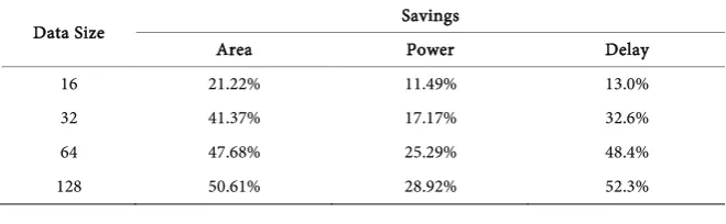
How-ever, this design has two major problems: one, it just creates up to Sd values for a given tag position; the tag can only be shuffled and hidden in this value space; and two, the cost of the rotation increases exponentially with the data size. To see how small block rotation helps to reduce the design cost, we imple-mented the designs for 16-, 32-, 64-, and 128-bit data rotations based on 8-bit blocks. Table 1 shows the related savings on the area, power, and execution de-lay as compared to the related full data rotation designs. As can be seen from the experiments, the savings from the small-block-based designs are significant.
[image:10.595.209.539.631.733.2]Therefore, here we propose to rotate the data on small blocks such that a large shuffle space can be created and, at the same time, the rotation cost can also be reduced.
Table 1. Cost saving of block based design over full rotation designs.
Data Size Savings
Area Power Delay
16 21.22% 11.49% 13.0%
32 41.37% 17.17% 32.6%
64 47.68% 25.29% 48.4%
DOI: 10.4236/jcc.2018.61015 145 Journal of Computer and Communications
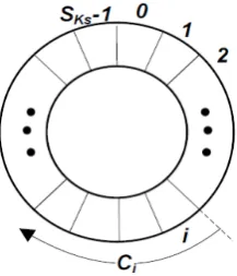
Assume the block size is Sb, we divide the data field into n S S= d/ b blocks. The rotation of each block requires logSb control bits. Given key Ks, we can extract SKs random control values from the bit stream ring formed be Ks, as demonstrated in Figure 6, where the last key bit is adjacent to the first bit. A control value Ci is a bit segment starting from bit i in the ring. We, then, group the n blocks into SKs groups of a similar size. The data field size may not be a multiple of the block size. In this case, the smaller block of the size less than Sb will form a separate group. A bit segment ( , , ,C C0 1 CSKs−1) from the control
ring is selected to control block rotation in a group.
As a demonstration, Figure 7(a) shows a design for 108-bit data with a block size of 8 bits and the control of 7 bits (that is used in our experiment). The data field is divided into 14 blocks ( , , , )b b1 2 b14 with the last block of 4 bits, which are then partitioned into 7 groups. Three bits control the rotation of each group. Figure 7(b) shows blocks (b1 and b2) in the first group are rotate-left shifted 1bit when the control value for the group is 001 (C0=001).
The block based design allows the tag bits to be concealed by up to SKs
b
S
val-ues, larger than the space (up to 2SKs values) provided by the design with the
[image:11.595.321.430.355.482.2]full range rotation.
Figure 6. Control bit ring for data field shuffle.
[image:11.595.260.491.509.694.2]DOI: 10.4236/jcc.2018.61015 146 Journal of Computer and Communications
5. Experimental Evaluation and Results
To evaluate our design, we built a simulation platform, as shown in Figure 8. We use the 2D-mesh NoC model developed by [25] as our baseline NoC. Each router in the network performs five basic operations: link traversal (LT) to transfer a packet from the output of one router to the input of another router, buffer write (BW) to save incoming packets, routing computation (RC) to de-termine the switching direction for a packet, switch allocation (SA) to arbitrate multiple packet switching in the router, and switching traversal (ST) to move a packet from the incoming buffer to the router’s output.
The five operations are pipelined into 3 stages. In addition, the XY routing algorithm, the wormhole switching scheme and the matrix arbitration, com-monly used in the NoC designs, are also implemented in the baseline model.
A cycle-accurate NoC simulator, Booksim 2.0 [26], is used to run application traces collected by Netrace 1.0 [27]. We modify the simulator to simulate the Trojan attack and the attack detection over the NoC for each application.
The hardware models are synthesized with Synopsys Design Compiler [28] based on the TSMCs 65 nm cell library [29] for cost estimation. The experiment results are presented below.
5.1. Determining Packet Label Size
With our design, we first need to decide the packet label size. In our experi-ments, we use 8x8-mesh network with the packet size of 128 bits. The packet source and destination addresses each require 6 bits so the tag size is 6 6 12+ = bits.
[image:12.595.252.494.556.706.2]We run the application traces with Booksim to simulate their network per-formance on the given NoC. Table 2 shows the average packet latency in terms of clock cycles (cc) and the traffic injection rate in packets per clock cycle (ppc), for each application. Based on Equation (4), we find the label size, as shown in the last column in the table. For the set of applications, we choose the largest size (namely, 8 bits) in our designs for the Trojan and packet hijacking detection unit.
DOI: 10.4236/jcc.2018.61015 147 Journal of Computer and Communications Table 2. Average injection rate, latency and packet label size.
Applications (abbr.) Injection Rate (ppc) Latency (cc) SLp (bits)
Blackscholes (blks) 0.015192 31.3914 5
Bodytrack (bdyt) 0.084288 37.5532 8
Canneal (canl) 0.016099 32.3142 5
Dedup (dup) 0.079224 32.5551 7
Fluidanimate (flud) 0.018139 33.0537 5
Swaptions (swap) 0.176881 30.6503 8
Vips (vps) 0.061652 33.3856 7
X264 0.009839 32.2271 4
5.2. Costs of Hardware Trojan
We implement two Trojans (HT1 and HT2) that have following functionality and capability in playing with packet tags:
• HT1: using randomly guessed tag value and bit positions during an attack.
• HT2: working with the software accomplice in an attempt to uncover the tag
bit positions before hijacking takes place. To do that, the software accomplice repeatedly sends a constant data to the Trojan. By comparing the received packets from the accomplice, the Trojan may be able to identify some tag bit positions.
The area, power and delay overheads of the two hardware Trojans are given in Columns 3 & 5 in Table 3. The relative values in percentage (labelled r) as com-pared the costs of a baseline router (see Column 2, where the delay is the longest path delay, which determines the clock cycle time) are also given in the table. The two Trojans consume less than 3% area and 0.4% power of the single router, and incur less than one clock cycle delay (27% of the router’s clock cycle time). Figure 9 shows the area and power consumption of each Trojan relative to the NoC size. For a single Trojan inserted in a large network of many nodes, the overheads become ignorable. With our 8 × 8-mesh network, the footprints of HT1 and HT2 are, respectively, just 0.024% and 0.043% of the overall NoC. The performance overhead may also very unlikely be detected at the circuit testing stage without knowing how to activate the Trojan.
5.3. Security Evaluation
We evaluate the security of our design in terms of the detection rate. To see the effectiveness of our tag bit scrambling, we also investigate the attack success rate and the data invalid rate. The average data invalid rate, detection rate and attack success rate under two detection designs (with and without tag bit scrambling) are given in Table 4.
DOI: 10.4236/jcc.2018.61015 148 Journal of Computer and Communications
[image:14.595.211.534.74.224.2] [image:14.595.208.541.273.347.2](a) (b)
Figure 9.Trojan overhead vs network size.
Table 3. Overheads of HT1 and HT2.
Metric Baseline Router HT1 HT2
r (%) r (%)
Area (um2) 83962 1313 1.56 2362 2.81
Power (uW) 53920 136 0.25 187 0.35
[image:14.595.208.540.382.453.2]Delay (ns) 0.56 0.07 12.5 0.15 26.8
Table 4. Security evaluation against HT1 and HT2 attacks.
Metric without scrambling with scrambling
HT1 HT2 HT1 HT2
Data Invalid rate (%) 99.3509 0 99.3857 98.9684
Detection rate (%) 99.9846 99.9740 99.9870 99.9753
Attack success rate (%) 0.0006 0.0260 0.0005 0.0009
be seen that the success rate is not exactly the complement of the detection rate. If an attack has escaped the authentication but the data of the hijacked packet has been altered, the attack cannot be successful. However, if the HT2 Trojan is used, the data invalid rate is reduced to 0, as shown in Column 3 in the table. This is because the HT2 Trojan can identify the static tag bit positions and alter the tag on the correct bits in the data field. We also observe that with HT2, the attack success rate is increased and accordingly the attack detection rate is re-duced due to the increased tag collision frequency. But if the mixed tag and data field is dynamically scrambled, the security of the design is greatly improved, as shown in the last two columns in the table, where 99.9% attacks can be detected and for the rest of attacks that have gone undetected, a majority of them are still unsuccessful due to the invalid data they contain. Most importantly, the low at-tack success rate (0.0005% from HT1and 0.0009% from HT2) is accompanied with a high data invalid rate (99.38% from HT1 and 98.96% from HT2).
5.4. Overhead of Detection Unit
ob-DOI: 10.4236/jcc.2018.61015 149 Journal of Computer and Communications
tained in Section 5.1., the remaining 108-bit data field in the 128-bit packet will be used for data and tag. Therefore, the key size is 20 bits (the sum of the address size and Lp size). The design shown in Figure 5(b) is used for key generation
and the design given in Figure 7 (based on the 8-bit Barrel Shifter) is applied for data field scrambling in our experiments.
To see how effective is the cost saving on the reduced LUT and block-based scrambling, we investigate the design with full LUT (see Figure 3(a)) and with full data field scrambling. The relative costs as compared to the baseline router design for the three designs are given in Columns 2 - 4 of Table 5. As can be seen from the table, our DU design incurs very small overheads, 3.37% on area and 2.61% on power. However, without the LUT reduction, the costs would be very high (increased to 76.90% and 77.86% in the area and power); the costs would also be higher if the block-based scrambling is not used.
For the performance overhead, we first measure the delay of DU with Synop-sys Design Compiler. The delays are then incorporated into the BookSim simu-lation, based on which we obtain the execution time for each application. Figure 10 shows the normalized execution time with and without the detection unit; on average, only 0.097% (as given in the rightmost group, AVG) execution delay is incurred.
6. Conclusions
[image:15.595.209.537.482.620.2]In this paper, we proposed a tag-based authentication design to detect the packet hijacking by a hardware Trojan that is embedded in a third-party NoC. Our de-sign incorporates two customization techniques: one, the packet tagging and authentication that are tailored to the packet hijacking attack, with the tag mixed in the packet data so that the tag bit positions are hard to be identified by the
[image:15.595.209.541.669.718.2]Figure 10. Normalized execution time.
Table 5. Area and power overheads of DU.
Metric With full LUT rel. (%) With full scram (%) DU rel (%)
Area (um2) 76.90 5.08 3.37
DOI: 10.4236/jcc.2018.61015 150 Journal of Computer and Communications
attacker; and two, the tag size is determined by the NoC size and the packet label size is customized to the applications so that the packet space consumption in-curred by the detection is reduced. To further reduce the design overhead, we introduced a lookup table based design for dynamic-tag generation and a block based data field rotation for tag scrambling. Our experiments on an 8 × 8-mesh network show that the detection unit incurs about 3.37% area, 2.61% power, and 0.097% performance overhead as compared to the baseline design.
It must be pointed out that like other security designs, our design, especially the tag bit position, can be cracked by an exhaustive brute-force search. How-ever, the brute-force search often requires large computing and storage supports. Our proposed scheme targets the small Trojan that lacks sufficient resources for such an expensive search and its software accomplice also has no opportunities to decode the packet tag since the detection unit has filtered out the tagging in-formation for each packet before it reaches to the destination software.
References
[1] Olukotun, K., Nayfeh, B.A., Hammond, L., Wilson, K. and Chang, K. (1996) The Case for a Single-Chip Multiprocessor. ACM Sigplan Notices, 31, 2-11.
https://doi.org/10.1145/248209.237140
[2] Maeurer, T.R. and Shippy, D. (2005) Introduction to the Cell Multiprocessor. IBM Journal of Research and Development, 49, 589-604.
https://doi.org/10.1147/rd.494.0589
[3] Bhunia, S., Hsiao, M.S., Banga, M. and Narasimhan, S. (2014) Hardware Trojan At-tacks: Threat Analysis and Countermeasures. Proceedings of the IEEE, 102, 1229-1247.https://doi.org/10.1109/JPROC.2014.2334493
[4] Tehranipoor, M. and Koushanfar, F. (2010) A Survey of Hardware Trojan Taxon-omy and Detection. IEEE Design and Test of Computers, 27, 10-25.
https://doi.org/10.1109/MDT.2010.7
[5] Agrawal, D., Baktir, S., Karakoyunlu, D., Rohatgi, P. and Sunar, B. (2007) Trojan Detection Using Ic Fingerprinting. IEEE Symposium on Security and Privacy, 296-310.https://doi.org/10.1109/SP.2007.36
[6] Jin, Y. and Makris, Y. (2008) Hardware Trojan Detection Using Path Delay Finger-print. IEEE International Workshop on Hardware-Oriented Security and Trust, HOST 2008, 51-57.
[7] Diguet, J.-P., Evain, S., Vaslin, R., Gogniat, G. and Juin, E. (2007) Noc-Centric Se-curity of Reconfigurable Soc. Proceedings of the 1st International Symposium on Networks-on-Chip, 223-232.
[8] Fiorin, L., Palermo, G., Lukovic, S., Catalano, V. and Silvano, C. (2008) Secure Memory Accesses on Networks-on-Chip. IEEE Transactions on Computers, 57, 1216-1229.https://doi.org/10.1109/TC.2008.69
[9] Porquet, J., Greiner, A. and Schwarz, C. (2011) Noc-Mpu: A Secure Architecture for Flexible Co-Hosting on Shared Memory Mpsocs. IEEE Design, Automation & Test in Europe, 1-4.https://doi.org/10.1109/DATE.2011.5763291
DOI: 10.4236/jcc.2018.61015 151 Journal of Computer and Communications [11] Wassel, H.M.G., Gao, Y., Oberg, J.K., Huffmire, T., Kastner, R., Chong, F.T. and Sherwood, T. (2014) Networks on Chip with Provable Security Properties. IEEE Micro, 34, 57-68.https://doi.org/10.1109/MM.2014.46
[12] SonicsMX Smart Interconnect Datasheet. http://www.sonicsinc.com
[13] Alves, T. and Felton, D. (2004) Trustzone: Integrated Hardware and Software Secu-rity. ARM White Paper, 3.
[14] Baron, S., Wangham, M.S. and Zeferino, C.A. (2013) Security Mechanisms to Im-prove the Availability of a Network-on-Chip. IEEE International Conference on Electronics, Circuits, and Systems, 609-612.
[15] Yu, Q. and Frey, J. (2013) Exploiting Error Control Approaches for Hardware Tro-jans on Network-on-Chip Links. IEEE International Symposium on Defect and Fault Tolerance in VLSI and Nanotechnology Systems (DFTS), 266-271.
[16] Boraten, T. and Kodi, A.K. (2016) Packet Security with Path Sensitization for Nocs.
IEEE Design, Automation & Test in Europe, 1136-1139.
https://doi.org/10.3850/9783981537079_0180
[17] Rajesh, J.S., Ancajas, D.M., Chakraborty, K. and Roy, S. (2015) Runtime Detection of a Bandwidth Denial Attack from a Rogue Network-on-Chip. Proceedings of the
9th International Symposium on Networks-on-Chip, 8.
[18] Ancajas, D.M., Chakraborty, K. and Roy, S. (2014) Fort-Nocs: Mitigating the Threat of a Compromised Noc. Proceedings of the 51st Annual Design Automation Con-ference, 1-6.https://doi.org/10.1145/2593069.2593144
[19] Peterson, W.W. and Brown, D.T. (1961) Cyclic Codes for Error Detection. Pro-ceedings of the IRE, 228-235.https://doi.org/10.1109/JRPROC.1961.287814
[20] Bellare, M., Canetti, R. and Krawczyk, H. (1996) Keying Hash Functions for Mes-sage Authentication. Annual International Cryptology Conference, Springer. [21] Rogers, A. and Milenkovic, A. (2009) Security Extensions for Integrity and
Confi-dentiality in Embedded Processors. Microprocess. Microsyst (Netherlands), 33, 398-414.
[22] Yan, C., Rogers, B., Englender, D., Solihin, D. and Prvulovic, M. (2006) Improving Cost, Performance, and Security of Memory Encryption and Authentication. 33rd Int. Symposium on Computer Architecture.
https://doi.org/10.1145/1150019.1136502
[23] Hong, M., Guo, H. and Hu, S.X. (2012) A Cost-Effective Tag Design for Memory Data Authentication in Embedded Systems. Proceedings of the 2012 International Conference on Compilers, Architectures and Synthesis for Embedded Systems
(CASES 2012), 17-26.https://doi.org/10.1145/2380403.2380414
[24] Elbaz, R., Torres, L., Sassatelli, G., Guillemin, P., Bardouillet, M. and Martinez, A. (2010) Block-Level Added Redundancy Explicit Authentication for Parallelized En-cryption and Integrity Checking of Processor-Memory Transactions. Transactions on Computational Science X. Special Issue on Security in Computing, Part I, 6340, 231-260.
[25] Bokhari, H., Javaid, H., Shafique, M., Henkel, J. and Parameswaran, S. (2015) Su-pernet: Multimode Interconnect Architecture for Manycore Chips. Proceedings of the 52nd Annual Design Automation Conference, 85.
https://doi.org/10.1145/2744769.2744912
[26] Jiang, N., Balfour, J., Becker, D.U., Towles, B., Dally, W.J., Michelogiannakis, G. and Kim, J. (2013) A Detailed and Flexible Cycle-Accurate Network-on-Chip Simulator.
DOI: 10.4236/jcc.2018.61015 152 Journal of Computer and Communications 86-96.https://doi.org/10.1109/ISPASS.2013.6557149
[27] Hestness, J. and Keckler, S.W. (2011) Netrace: Dependency-Tracking Traces for Ef-ficient Network-on-Chip Experimentation. The University of Texas at Austin, Dept. of Computer Science, Tech. Rep.
[28] Synopsys Design Compiler. http://www.synopsys.com. [29] TSMC 65nm GP Standard Cell Libraries-tcbn65gplus.