© 2017 IJSRST | Volume 3 | Issue 7 | Print ISSN: 2395-6011 | Online ISSN: 2395-602X Themed Section: Science and Technology
Implementation of Quasi-Z-Source Four-Leg Inverter with PV by using Model
Predictive Control Scheme
Midde Venkata Ramaiah, B. Thejasvi
Department of Electrical and Electronics Engineering, Jawaharlal Nehru Technological University, Anantapur, Anantapur, Andhra Pradesh, India
ABSTRACT
The Implementation of Quasi-Z-Source Four-Leg Inverter with PV by using Model Predictive Control Scheme is proposed in this paper. In order to reduce the drawbacks of traditional three phase voltage source inverter (VSI). Photovoltaic (PV) is a term which converts the light into electricity. This topology features a wide range of voltage gain which is suitable for applications in renewable energy-based power systems, where the output of the renewable energy sources varies widely with operating conditions such as wind speed, solar irradiation and temperature. To improve the capability of the controller, an MPC scheme is used which implements a discrete-time model of the system. The controller handles each phase current independently, which adds flexibility to the system. The performance of quasi z source three-phase four-leg VSI with PV by using model predictive control (MPC) was simulated using MATLAB Simulink under balanced and unbalanced load conditions as well as single-phase open-circuit fault condition.
Keywords : DC–AC power conversion, four-leg inverter, PV array, model predictive control (MPC), quasi-Z-source inverter (QZSI).
I.
INTRODUCTION
Now a days the demand of conventional energy sources increasing, in order to reduce this demand an alternative energy sources that’s why renewable energy sources can be used. Renewable energy sources are wide spread, freely accessible, less maintenance, less the cost of operation and no impact on environment. Due to above advantages of renewable energy sources are used in various applications such as distributed generation, power unavailable areas, off grid and emergency situation.
However renewable energy can be converted into electrical distribution systems need power electronic converters. The performance of all these RES thus depends on the power electronic converters and control method [1].In most of applications to supply the power to either the local loads or the grid a three-phase voltage-source inverters are used. But it has two disvantages they are 1) variation of input voltage and 2) output unbalanced current.
The variation of this input voltage due to random and sporadic nature of RES this is first disvantages of disadvantage of VSI .The VSI must have input voltage is
greater than the maximum value of the line to line output voltage in order to vouch reliable and continuous power for the loads, which is a major dispute in such systems. To overcome this drawback a dc - dc chopper is used at the input stage to supply the regulated voltage for the voltage source inverter. However, by using this chopper circuit engrossment increases and require multi loop control structure which makes high cost and lower reliability.
converter main circuit to the power source, load for
providing unique features that cannot be observed
in the traditional VSI and CSI source converters
. This is the simple L–C network to achieved buck–boost functionality in single-stage power conversion.The three-phase VSI are usually designed for balanced three-phase loads, this is the second disadvantage of VSI. However, in distribution power generation system unbalanced load conditions are common where power is delivered to local loads. Due to these unbalanced loads current circulating flow in power system Causing swelter of the neutral line and harmonic distortion on the output voltage [8], [9]. One way to relieve this problem a three-phase four-leg VSI is used. This network can produce for even nonlinear and unbalanced loads three-phase balanced output. This is the best method for UPS systems and individual power generation systems.
The reliable and efficient operation of the renewable energy-based power generation systems depends on the control scheme of the power converter which plays a important role. There are a number of proposed control strategies for the QZSI. In most applications, proportional integral (PI) controller is used to control current, voltage, etc. but it has some drawbacks. The major drawback is entire system performance depends on the inner control loop performance. To generate PWM signals for the power switches the controller needs a modulator, such as 3-D-SVPWM to implement the desired control action.
The alternative controller for QZSI is model predictive control (MPC) which is having wild vigorous response, simple concept, and capacity to include different non linearity’s and limitations. The major advantage of MPC is without using modulation stage a direct control action to the converters. In most of applications MPC is used in multilevel inverters, traditional three-phase inverter, and a number of electrical drives for current control.
In these presents Implementation of Quasi-Z-Source Four-Leg Inverter with Model Predictive Control Scheme for Renewable Energy Based Power Systems. The assistances of this study are shortened as monitors.
1. To minimize the drawbacks of three phase traditional VSI and two-stage power conversion by using the QZS network instead of a dc–dc + dc–ac converter.
2. The reliable operation of renewable energy-based power system under balanced and unbalanced load conditions using three-phase four-leg inverter. 3. The control of load current and QZS network
capacitor voltage using MPC scheme with high precision and wild response.
4. The proposed MPC controller knobs apiece phase current independently. Due to this QZS four-leg inverter offers fault-tolerant capability.
II.
MODEL OF QZS FOUR LEG INVERTER WITH
PV
2.1 Topology
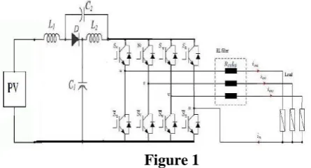
The QZS four-leg inverter with R–L filter connect to PV input as shown in Fig.1. This topology can be explored as three parts: 1) Photo voltaic source 2) QZS network and 3) four-leg inverter with R–L filter and load. In the first part of this topology Photovoltaic (PV) is a term which converts the light into electricity. In the second stage of this topology the QZS is made of LC network in the shoot through state both devices are gated at the same time. .During this state, energy can be transferred from the capacitors to the inductors in QZS network.
In the third part of this topology, the four-leg VSI inverter is used. As shown in Fig. 1, the neutral load point is connected to the mid-point of the VSI inverter’s fourth phase leg to tolerate for zero voltage or current sequence. But it has one major drawback is switching organizations are more complicated compared to a three phase three leg VSI due to extra fourth leg. By using an extra fourth leg to improve the VSI inverter ability, consistency and also it is operated under balanced or unbalanced or linear or nonlinear load conditions.
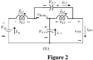
2.2 Mathematical analysis of the QZS Network with PV
The QZS network of equivalent circuits as shown in Fig. 2(a) and 2(b), respectively [33] in this analysis PV consider as dc voltage source. When it is operated in shoot through state and non-shoot-through states .In this figures all voltages and currents are shown with arrows and the polarities.
2.2.1 Non shoot-through state
The four-leg inverter network is represented by a constant current source when it is operated during non-shoot through state as shown in below fig 2(a).
By applying in above Fig. 2(a) Kirchhoff’s voltage law (KVL), voltage of inductors (VL1 and VL2), dc-link voltage (VPN), and diode voltage (Vdiode) are written as …… (1)
…. (2)
2.2.2 Shoot-through state
The four-leg inverter network is represented by short-circuit, when it is operated during shoot through state as shown in below fig 2(b).
Figure 2
By applying in above Fig. 2(a) Kirchhoff’s voltage law (KVL), voltage of inductors (VL1 and VL2), dc-link voltage (VPN), and diode voltage (Vdiode) are written as
… (3) ... (4)
The network operated at steady state over one switching cycle, the average capacitor voltages are
... (5)
Where T0 is the shoot-through state period, T1 is the non-shoot-through state period, and Vin is the input dc voltage.
From (2), (4), and (5), equations the peak dc-link voltage across the inverter bridge in Fig. 1 is
… (6)
Where B is the boost factor of the QZSI, and T is the switching cycle (T0 + T1). The average inductor currents L1 and L2 are
……….. . (7)
Applying Kirchhoff’s current law (KCL) in above figures and (7) results in
……… (8)
From above all equations voltage gain (G) of the QZSI can be expressed as
̂
.. (9)
Where M is the modulation index and is the peak phase voltage
2.3 Mathematical analysis of the Four-Leg Inverter The four-leg inverter with the output R–L filter equivalent circuit as shown in Fig. 3
Figure 3
Where the Lfj is the filter inductance, Rfj is the filter resistance, and Rj is the load resistance for each of the phase j = a, b, c.
corresponding phase and line voltages are presented in [34].In addition to fourth leg one more switching state is needed in order to operate in shoot through state. Therefore in this application a total number of 17 switching states are used.
The four-leg inverter of each leg voltage can be expressed as
.. (10)
Where Sa, Sb, Sc, and Sn are the switching states of four-leg inverter , Vdc dc link voltage, and VnN load neutral voltage.
The inverter output voltage can be expressed in terms of the previous voltages of inverter
…… (11)
The voltages of inverter can be stated in terms of load-neutral voltages and currents by applying Kirchhoff’s voltage law (KVL) to Fig. 3
( )
( )
( ) ….. (12)
From equations (11) and (12), the output voltages can be
written as ( )
( )
( ) …… (13) Equation (13) can be simplified to
( ) ……… (14) An the neutral load current in can be written as …… (15)
From equation (14) the output current can be expression as
-( ) ] .. (16)
III.
PROPOSED MPC
The block diagram of the proposed MPC scheme is shown fig 4 .It is mainly divided into two layers: 1) a predictive model and 2) cost function optimization. To predict future behavior of the control variables using discrete-time model of the system. To minimize the error between the reference and the predicted control
variables used the cost function in the next sampling time .This MPC control technique has many advantages are to implement for both linear and nonlinear systems, high precision and wild dynamic response [35].
Figure 4
3.1 predictive model: This is used to estimate the future behavior of each of the output currents (ia, ib, ic). By substituting equation (18) into (16) the each output phase current in
Discrete time model is
… (19) Where ij(k + 1) is the predicted output current at the next sampling time and Av and Ai are constants are defined by
….. (20)
The continuous capacitor current can be stated as
………… (21)
Where C1 is the capacitance, rc is the equivalent series resistance (ESR) of the capacitor from equation (21) the capacitor voltage is
……… (22)
By substituting equation (18) into (22), the VC1 can be written as
…… (23)
Where VC1 (k + 1) is the capacitor voltage at the next sampling time and iC1 (k) is capacitor current. The capacitor current during non shoot-through state can be defined as
…….. (24)
And shoot-through state can be defined as ……… (25)
3.2 optimization of Cost function
two cost functions they are 1) to reduce the output current error and 2) capacitor voltage error in the next sampling time. The cost function of output current is defined as
( ) (
) +( ) (
) .. (26)
Where is the output reference current, ij(k + 1) is the output predicted current vector in the next step (j = a, b, c).
The capacitor voltage in cost function can be defined as | | …… (27)
Where is the reference capacitor voltage and is the predicted capacitor voltages. The overall cost function is ……. (28)
Figure 5. Proposed MPC algorithm Flowchart for QZS four-leg inverters
3.3 Control algorithm
The proposed control algorithm of flowchart is shown in Fig. 5. The Cost function minimization is executed for each voltage vector to predict the values reaped, calculate the cost function, and store the very low value and the index value of the corresponding each switching state. The control algorithm of proposed system can be concise in steps.
1) Sampling the phase output currents (iabc), inductor current (iL1), and capacitor voltage (VC1).
2) The above parameters are used to output predict currents and capacitor voltage using the predictive model of proposed system 3.1, and 3.2, respectively. 3) Calculate all predictions using complete cost
function.
4) The minimum voltage vector corresponds to the optimal switching state that reduces the cost function is designated to be applied at the next sampling state.
IV.
Simulation results of proposed MPC
technique of QZS four-leg inverter
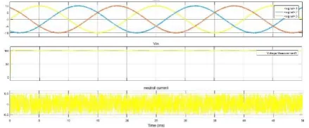
4.1 steady state analysis
The QZS network reference capacitor voltage ( ) is set to 150 V and input voltage is 100 V to perform the steady-state analysis. The following two cases are considered to show the effectiveness of the proposed controller under steady-state operation.
1) Case-1: Balanced reference currents ( = = = 10 A) and balanced loads (Ra = Rb = Rc = 7.5Ω). 2) Case-2: Unbalanced reference currents ( = 10 A,
= 5 A, = 5 A) and balanced loads (Ra = Rb = Rc = 10Ω).
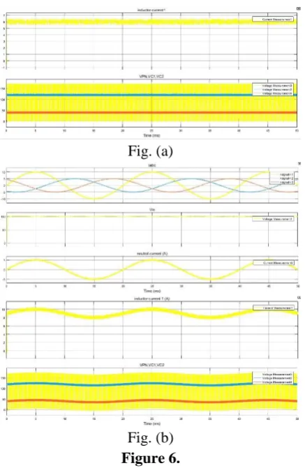
Fig. (a)
Fig. (b) Figure 6.
4.2 Transient-state analysis
To perform the transient-state analysis the reference output currents step from 5 to 10 A are shown in Fig. (a). For this test, reference loads (Ra = Rb = Rc = 6Ω) are balanced. It can be seen that the output currents track to the references with fast rise time and no overshoot. In Fig. (b), the results are presented with unbalanced reference current step change and balanced loads (Ra = Rb = Rc = 6Ω). For this test, all reference output currents are set to 5 A at the beginning. Then, reference currents are set to = 7A, = 10A, and = 12A. Results of this test show that the proposed controller handles each phase current independently and the output currents (ia, ib, ic) and the capacitor voltage (VC1) track their references and the dc-link voltage (VPN) is kept constant. However, the double line frequency (2*fo) ripple exist on the QZS network due to unbalanced current. The simulation results of transient-state analysis with balanced and unbalanced reference currents are shown in Fig. (a) and (b), respectively.
Fig (a)
Fig (b) Figure 7.
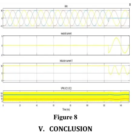
4.3 Analysis of Fault-Tolerant Capability
Figure 8
V.
CONCLUSION
This paper has proposed the Implementation of Quasi-Z-Source Four-Leg Inverter with PV by using Model Predictive Control Scheme. The main aim of this paper is to achieve single-stage power converter topology for photo voltaic system under balanced and unbalanced conditions with high control capability. To do that, QZS three-phase four-leg inverter topology was proposed in this study. To improve control capability of the controller, the MPC scheme was employed in the controller stage. The performance of the proposed inverter topology and its control strategy was simulated. The results show that the proposed technique not only has an excellent steady-state and transient performances, but also it is robust against fault conditions.
VI.
REFERENCES
[1]. "Sertac bahyhan,haitham abu- rub,Robert S.blog "MODEL PREDICTIVE CONTROL OF QUASI-Z-SOURCE FOUR-LEG INVERTER," IEEE Trans. Ind. Electron., vol. 83, no. 7, pp. 6003-6007, july. 2016.
[2]. X. Guo, D. Xu, and B. Wu, "Four-leg current-source inverter with a new space vector modulation for common-mode voltage suppression," IEEE Trans. Ind. Electron., vol. 62, no. 10, pp. 6003-6007, Oct. 2015.
[3]. F. Z. Peng, "Z-source inverter," IEEE Trans. Ind. Appl., vol. 39, no. 2, pp. 504-510, Mar./Apr. 2003. [4]. S. Kouro, J. Leon, D. Vinnikov, and L. Franquelo,
"Grid-connected photovoltaic systems: An overview of recent research and emerging PV
converter technology," IEEE Ind. Electron. Mag., vol. 9, no. 1, pp. 47-61, Mar. 2015.
[5]. Y. Li, S. Jiang, J. Cintron-Rivera, and F. Z. Peng, "Modeling and control of quasi-Z-source inverter for distributed generation applications," IEEE Trans. Ind. Electron., vol. 60, no. 4, pp. 1532-1541, Apr. 2013.
[6]. B. Ge et al., "An energy-stored quasi-Z-source inverter for application to photovoltaic power system," IEEE Trans. Ind. Electron., vol. 60, no. 10, pp. 4468-4481, Oct. 2013.
[7]. W. Qian, F. Z. Peng, and H. Cha, "Trans-Z-source inverters," IEEE Trans. Power Electron., vol. 26, no. 12, pp. 3453-3463, Dec. 2011.
[8]. H. Jin, X. Rui, Z. Yunping, W. Zhi, and S. Haixia, "The study of SPWM control strategy to reduce common-mode interferences in threephase four-leg inverters," in Proc. 3rd IEEE Conf. Ind. Electron. Appl. (ICIEA’08), Jun. 2008, pp. 924-928.
[9]. S. Bifaretti, A. Lidozzi, L. Solero, and F. Crescimbini, "Comparison of modulation techniques for active split dc-bus three-phase four-leg inverters," in Proc. IEEE Energy Convers. Congr. Expo. (ECCE), Sep. 2014, pp. 5631-5638. [10]. E. Demirkutlu and A. Hava, "A scalar resonant-filter-bank-based outputvoltage control method and a scalar minimum-switching-loss discontinuous PWM method for the four-leg-inverter-based three-phase four-wire power supply," IEEE Trans. Ind. Electron., vol. 45, no. 3, pp. 982-991, May 2009.
[11]. Y. Liu, B. Ge, H. Abu-Rub, and F. Z. Peng, "An effective control method for three-phase quasi-Z-source cascaded multilevel inverter based grid-tie photovoltaic power system," IEEE Trans. Ind. Electron., vol. 61, no. 12, pp. 6794-6802, Dec. 2014.
[12]. L. Yushan, G. Baoming, H. Abu-Rub, and Z. P. Fang, "Modelling and controller design of quasi-Z-source inverter with battery-based photovoltaic power system," IET Power Electron., vol. 7, no. 7, pp. 1665-1674, Jul. 2014.
[14]. H. Abu-Rub, A. Iqbal, S. Moin Ahmed, F. Peng, Y. Li, and G. Baoming, "Quasi-Z-source inverter-based photovoltaic generation system with maximum power tracking control using ANFIS," IEEE Trans. Sustain. Energy, vol. 4, no. 1, pp. 11-20, Jan. 2013.
[15]. I. Roasto, D. Vinnikov, J. Zakis, and O. Husev, "New shoot-through control methods for qZSI-based dc/dc converters," IEEE Trans. Ind. Electron., vol. 9, no. 2, pp. 640-647, May 2013. [16]. Y. Liu, B. Ge, F. Ferreira, A. de Almeida, and H.
Abu-Rub, "Modeling and SVPWM control of quasi-Z-source inverter," in Proc. 11th Int. Conf. Elect. Power Quality Utilisation (EPQU), 2011, pp. 1-7.
[17]. Y. Liu, H. Abu-Rub, B. Ge, F. Blaabjerg, O. Ellabban, and P. Loh, Impedance Source Power Electronic Converters. Hoboken, NJ, USA: Wiley, 2016.
[18]. X. Li, Z. Deng, Z. Chen, and Q. Fei, "Analysis and simplification of threedimensional space vector PWM for three-phase four-leg inverters," IEEE Trans. Ind. Electron., vol. 58, no. 2, pp. 450-464, Feb. 2011.
[19]. D. Patel, R. Sawant, and M. Chandorkar, "Three-dimensional flux vector modulation of four-leg sine-wave output inverters," IEEE Trans. Ind. Electron., vol. 57, no. 4, pp. 1261-1269, Apr. 2010.
[20]. D.-K. Choi and K.-B. Lee, "Dynamic performance improvement of ac/dc converter using model predictive direct power control with finite control set," IEEE Trans. Ind. Electron., vol. 62, no. 2, pp. 757-767, Feb. 2015.
About Authors:
Mr. M.Venkata Ramaiah completed B.Tech in EEE from G.Pulla Reddy Engineering College, Kurnool in 2014. He is currently doing M Tech in JNTUA college of Engineering, Anantapuram. His areas of interests are Power Electronics and Control Systems.