96
Evaluation Of Aluminum Alloy Brake Drum For
Automobile Application
Sourav Das, Ameenur Rehman Siddiqui, Vishvendra Bartaria
Abstract: The aim of the present paper is to study the braking performance of Al-Si alloys (ADC12 & LM30) brake drums using a brake drum dynamometer test rig. The braking performance of the ADC12 and LM30 alloys is evaluated on the basis of experimental parameters such as coefficient of friction, rise in temperature, braking torque, rotational speed etc. The coefficient of friction as against the normal brake liners is evaluated. The rise in temperature at the inner surface, during the braking action, has been presented. The results indicated that rise in temperature of brake drum is in the range of 40-50oC in both the alloys. The coefficient of friction was found to be in the range of 0.35-0.42 in both the Al alloys. It was observed that brake force and speed of the drum do not have any appreciable effect on the friction coefficient. Stopping distance after applying the brake was also calculated and it was observed that stopping distance reduces as a function of brake force. At a brake force of 20 N, the efficiency is increased to 80-85 %. It concludes that LM30 alloy performs better than ADC 12.
Keywords: Al alloy Brake drums, dynamometer, coefficient of friction, braking efficiency, temperature rise. ————————————————————
I. INTRODUCTION
A brake is a mechanical device which is used to absorb the energy possessed by a moving system or mechanism by means of friction. The primary purpose of the brake is to slow down or completely stop the motion of a moving system, such as a rotating disc/drum, machine or vehicle. Many aspects of slowing and stopping a vehicle are controlled by simple physics dealing with the deceleration of a body in motion [1]. The simplest way to stop a vehicle is to convert the kinetic energy into heat energy [2]. Excessive temperature can prematurely or permanently damage the lining. Burnishing operation before any final performance testing of the brake is the only desired accepted method to evaluate the brake performance. Burnishing by multiple stops on a brake simulator or on test track sets the liner for more than 85 % pad contact with the disc surface [3]. Recently Rehman et al. [4] have reported the analysis of brake drum made of Aluminum alloy–Silicon Carbide MMC (Al–SiC MMC) and compared with cast iron (CI) brake drum using a brake drum dynamometer test rig. Al–SiC MMC was reinforced with 10% and 15% SiC particle by weight. The effect of heat treatment of the Al–SiC MMC brake drum was also studied. Performance was evaluated on the basis of brake drum coefficient of friction (μ). Scanning electron microscope was used to study the effect of braking on the sliding surface of the brake drum.
Yu Zhao et.al [5] have studied the frictional wear resistance and thermal fatigue resistance of brake drums and two kinds of biomimetic coupling materials are prepared by laser surface melting and laser coating technology respectively. These materials are all compounded by base metal and biomimetic coupling units, and have different coupling characteristics, such as the variation of the unit shape, different microstructures and hardness, different chemical compositions of units. The frictional wear resistance and thermal fatigue resistance of biomimetic coupling materials and gray cast iron used for brake drum are compared. The results indicate that frictional wear resistance and thermal fatigue resistance of biomimetic coupling sample is better than that of untreated sample, and among the biomimetic samples, laser coating treated sample has superior resistance to wear and thermal fatigue comparing with laser melting treated sample. Singh and coworkers [6] have studied the failures of brake drums components during high ‗g‘ braking on spoke wheels of a motorcycle. The brake drum and the panel were found to have seized during high speed brake applications. Excessive wear on the drum liner made of cast iron was also observed. Metallurgical analysis (chemical analysis, hardness test and microstructure analysis) of the liner revealed that excessive wear on the liner was not due to any change in material properties. An experimental testing methodology was developed to simulate these failures. For the same material, testing conditions, and design specifications of cast and spoke wheels, no failure was observed in the cast wheels. This unusual failure was further investigated using three-dimensional steady state finite element analysis (FEA) of both cast and spoke wheels. The methodology adopted for determining the thermal and structural boundary conditions have been described in detail. Energy balance methodology was employed to determine the heat flux values on the drum liner. The structural boundary conditions are determined experimentally and validated with FEA. Shaoyang Zhang and Fuping Wang [7] have studied the Al matrix composites reinforced with 30 vol.% SiCp (34 μm) new brake drum in place of the conventional cast iron brake drum. Experimental studies on the brake materials differing in amounts of zirconium silicate (0 wt%, 4 wt%, 8 wt%, and 12 wt% ZrSiO4) dry sliding against the Al-MMCs drum were performed on the Chase Machine in order to examine their effects on friction and wear performances. The test procedures include friction fade and recovery, load and _________________________________
Sourav Das, Ameenur Rehman Siddiqui, Vishvendra Bartaria
Department of Mechanical Engineering, L.N.C.T, Bhopal, India, mail id. souravds21@gmail.com
Department of Mechanical Engineering, M.A.N.I.T, Bhopal, India, mail id. manitars@gmail.com
speed sensitivities at 177 °C and 316 °C, and wear. Experimental results show that the brake material containing 8 wt% ZrSiO4 had the best wear resistance and higher friction level. The brake material containing 12 wt% ZrSiO4 had the highest friction level, but wear increased rapidly. The deterioration of the wear suggests that this brake material is unreliable in commercial applications. Gultekin et.al. [8] have studied the frictional and wear characteristics of sintered copper matrix composite brake pads against cast Al–Si/SiCp brake disc and the effects of applied load on the coefficient of friction. Tribological behavior of Cu-MMC/Al-MMC couple was studied using Pin-on-Disc tribometer. The aluminum metal matrix composite material was used as a disc, whereas the graphite reinforced copper matrix composite was used as a brake pad. Frictional surfaces were investigated using a scanning electron microscope (SEM) equipped with energy-dispersive spectroscopy (EDS). The amount of wear of both brake disc and pad cannot be measured since trace amount of material was transferred. These phenomena also proved that the brake disc and the pad have high wear resistance. The friction layer on the brake pad's worn surface was confirmed as mostly of carbon and copper oxides. Daoud, and Abou El-khair [9] have reported the effect of load range of 30–100 N and speed range of 3–12 m/s on the wear and friction behavior of sand cast brake rotor made of A359-20 vol.% SiC particle composites sliding against automobile friction material. Dry sliding frictional and wear behavior were investigated in a pin-on-disc type apparatus. Automobile friction material was used as pin, while the A359-20 vol% SiC particle composites formed the rotating disc. For comparison, the wear and friction behavior of commercially used cast iron brake rotor were studied. The results showed that the wear rate of the composite disc decreased with increasing the applied load from 30 to 50 N and increased with increasing the load from 50 to100 N. However, the wear rate of the composite disc decreased with increasing the sliding speed at all levels of load applied in the present work. For all sliding speeds, the friction coefficient of the composite disc decreased with applied load. The worn surfaces as well as wear debris were studied using scanning electron microscopy (SEM), energy dispersive X-ray (EDX) analyzer and X-ray diffraction (XRD) techniques. At load of 50 N and speed range of 3–12 m/s, the worn surface of the composite disc showed a dark adherent layer, which mostly consisted of constituents of the friction material. This layer acted as a protective coating and lubricant, resulting in an improvement in the wear resistance of the composite. Various other researchers [10-20] have studied the braking behavior of metal matrix composite materials. In the present work Al-Si alloys (ADC12 and LM30) brake drums were made by casting technique. These drum brakes were tested in a brake test rig. The brake drum was rotated at various speeds namely 700, 1000 and 1300 RPM and various brake force in the range of 0.5 N to 20 N was applied and the temperature rise (inner and outer surface), coefficient of friction, stopping distance and braking efficiency were found out. The deceleration rate of the brake drum was found out by estimating the time required to stop after applying the brake by a high speed camera.
II. METHODOLOGY
1) Materials: In the present experiment, two types of Al-Si alloys were selected. One is eutectic Al-Al-Si (ADC12) alloy which consists of Al-13.20%Si-1.79%Cu-0.87%Mg-0.76 Ni and the other one is hypereutectic (B.S.: LM30) Al-Si alloy which contains Al-17.40%Si-4.10%Cu-0.241%Mg. The chemical compositions of the alloys were found out by optical spectrometer (SPECTROMAXx). For microstructural examination samples are cut from the brake drum, mechanically polished using standard metallographic practices, etched with Keller‘s reagent and observed in Microscope.
2) Mechanical Properties: The tensile strength, yield strength and % elongation are evaluated by an Instron made Ultimate Tensile Machine at room temperature and at a strain rate of 0.01/s. The hardness of the alloys (ADC 12 & LM30) is found out by a universal hardness tester and Vickers hardness no. is reported. Young modulus was found out by a sonic modulus tester. The impact energy of the alloys was measured by an Instron make impact tester. 3) Casting of Brake drums: For making the brake drum,
ADC 12 & LM30 Al-Si alloys are melted in an electrical resistance furnace. The Al alloy melt was covered with Coveral 11 flux in order to reduce the oxidation of aluminium. Before pouring, dry nitrogen gas was purged for degassing. After degassing, the liquid alloy was cleaned. A cast iron die was used to make the brake drums. Figure 1a shows the photograph of the cast iron die for making the drums. The brake drum castings are shown in 1b
Fig. 1 (a) Cast Iron Die (b) Brakedrum castings
4) Test Rig: For brake drum testing, a setup has been designed for evaluating brake parameters. For this an A.C. motor of Kirloskar make of 3.6 KW at 1440 rpm speed is used with a variable speed drive from L&T for speed variation. A fly wheel weighing 40 Kg is used. An electromagnetic clutch is fitted for power transmission from the motor shaft to the flywheel. Figure 2 shows the photo of the complete set up containing main frame fabricated out of heavy mild Steel channel and base plate base. Test facility is fitted with bolts on main frame. The set up has the sub units such as AC Motor(1) Electromagnetic Clutch (2) Brake Torque Plate (3) Loader Pan (4) Chuck to hold the Drum (5), Gravity Brake Loader
(6), Fly wheel (7) Main Frame (MS Channel ) (8), Base Plates bolted on (9)and Load Cell(10). A high speed camera was used to record the whole process of the braking test at 2000 frame per second. This enables us to count the number of revolutions between any two given times after braking and thus it was easier to calculate the deceleration of the
98 flywheel and also the number of revolutions between
the point of application of load and the stopping point.
Fig. 2 Brake drum Test Rig
III. RESULTS
A. Microstructure of ADC12 and LM30 Al alloys
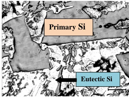
Al-Si alloy is a two phase alloy in which one phase is Al and the other one is Si. Silicon does not react with Al and nucleate separately. Al-Si alloy is a cast alloy and presence of Si enhances the fluidity and facilitates intricate shape castings. Apart from Si, the alloy has Cu, Mg and Ni as alloying elements. Cu and Mg enhance the strength of the alloy and Ni provides high temperature strength properties. Figure 3 shows a typical microstructure of Al-Si (ADC12) alloy. It shows primary Al (marked A) and eutectic silicon (marked B) around the dendrites of Al and in the interdendritic regions. It is noted from the figure that eutectic silicon is usually of needle shaped. The interdendritic arm spacing of primary Al i.e., distance between two neighboring dendrites is of the order of 20 µm. The needle shaped eutectic silicon largely hampers the tensile elongation and also the strength. Al-Si (LM30) alloy is a hypereutectic alloy has 17 wt.% Si. The microstructure of LM30 alloy consists of primary Al in dendritic morphology and eutectic Si. The primary Si in cuboid shape is also observed. Fig. 4 shows a typical microstructure of LM30 alloy. It shows primary Si cuboids, eutectic Si (needle shaped) and Al in dendritic morphology (white phase).
Fig. 3 Microstructure of ADC12 alloy
Fig. 4 Microstructure of LM30 alloy
B. Mechanical Properties:
The mechanical properties of ADC12 and LM30 alloys are shown in Table-I. The UTS of ADC12 and LM30 alloy is found 180 MPa and 165 MPa respectively. It is observed from the table that both ADC12 and LM30 alloys is brittle material having 1 % tensile elongation. The proof stress of ADC12 and LM30 alloys is found 130 MPa and 120 MPa respectively. The hardness value of ADC12 alloy is 80 HV and LM30 alloy is 125 HV. The impact energy absorption is around 1.0 Joule.
Table I
Mechanical Properties of ADC12 and LM30 alloy
Properties ADC12 LM30
Ultimate tensile strength (MPa) 180 165
Proof Stress (0.2%) (MPa) 130 120
Hardness (HV) 80 125
% Elongation ~1% ~1%
Impact energy absorption
(Joule) 1.00 1.25
Young Modulus (GPa) 78 82
C. Effect of Load on Coefficient of Friction:
Force is applied through the brake paddle to stop the vehicle. This action is taken place by the effective transmission the force through the calipers to brake shoe which touches the brake drum surface and due to high coefficient of friction between the drum materials (Al alloy) and brake shoe the vehicle stops. The deceleration rate of the wheel measures the braking efficiency. Higher the deceleration rate more would be the braking efficiency. The time for stopping the vehicle i.e., zero velocity is measured by a high speed camera. This is one of the efficient tools to find out the braking efficiency. Figures 5&6 show the coefficient of friction of the system (ADC12 and LM30 Al alloy) measured as a function of braking force at different rotational speed. It is observed that the coefficient of friction is varies in the range 0.31 to 0.40 and the average value is found around 0.357. It stems from the above fact that coefficient of friction is independent of braking force and rotational speed. In fact, it depends essentially on the surface of the braking materials.
1
7
10
5
4
A
B
Primary
Si
Fig. 5µ of ADC12 alloy Fig. 6µ of LM30 alloy
D. Effect of load on the rise in temperature:
During the application of brake to retard the vehicle, there is friction between the brake pad and drum materials. In this combination, one is metallic and other one is nonmetallic part (liner) mainly made of polymer mixed with metal powders. During braking, the friction between these materials develops temperature. The rise in temperature largely deteriorates the surface properties of both the parts. The fading behavior of the brake parts has to check while implementing new materials if the temperature rise is higher. In the present study, two experimental parameters such as brake force and speed of drum affects directly the rise in temperature. The temperature of the inner and outer surface of the Al alloy drum is measured using a lazer based temperature recorder. Figure 7 shows the rise in temperature of ADC12 alloy in the inner and outer surface at a drum speed of 1300 RPM. It is noted that the temperature in the inner surface is more than the outer surface. Fig. 8 shows the rise in temperature of LM30 alloy at a speed of 1300 RPM. It is noted that at a speed of 700 RPM, temperature of the inner surface is found in the range of 42-45 0C and towards the outer surface, it is 40-41 0C. The rise in temperature of the drum surface does not have any effect on the braking force used i.e., in the range of 5N to 20 N. At a speed of 1000 RPM, the rise in temperature in the inner surface is recorded to be in the range of 44-48 0C and in the outer surface it is 41-43 0C. Further, at a speed of 1300 RPM, the rise in temperature in the inner surface is 42-50 0C and at the outer surface it is 40-46 0C. Table II shows the rise in temperature of the inner surface of the brake drum of ADC12 and LM30 alloy at speeds of 700, 1000 and 13000 RPM.
Fig.7. Effect of load on the rise in temperature of LM30 alloy at a speed of 1300 RPM.
Fig.8. Effect of load on the rise in temperature of ADC12 alloy at a speed of 1300 RPM.
Table II
Rise in temperature of the brake drum at various speeds of ADC12 and LM30 alloy
Speed (RPM)
Temperature of Inner surface of LM30 Alloy (0C)
Temperature of Inner surface of
ADC12 Alloy (0C)
700 42-45 40-42
1000 44-48 42-49
1300 42-50 48-57
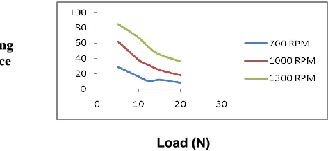
E. Effect of load on the stopping distance:
In the braking experiments, a predetermined normal load is applied on the pan which activated force on the spring loaded brake pad. The brake pad expands and touches the inner surface of the Al alloy brake drum. Due to friction force, the drum stops after some time of moving. The stopping of the brake drum was monitored by a high speed camera placed near the drum. Total time is recorded from the data captured in the camera and then using software provided in the camera, the time was found out. From the estimated time, the distance is calculated as the speed is known. Figure 9 shows the stopping distance as a function of applied braking force at various rotational speed used in the present investigation of ADC12 alloy. It is observed from the figure that, as the braking load increases the stopping distance decreases. For example, at a rotational speed of 700 RPM (13.266m/s), when the braking load of 5 N is applied, the drum stops after a distance of 37 m and further increasing the normal load to 15 N, the stopping distance is reduced to 14 m. When the speed is increased to 1000 RPM (19.9 m/s), the stopping distance is found increased. For example, when the applied load is 5 N, the stopping distance is measured 79 m which is reduced to 20 m when the load is increased to 20N. Further increasing the speed to 1300 RPM (26.533 m/s), the stopping distance is measured to be 118 m when the applied load is 5 N. The stopping distance is reduced to 42 m when the applied force is increased to 20 N. In the case of LM30 alloy, the stopping distance is found less than the ADC12 alloy. Figure 10 shows the stopping distance of LM30 alloy as a function of applied load at various speeds. It is observed that the stopping distance decreases on increasing the applied load. For example, at a load of 5 N, the stopping distance is estimated 29 m and is decreased to 8m, when the applied load is increased to 20 N. At higher rotational speed of 1300 RPM, the stopping distance is found 85 m at a load of 5 N and is reduced to 36 m when the load is increased to 20 N.
µ
µ
100
Load (N)
Fig. 9 Effect of load on the stopping distance of ADC12 alloy
Load (N)
Fig. 10 Effect of load on the stopping distance of LM30 alloy
F. Effect of load on the braking efficiency:
Braking implies producing a force which opposes the motion of the vehicle‘s wheels, thereby reducing the vehicle speed or bringing it to a halt. The force or resistance applied to stop a vehicle or reduce its speed is known as the braking force. Braking efficiency is one of the important parameters of vehicle safety. It is the ratio of deceleration and acceleration due to gravity. Deceleration is the reduction in the velocity with time. Higher the deceleration better is the braking performance i.e., just after applying the braking force the vehicle should stop immediately. Figure 11 shows the braking efficiency of ADC12 Al alloy as a function of braking force. It is observed that braking efficiency increases with braking force. For example, at low force say 5 N, the efficiency is found out 24% and is increased to 68% at a force of 20 N at a speed of 700 RPM. At higher rotational speed say 1300 RPM, the braking efficiency is found out 41% at a force of 5 N and is increased to 82% at a force of 20 N. Similar results are observed in the case of LM30 Al alloy. Figure 12 shows the braking efficiency of LM30 Al alloy as a function of braking force at various speeds. At a braking force of 5 N, the braking efficiency is 26% and is increased to 95% at a force of 20N at a speed of 700 RPM. Further increasing the speed to 1300 RPM, the braking efficiency is found 49% at a force of 5 N. This has been increased to 80% when the force is increased to 15 N. The above results clearly indicate that braking efficiency is a function of braking force to a great extent and lesser on vehicle speed.
Fig. 11 Effect of load on the braking efficiency of ADC12 alloy
Fig. 12 Effect of load on the braking efficiency of LM30 alloy
IV. DISCUSSION
A moving vehicle possesses kinetic energy whose value depends on the weight and speed of the vehicle. In a vehicle, the engine provides this energy in order to accelerate the vehicle from standstill to a particular speed. But this energy must be dissipated when the vehicle is slowed down in the form of heat. Therefore it is the function of the brake to convert the kinetic energy possessed by the vehicle into heat energy by means of friction. When braking a moving vehicle to a standstill, the work done by the brake drum must equal the initial kinetic energy of the vehicle. The work done by the brake drum is the braking force which opposes the motion of the vehicle‘s wheel multiplied by the distance covered by the vehicle to standstill. This clearly implies that a brake drum material must withstand the torque developed during the application of brake and also possesses the thermal stability. As we know the kinetic energy of the vehicle would convert into heat energy when brake is applied. In order to cope up with the above mentioned properties cast iron drum brakes are preferred. In the recent advancement in the development of new lightweight materials, Al alloys plays a significant role. It has higher thermal conductivity, better wear resistance, and good corrosion resistance in addition to lightweight. Because of higher thermal conductivity Al alloys dissipate heat at very faster rate and resists the material from fading. Realizing the advantages of Al alloys, it is proposed to make brake drums out of Al-Si alloys and test their braking properties. In the recent past little research work is reported in the open literature about the investigation of Al alloy brake drums and compared with the cast iron counterpart. In the present investigation, a test rig for brake drum was used to investigate the braking parameters such as coefficient of friction, temperature rise, stopping distance, braking efficiency etc. Various speeds i.e., 700, 1000 and 1300 RPM were used for evaluation. Braking force of 5 to 20 N was used in the experiments. For finding out the deceleration rate, time required to reduce the speed to zero was estimated by using a high speed camera. A load cell is interfaced with the brake Stopping
Distance (m)
Stopping Distance (m)
Load (N)
ƞ
Load (N)
drum to measure the friction force. This report has brought out a analysis of brake drum of two Al-Si alloys having 12 and 17 % Si. The coefficient of friction of Al-Si alloys used in the present investigation lies in the range of 0.35 to 0.46, which is normal as far as the brake application is concerned. Moreover, rise in temperature of the drum material which is an important parameter has been studied critically. It was observed that the maximum temperature rise is around 50 OC. which well in the safe limit range. It is also found that the rise in temperature is less as compared to cast iron. While analyzing the braking efficiency of the two Al alloys used in the present study it was found that LM30 alloy performs better than the ADC12 alloy.
V. CONCLUSIONS
(1) Al-Si ADC12 and LM30 alloys are used to make brake drums and are tested in a dynamometer for their braking performance. The coefficient of friction between the liner and drum materials, rise in temperature in at the inner and outer surface, stopping distance and braking efficiency were found out at speeds of 700, 1000 and 1300 RPM at various applied loads.
(2) The coefficient of friction is found in the range of 0.35 to 0.45 under the present experimental domain.
(3) Rise in temperature of the inner and outer surface of the brake drum materials was measured and found that temperature of inner surface is more than the outer surface which is quite obvious. The inner surface temperature is more at higher speed of rotation. The maximum temperature rise of LM30 alloy is 46 oC, whereas in ADC12 alloy it is 57 oC. Overall range of temperature rise during braking application is 42-57 oC.
(4) It is observed that higher the brake force lower is the stopping distance. The relation for speed is just reverse i.e., at higher speed the stopping distance is more. It may be mentioned that at a speed of 700 RPM and at a brake force of 20 N, the stopping distance is 8 m whereas, at 1300 RPM speed and 20 N brake forces, the stopping distance is 36 m which is approximately 4 times.
(5) Braking efficiency is found as a function of brake force. The braking efficiency of LM30 alloy is 36 % at 5 N force is increased to 95 % when the brake force is increased to 20 N. However, speed does not have any correlation with the braking efficiency. ADC12 alloy shows lesser braking efficiency than LM30 alloy.
R
EFERENCES[1]. Dics & Drum Brake Operation.pdf - St Joseph Automotive,
www.stjoesauto.com/Unit%202%20Dics%20&%20Dr
um%20Brake%2...DISC AND DRUM
BRAKE SYSTEM. OPERATION. OPERATION. 1.
STUDENT BOOK. STUDENT BOOK. TABLE OF CONTENTS. LESSON ONE OPERATING ...
[2]. Effect of roughness of cast-iron brake drums in wear
tests of
brake ...archive.org/details/jresv27n4p395View the book. Effect of roughness of cast-iron brake drums in wear tests of brake linings (1941). Author: Taylor, R.H.; Holt, W.L.
[3]. www.stthomasautoguys.ca/index.php/services/brake. ../brake- drums-rotor... Book Appointment Online · Testimonials ... Break drums and rotors are the spinning members of the braking system that come in contact with the lining material...
[4]. A. Rehman, S. Das, G. Dixit ―Analysis of stir die cast Al–SiC composite brake drums based on coefficient of friction‖ Tribology International, Vol. 51, pp. 36-41 July 2012.
[5]. Yu Zhao, Lu-quan Ren, Xin Tong, Hong Zhou, Li Chen, Frictional Wear and Thermal Fatigue Behaviours of Biomimetic Coupling Materials for Brake Drums Journal of Bionic Engineering, Volume 5, Supplement, , pp. 20-27 September 2008
[6]. O.P. Singh, S. Mohan, K. Venkata Mangaraju, M. Jayamathy, R. Babu, Thermal seizures in automotive drum brakes Engineering Failure Analysis, Volume 17, Issue 5, pp. 1155-1172 July 2010.
[7]. Shaoyang Zhang, Fuping Wang, Comparison of friction and wear performances of brake materials containing different amounts of ZrSiO4 dry sliding against SiCp reinforced Al matrix composites Materials Science and Engineering: A, Vol. 443, Issues 1–2, 15 pp. 242-247 January 2007.
[8]. Shaoyang Zhang, Fuping Wang, Comparison of friction and wear performances of brake material dry sliding against two aluminum matrix composites reinforced with different SiC particles, Journal of Materials Processing Technology, Volume 182, Issues 1–3, pp.122-127, February 2007,
[9]. D. Gultekin, M. Uysal, S. Aslan, M. Alaf, M.O. Guler, H. Akbulut, The effects of applied load on the coefficient of friction in Cu-MMC brake pad/Al-SiCp MMC brake disc system Wear, Vol. 270, Issues 1–2, pp. 73-82 December 2010.
[10]. A. Daoud, M.T. Abou El-khair, Wear and friction behavior of sand cast brake rotor made of A359-20 vol% SiC particle composites sliding against automobile friction material Tribology International, Vol. 43, Issue 3, , pp. 544-553 March 2010.
102 [12]. Peter J. Blau, Harry M. Meyer III, Characteristics of
wear particles produced during friction tests of conventional and unconventional disc brake materials, Wear, Vol. 255, Issues 7–12, , pp. 1261-1269. August–September 2003.
[13]. I. Sallit, C. Richard, R. Adam, F. Robbe-Valloire Characterization Methodology of a Tribological Couple: Metal Matrix Composite/Brake Pads Materials Characterization, vol. 40, Issue 3, pp. 169-188. March 1998.
[14]. G. Cueva, A. Sinatora, W.L. Guesser, A.P. Tschiptschin, Wear resistance of cast irons used in brake disc rotors, Wear, Vol. 255, Issues 7–12, Pages 1256-1260. August–September 2003.
[15]. K.M Shorowordi, A.S.M.A Haseeb, J.P Celis Velocity effects on the wear, friction and tribochemistry of aluminum MMC sliding against phenolic brake pad, Wear, Vol. 256, Issues 11–12, , pp. 1176-1181. June 2004.
[16]. N. Natarajan, S. Vijayarangan, I. Rajendran Wear behaviour of A356/25SiCp aluminium matrix composites sliding against automobile friction material, Wear, Vol. 261, Issues 7–8, 20 pp. 812-822. October 2006.
[17]. S. Durante, G. Rutelli, F. Rabezzana Aluminum-based MMC machining with diamond-coated cutting tools Surface and Coatings Technology, Vol. 94–95, , pp. 632-640. October 1997.
[18]. N.S.M. EL-Tayeb, K.W. Liew, On the dry and wet sliding performance of potentially new frictional brake pad materials for automotive industry, Wear, Vol.266, Issues 1–2, 5, pp. 275-287, January 2009.
[19]. Mustafa Boz, Adem Kurt, The effect of Al2O3 on the friction performance of automotive brake friction materials, Tribology International, Vol. 40, Issue 7, pp. 1161-1169, July 2007.