DISTRIBUTED BUS PROTECTION APPLICATION IN
A PLATFORM FOR PROCESS BUS DEPLOYMENT IN
THE SMART SUBSTATION
Yogesh Murthy.N
1
Assistant Professor, Dept of Electrical and Electronics Engineering, Shridevi Institute of
Engineering and Technology, Tumkur, Karnataka, (India)
ABSTRACT
Bus protection is typically a station-wide protection function, as it uses the majority of the high voltage (HV)
electrical signals available in a substation. All current measurements that define the bus zone of protection are
needed. Voltages may be included in bus protection relays, as the number of voltages is relatively low, so little
additional investment is not needed to integrate them into the protection system. This paper presents a new
Distributed Bus Protection System that represents a step forward in the concept of a Smart Substation solution.
This Distributed Bus Protection System has been conceived not only as a protection system, but as a platform
that incorporates the data collection from the HV equipment in an IEC 61850 process bus scheme. This new bus
protection system is still a distributed bus protection solution. As opposed to dedicated bay units, this system
uses IEC 61850 process interface units (that combine both merging units and contact I/O) for data collection.
The main advantage then, is that as the bus protection is deployed, it is also deploying the platform to do data
collection for other protection, control, and monitoring functions needed in the substation, such as line,
transformer, and feeder. By installing the data collection pieces, this provides for the simplification of
engineering tasks, and substantial savings in wiring, number of components, cabinets, installation, and
commissioning. In this way the new bus protection system is the gateway to process bus, as opposed to an
add-on to a process bus system. The paper analyzes and describes the new Bus Protectiadd-on System as a new
conceptual design for a Smart Substation, highlighting the advantages in a vision that comprises not only a
single element, but the entire installation.
Keyword: Current Transformer, Digital Fault Recorder, Fiber Optic Cable, International Electro
Technical Commission, Process Interface Units
I. INTRODUCTION
Kirchhoff’s current law states that the sum of the currents entering a given node must be equal to the currents
leaving that node. It applies to ac current for instantaneous values. Thus, the sum of the currents in all feeders of
a busbar plus any bus fault current must be zero at any instant in time. The sum of the feeder currents alone
therefore equals the bus fault current.[1]
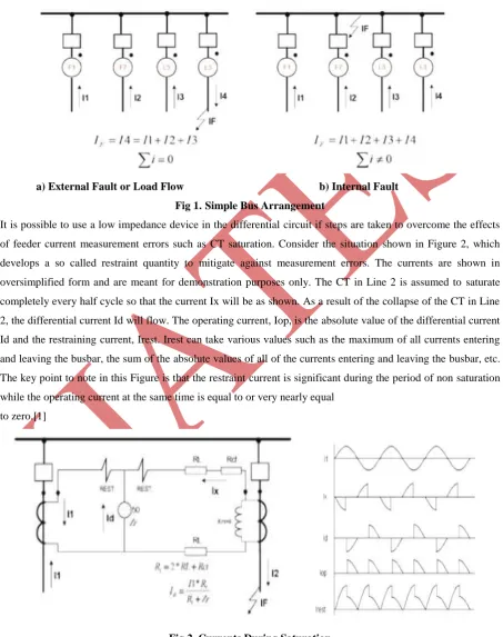
Consider the two situations demonstrated for the simple bus shown in Figure 1.
In case of an external fault, the current leaving the bus is equal to the sum of all of the currents entering the bus,
and the total summation is zero. The same would be true when considering load flow. On the other hand, in case
of feeder currents is not zero). An ideal differential relaying system takes advantage of the fact that the sum of
the feeder currents will be zero for external faults or load flow, whereas the sum will be equal to the total fault
current for internal faults. Unfortunately, there are problems introduced wherein the ideal cannot always be
obtained, and steps must be taken to insure that the differential relaying system works properly, even under
non-ideal conditions.[1]
a) External Fault or Load Flow b) Internal Fault
Fig 1. Simple Bus Arrangement
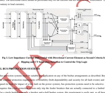
It is possible to use a low impedance device in the differential circuit if steps are taken to overcome the effects
of feeder current measurement errors such as CT saturation. Consider the situation shown in Figure 2, which
develops a so called restraint quantity to mitigate against measurement errors. The currents are shown in
oversimplified form and are meant for demonstration purposes only. The CT in Line 2 is assumed to saturate
completely every half cycle so that the current Ix will be as shown. As a result of the collapse of the CT in Line
2, the differential current Id will flow. The operating current, Iop, is the absolute value of the differential current
Id and the restraining current, Irest. Irest can take various values such as the maximum of all currents entering
and leaving the busbar, the sum of the absolute values of all of the currents entering and leaving the busbar, etc.
The key point to note in this Figure is that the restraint current is significant during the period of non saturation
while the operating current at the same time is equal to or very nearly equal
to zero.[1]
Fig 2. Currents During Saturation
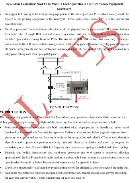
The relay shown in Figure 3 takes advantage of this condition to prevent operation during external faults with
operation, in less than one cycle, can be obtained for heavy faults. The current differential element shown in
Figure 3 is in effect a percentage restrained over current relay; i.e., the differential element (4) produces an
output when the operating current (Iop) exceeds Kr percent of the restraining current (5). This relay also
requires that all of the CT leads be brought into the relay house for connection to the relay. Additionally there is
a directional element (10) that is used to supervise the tripping of the differential unit in case of CT saturation .
The directional principle (block 10) checks if the currents of significant magnitudes (as compared with the fault
current):[2],[3]
• flow in one direction (internal fault) or,
• one of them flows in the opposite direction as compared with the sum of the remaining currents (external
fault). The directional check should be performed only for the currents that are fault current “contributors” (in
contrary to load currents).
Fig 3. Low Impedance Current Differential with Directional Current Element as Second Criteria for
Ripping and CT Saturation Detection to Control the Trip Logic
II. BUS PROTECTION SYSTEMS
Bus protection systems must be suitable for application on any of the busbar arrangements as described. Beyond
the standard protection requirements of reliability (both dependability and security for all fault events) and high
speed (to limit the impact of a bus fault on the power system), bus protection systems need to be selective. This
requires that a bus protection system only trip the feeder breakers that are actually connected to a faulted bus.
For a single busbar system or a breaker and-a-half busbar system, this requirement is easily met, as all breakers
can only connect to one bus. However, for more complex arrangements, such as the double busbar system, this
requirement for selectivity is more difficult to meet. This sets the following requirements for bus protection
systems:[3],[4]
Providing independent protection zones with independent protection settings for each bus segment.
Monitoring which bus segment each feeder or source to the bus is connected to.
Tripping only the breakers connected to a faulted bus segment.
2.1. Centralized Busbar Protection
In a centralized busbar protection system, all field wiring is brought directly to the bus protection relay. This
requires massive amounts of field wiring connected to a single relay panel. The relay panel wiring, and field
wiring, is complicated and time-consuming to design and install.
2.2. Distributed Busbar Protection
In a distributed system, field wiring for each feeder or bay is connected to a bay unit. Each bay unit is then tied
to a central processing unit by digital communications. In most existing designs, the bay units are actually relays
that send current measurements to, send equipment status to, and accept trip commands from the central unit via
a proprietary communications method. Ideally, all field wiring ends in the feeder bay by connecting to the bay
unit, but in many applications, the bay units are actually installed in the control house in panels adjacent to the
central unit. Busbar protection systems using both methods meet the protection requirements for complex bus
arrangements. The challenge for traditional solutions is that field wiring is complex and time consuming, and
that the bus protection system and field wiring is completely dedicated to bus protection.[3],[4],[5]
III. BUS PROTECTION USING PROCESS BUS
A typical process bus architecture involves process interface units (PIUs) distributed throughout the substation
switchyard to acquire signals at primary equipment. To implement bus protection, a bus protection system
simply needs to connect to, and acquire data from, PIUs located at the appropriate current transformers, circuit
breakers, and isolators. It is intuitive, then, that bus protection using process bus uses a distributed architecture,
using PIUs as opposed to bay units. All protection and control functions will be implemented in a central
relaying unit that connects to the appropriate PIUs.
In fact, bus protection is a good first use for process bus. The concept of a station-wide distributed architecture,
with remote acquisition of data, is a well-established architecture for bus protection. Process bus simply changes
the nature of the bay units by using PIUs, and uses an industry standard communications method, IEC 61850, as
opposed to proprietary methods. The capital cost of a bus protection system using process bus and PIUs should
compare to a traditional distributed bus protection architecture using bay units. The advantage to the process bus
system is twofold: wiring costs should be reduced over traditional bus protection using process bus, and the
PIUs installed for bus protection can also supply the same data to other relays for other zones of protection via
process bus communications. Therefore, bus protection provides a built-in expansion and upgrade path for
protection and control systems in the substation.[4],[5]
IV.
NEW DISTRIBUTED BUS PROTECTION SYSTEM USING PROCESS BUS
This paper describes a new Distributed Bus Protection System using process bus. The goal of this new system is
to start to meet the needs of the Smart Substation. The new system uses a central relaying unit for all protection
and control functions, uses PIUs to acquire all signals from and provide control of primary equipment, and uses
IEC 61850 communications between the central relaying unit and the PIU. The central relaying unit, in addition,
collects all related and necessary data in one device. So this new Distributed Bus Protection System addresses
the Smart Substation goals of reducing field wiring, implementing one communications protocol for all access
levels, and starts on facilitating easy data access. In addition, this system can be a future platform for further
Fig 4. Overall Scheme of the Process Bus Based Bus Protection System
V.
SOLVING THE COST OF FIELD WIRING
As previously described, bus protection for large bus architectures is costly due to the time to design, install and
commission all of the associated field wiring. Every source in a bus protection zone requires extensive field
wiring for the relay to acquire the current measurements and equipment status, and to issue control commands.
Every signal used by bus protection requires a pair of copper wires. Every one of these wires between the
primary equipment and the relay, and the terminations of these wires, must be designed, installed and
commissioned for the specific project. Every one of these wires will be wired in series or parallel to protective
relays associated with the zones of protection for the source, so this effort will be duplicated. This process is
exceedingly labor-intensive, with most of the labor requirements being on-site manual labor. The end result is a
very intensive and error-prone process that adds significant time and cost to every project and makes long term
maintenance costly, and changes difficult to implement. This effort is very much the same if the project is
installing a new bus protection system, or simply adding an additional source to an existing system.[9]
The new Distributed Bus Protection System changes the focus of bus protection to that of application by
replacing most of the field wiring with distributed I/O and fiber optic cables. The protection system consists of a
distributed process interface (data acquisition and tripping) architecture using PIUs as bay units, with centralized
processing performed by a single IED.
Fig 5. Extensive Amounts Of Copper Cables Need To Be Distributed From Each Switchyard Apparatus
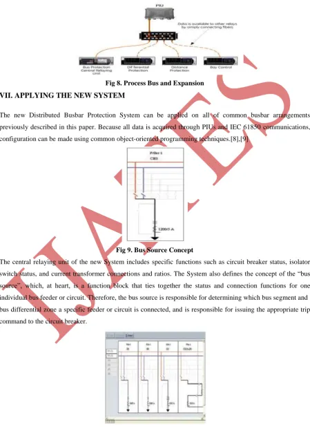
Fig 6. Many Connections Need To Be Made In Each Apparatus In The High Voltage Equipment
Switchyard
All copper field wiring is between primary equipment in the switchyard and PIUs, which ideally should be
located at the primary equipment in the switchyard. Fiber optic cables connect PIUs to the central bus
protection unit.
For all applications, the installation is then identical: the physical interface consists of PIUs connected to a
fiber optic cable. A single IED is mounted in a relay cabinet, with the process cards in the unit patched to
the fiber optic cables coming from the PIUs. The size of the IED, and the fact that there only fiber optic
connections to the IED (with no field wiring) simplifies the relay panel, Therefore the relay panel design for
all busbar arrangements and bus protection schemes is identical: one central relaying unit mounted in a
relay panel, along with fiber optic patch panels.
Fig 7. PIU Field Wiring
VI. PROTECTION
The central relaying unit of new Distributed Bus Protection system provides robust and reliable protection for
all bus protection applications. Highlights of the protection functions related to bus protection include:
Multi-zone differential protection with both restrained (dual slope percent or biased) and unrestrained
(unbiased or instantaneous) functions incorporated. Differential protection is fast (typical response time: 1
power system cycle) and secure. Security is achieved by using a fast and reliable CT saturation detection
algorithm and a phase comparison operating principle. Security is further enhanced by support for
redundant process interface units (Bricks). Supports both three-phase tripping and individual phase tripping.
Dynamic bus replica functionality and multi-zone protection (up to 6 zones) is supported allowing
application of the Bus Protection to multi-section reconfigurable buses. A zone expansion/contraction to an
open breaker feature is included. Isolator position monitoring for up to 96 isolators.
Check-zone functionality configured by programming one of the differential zones to enclose the entire bus.
Additional bus protection functions including end fault protection, breaker fail and over current protection
All protection and control functions are implemented in the central relaying unit, including breaker failure. The
PIU is intended to be a device located at primary equipment in the switchyard, and as such, is only a simple I/O
device, and has no sophisticated processing. Sophisticated processing and application functions are best utilized
in the central relaying unit.
Fig 8. Process Bus and Expansion
VII. APPLYING THE NEW SYSTEM
The new Distributed Busbar Protection System can be applied on all of common busbar arrangements
previously described in this paper. Because all data is acquired through PIUs and IEC 61850 communications,
configuration can be made using common object-oriented programming techniques.[8],[9]
Fig 9. Bus Source Concept
The central relaying unit of the new System includes specific functions such as circuit breaker status, isolator
switch status, and current transformer connections and ratios. The System also defines the concept of the “bus
source”, which, at heart, is a function block that ties together the status and connection functions for one
individual bus feeder or circuit. Therefore, the bus source is responsible for determining which bus segment and
bus differential zone a specific feeder or circuit is connected, and is responsible for issuing the appropriate trip
command to the circuit breaker.
The bus protection carries the object-oriented modeling even farther. The dynamic bus replica, to ensure
protection zones match the actual power system conditions, is another function block. The dynamic bus replica
is simply multiple bus sources connected together through configuration.
VIII.
QUICKLY EXPAND THE PROTECTION SYSTEM THROUGH PROCESS BUS
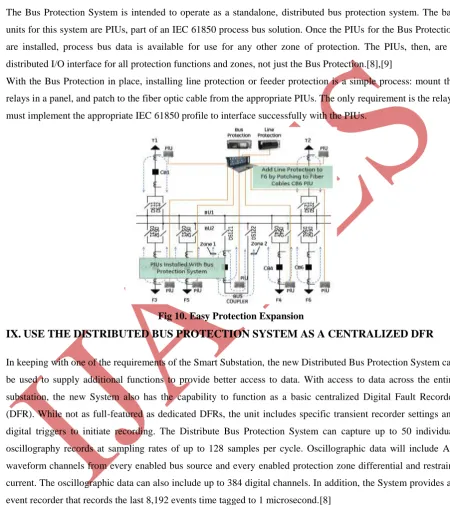
The Bus Protection System is intended to operate as a standalone, distributed bus protection system. The bay
units for this system are PIUs, part of an IEC 61850 process bus solution. Once the PIUs for the Bus Protection
are installed, process bus data is available for use for any other zone of protection. The PIUs, then, are a
distributed I/O interface for all protection functions and zones, not just the Bus Protection.[8],[9]
With the Bus Protection in place, installing line protection or feeder protection is a simple process: mount the
relays in a panel, and patch to the fiber optic cable from the appropriate PIUs. The only requirement is the relays
must implement the appropriate IEC 61850 profile to interface successfully with the PIUs.
Fig 10. Easy Protection Expansion
IX.
USE THE DISTRIBUTED BUS PROTECTION SYSTEM AS A CENTRALIZED DFR
In keeping with one of the requirements of the Smart Substation, the new Distributed Bus Protection System can
be used to supply additional functions to provide better access to data. With access to data across the entire
substation, the new System also has the capability to function as a basic centralized Digital Fault Recorder
(DFR). While not as full-featured as dedicated DFRs, the unit includes specific transient recorder settings and
digital triggers to initiate recording. The Distribute Bus Protection System can capture up to 50 individual
oscillography records at sampling rates of up to 128 samples per cycle. Oscillographic data will include AC
waveform channels from every enabled bus source and every enabled protection zone differential and restraint
current. The oscillographic data can also include up to 384 digital channels. In addition, the System provides an
event recorder that records the last 8,192 events time tagged to 1 microsecond.[8]
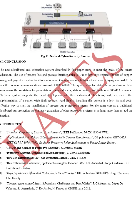
X. CYBER SECURITY AND PROCESS BUS
This new Distributed Bus Protection System is designed specifically to address the cyber security problem. The
Communications architecture is a point-to-point architecture, with no remote access to the communications
between the Protection central unit and the PIUs. The messaging between the relay and the PIUs is completely,
Fig 11. Natural Cyber-Security Barrier
XI. CONCLUSION
The new Distributed Bus Protection System described in this paper starts to meet the goals of the Smart
Substation. The use of process bus and process interface units (PIUs) as bay units reduces the use of copper
wiring and project execution time to a minimum. Communications between the central relaying unit and PIUs
uses the common communications protocol of IEC 61850. The system also facilitates the acquisition of data
from across the substation for presentation to other devices, station control, and traditional SCADA services.
The new system supports the rapid development of other station-wide functions, and has started the
implementation of a station-wide fault recorder. And finally, installing this system is a low-risk and
cost-effective way to start the installation of process bus protection systems. For the same cost as a traditional
distributed bus protection system, easy expansion of other protection systems is nothing more than an add-on
function.
REFERENCES
[1] “Transient Response of Current Transformers”, IEEE Publication 76 CH 1130-4 PWR.
[2] “Application of PVD Relays Using Different Ratio Current Transformers”, GE publication GET-6455.
[3] “IEEE C37.97-1979 (1990) Guide for Protective Relay Applications to Power System Buses”.
[4] “The Art and Science of Protective Relaying”, C. Russell Mason
[5] “Protective Relaying, Principles and Applications”, J. Lewis Blackburn
[6] “B90 Bus Differential relay”: UR Instruction Manual. GEK-113200
[7] “Bus Differential Protection”, Spokane Washington, October 1995. J.G. Andrichak, Jorge Cardenas. GE
Protection & Control
[8] “High Impedance Differential Protection in the MIB relay”. GE Publication GET- 8495. Jorge Cardenas,
John Garrity
[9] “The next generation of Smart Substations. Challenges and Possibilities”, J. Cárdenas, A. López De