EXPERIMENTAL STUDY OF EFFECT
OF END SILL ON STILLING BASIN
PERFORMANCE
H.L.Tiwari
Department of Civil Engineering, Maulana Azad National Institute of Technology, Bhopal, Madhya Pradesh INDIA
Arun Goel
Department of Civil Engineering, National Institute of Technology, Kurukshetra, Haryana, INDIA.
V. K. Gahlot
Department of Civil Engineering, Maulana Azad National Institute of Technology, Bhopal, Madhya Pradesh INDIA
Abstract
This research paper presents an experimental study of end sill for new stilling basin models in dissipation of energy for a rectangular shaped pipe outlet of size 10.8cm x 6.3 cm. The models were tested for three Froude numbers namely 1.85, 2.85 and 3.85 in the laboratory. The new models are developed by changing the shape of end sill. The scour (magnitude and location) after the end sill were measured for each model. The results have indicated that for all flow conditions, the sloping end sill is more effective in lowering the downstream kinetic energy than other end sills tested,
Keywords: Scour, Stilling basin, Froude number, End sill.
Introduction
End sill plays an important role in the design of stilling basin for reducing the length of it and also helps to improve the flow pattern downstream of the channel . End sill my be defined as a vertical ,stepped, sloped or dentated / solid wall at the downstream end of the stilling basin, Edward, A(1959). Stilling basins are employed for the purpose of dissipating the excessive energy downstream of hydraulic structures like overflow spillways, sluices, pipe outlets etc. Various types of recommended stilling basin designs for pipe outlets recommended are by Bradely and Peterka (1957), Fiala and Albertson (1961), Keim (1962), Flammer et al. (1970), Vollmer and Khader (1971) Garde and Saraf (1986), Smith (1988), Goel and Verma (1999, 2001) and Goel (2008) etc. In all above mentioned studies, end sills used are either sloping Peterka (1957), or semicircular, Goel and Verma (2000). The previous models developed by past investigators are either too long or not working efficiently except the models developed by Goel (1999, 2001, 2008) which are applicable to circular shaped outlets only. The present research paper concentrates to study the effect of the shape &size of the end sill to develop new models for rectangular pipe outlet stilling basin.
Experimental arrangement
testing. A manual tail gate was used at the end of the flume to control the tail water depth in the flume for experimentation. The time for each test run was kept as one hour. The one hour duration was found to be sufficient as 90% of the scour occurred in 45 min for range of Froude numbers used as observed by experimental run, conducted as a trial at the beginning of the testing. The maximum depth of scour (dm) and its distance from end sill (ds) was measured for each test run after one hour run time. The depth of flow over the erodible bed was maintained equal to the normal depth of flow, which was computed by Manning’s formula corresponding to the inflow Froude number Fr=V/(gd) 0.5,where V is the average velocity in the pipe , g is the acceleration due to gravity and d is the equivalent diameter of the pipe. The erodible sand bed was leveled up to the top of the end sill for observation of the scour pattern. First of all bed material was filled up to the height of end sill and get leveled then normal depth was maintained over the sand bed by allowing the water from the overhead tank inside the flume by operating the tail gate. After that centrifugal pump of capacity 20 HP was switched on, keeping the control valve closed, fitted into the feeding pipe. The flow into the flume was increased gradually so as to achieve required Froude number with a minimum possible disturbance to the erodible sand bed. The discharge was measured by a calibrated venturimeter installed in the delivery pipe. With the operation of tail gate, the desired steady flow condition with normal depth was maintained. After one hour test run, the motor was switched off. The value of maximum depth of scour (dm) and its location from the end sill (ds) were noted. All the models were tested for constant run time of one hour and with the same erodible material for three Froude numbers namely 1.85, 2.85 and 3.85. Different stilling basin models were tested by changing shape of end sills.
Scheme of experimentation
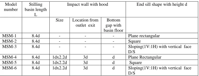
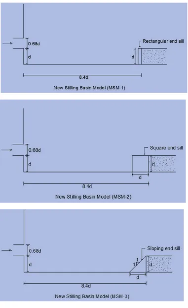
First of all basin floor was designed for the inflow Froude number (Fr = 3.85 ) and was fabricated in the flume as per USBR impact type model ,which consists of an impact wall of size 1d x 2.2d with a bottom gap 1d, located at 3d from exit of pipe outlet and followed by sloping end sill of height 1d positioned at 8.4 d where d is the equivalent diameter of the pipe outlet. Later on, in order to study the effect of end sill shape, new stilling basin models were fabricated by changing shapes of end sills (06 Models) fig. no. 1-2. During the test runs for all the stilling basin models, the grain size of the material forming the erodible bed and test run time were kept the same. The details of new models have been mentioned in Table No 1.
Table No. 1
Model number
Stilling basin length
L
Impact wall with hood End sill shape with height d
Size Location from
outlet exit
Bottom gap with basin floor
MSM-1 8.4d - - - Plane rectangular
MSM-2 8.4d - - - Square
MSM-3 8.4d - - - Sloping(1V:1H) with vertical face
D/S
MSM-4 8.4d 1dx2.2d 3d d Plane Rectangular
MSM-5 8.4d 1dx2.2d 3d d Square
MSM- 4
MSM- 5
MSM- 6
Performance evaluation
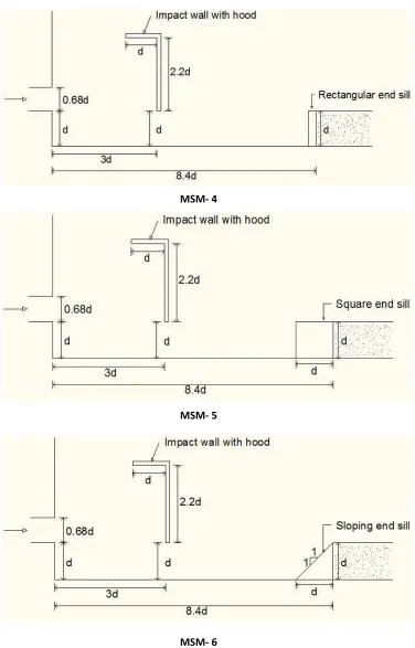
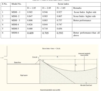
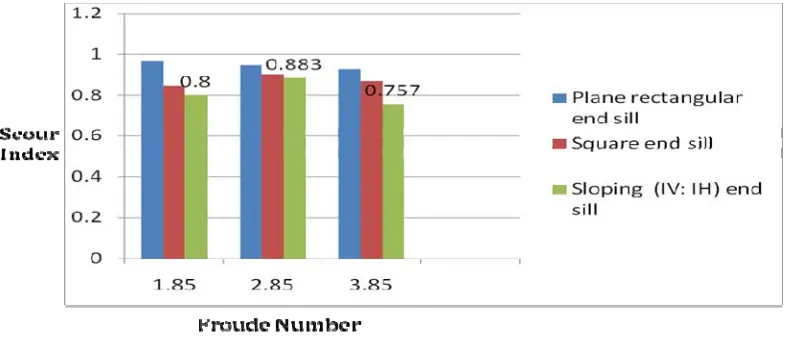
The performance of stilling basin tested for different Froude number (Fr) is a function of channel velocity (v), the maximum depth of scour (dm) and its location from end sill (ds). A stilling basin model that produces smaller depth of scour at a longer distance is consider to have a better performance as compared to another stilling basin which results in a larger depth of scour at a shorter distance when tested under similar condition. Verma & Goel (2003). A non dimensional scour index (2dm/ds), Goel & Verma (2001), has been considered for comparison of performance of stilling basin models. A smaller value of scour index shows better performance of stilling basin models. The value of scour indices for various runs on each model for different Froude numbers are given in Table No. 2.
Table no. 2 Values of Scour Index (tan α = 2dm/ds)
S No. Model No. Scour index
Fr = 1.85 Fr = 2.85 Fr = 3.85 Remarks
1 MSM – 1 0.965 0.946 0.927 Scour Index higher side
2 MSM -2 0.847 0.903 0.867 Scour Index higher side
3 MSM - 3 0.800 0.883 0.757 Better performance
4 MSM-4 0.826 0.844 0.747 5 MSM-5 0.680 0.710 0.656
6 MSM-6
0.609 0.705 0.593
Better performance than allabove
Figure No.3 Scour Profile
Result and discussion
MSM-4 to MSM-6 shows that sloping end sill performs better as shown in figure no.4. The model MSM-4 having rectangular end sill further goes down as compared to model MSM-5 with square end sill and far inferior as compared to model MSM-6 as shown below.
Figure No. 4
Figure No. 5
Conclusions
energy for all flow conditions as compared to other end sills tested for rectangular pipe outlet basin . There is a scope to reduce the length of pipe outlet stilling basin by way of experimentations.
References
[1] Bradley, J.N. and Peterka, A. J. (1957) Hydraulic Design of Stilling Basins, (1-6 Papers). Journal of A.S.C.E., Hydraulic Engg, October, pp.1401-1406.
[2] Elevatorski, Edward, A. Hydraulic Energy Dissipators. McGraw Hill Book Company, Inc., New York. 1959.
[3] Fiala, J. R. and Maurice, L. Albertson ( 1961) Manifold Stilling Basins. Journal of A.S.C.E., Hydraulic Div. No 4, Vol. 87, Paper no 2863, pp.55-81.
[4] Flammer, G.H, G.V.Skogerboe, C.Y. Wei and H. Rasheed (1970) Closed Conduit to Open Channel Stilling Basins. Journal of A.S.C.E., Irrigation and Drainage Div, Vol.96, paper 7124, pp.1-1.,
[5] Garde, R .J. and Saraf, P.D. (1986) Evolution of Design of Energy Dissipator for Pipe Outlets. J. of Irrigation & Power, July, pp.145-154.
[6] Goel, A. and Verma, D.V.S (2000) Stilling Basins for Outlets Using Wedge Shaped Splitter Blocks Journal of Irrigation and Drainage Engineering, American Society of Civil Engineering (ASCE), May/June, pp.179-184.
[7] Goel, A. and Verma D.V.S. (2001) Model Studies on Stilling Basins for Pipe Outlets. J. of Irrigation and Drainage Systems, Kluwer Academic Publisher, The Netherlands, Vol.15, No.1. 81-91.
[8] Goel A. (2008) Design of Stilling Basin for Circular Pipe Outlet. Canadian Journal of Civil Engineering, Vol. 35, No. 12, pp. 1365-1374.
[9] Goel, A. and Verma, D.V.S (2003) Development of Efficient Stilling Basins for Pipe Outlets Journal of Irrigation and Drainage Engineering, American Society of Civil Engineering. May/June, pp.194-200.
[10] Keim, S.R. (1962) Contra Costa Energy Dissipator. Journal of A.S.C.E., Hydraulic Division, Paper 3077, March, pp. 109-122. [11] Vollmer, E. and Khader M.H.A.( 1971) Counter Current Energy Dissipator for Conduit Outlets. International J. of Water Power, July,