© 2017 IJSRSET | Volume 3 | Issue 2 | Print ISSN: 2395-1990 | Online ISSN : 2394-4099 Themed Section: Engineering and Technology
Parametric Study of R C Frames with Raft Foundation
Considering Soil Structure Interaction
Dr. S. S. Patil.
1, Dyawarkonda S. S.
21 Professor and Head, Civil Engineering Department, Walchand Institute of Technology, Solapur, India 2 P.G. Student, Department of Civil Engineering Department, Walchand Institute of Technology, Solapur, India
ABSTRACT
In conventional method of design of raft foundation, base flexibility due to soil mass is ignored. The purpose of this study is, to understand the effect of soil flexibility on the performance of the building frames resting on raft foundation. The Soil Structure Interaction (SSI) study is carried out on symmetrical building space frame of 4bay in both x and y direction, for 10 storey(Model 1),15 storey (Model 2), 20 storey (Model 3) and 25 storey(Model 4) building frame with raft foundation under fixed base and flexible base condition. In this analysis three types of soil i.e. Hard soil, Medium hard soil and Soft Soil are used for soil structure interaction (SSI) study. The analysis carried out using Equivalent Static Method (ESM) in accordance with IS1893-2002. The soil flexibility is incorporated in the analysis by using Winkler approach ( Spring Model). SAP-2000 software. is used to model building frame for fixed base and flexible base. The effect of SSI on various structural parameters like beam moment, column moment and roof displacement are discussed. The comparison is made between fixed base and flexible base conditions.
Keywords:Raft foundation, Soil Structure Interaction, Building Response, Equivalent Static Method, , Winkler Method.
I.
INTRODUCTION
Most of the civil engineering structures involve some type of structural element with direct contact with ground. When the external forces, such as earthquakes, act on these systems, neither the structural displacements nor the ground displacements, are independent of each other. The process in which the response of the soil influences the motion of the structure and the motion of the structure influences the response of the soil is termed as soil-structure interaction (SSI).
Most of the design codes use oversimplified design spectrums, which attain constants acceleration up to a certain period, and thereafter decreases monotonically with period. Considering soil structure interaction makes a structure more flexible and thus, increasing the natural time period of the structure compared to the corresponding rigidly supported structure. Interaction effect is ignored to simplify the mathematical model but neglecting the interaction between soils and structures
may result in a design that is either unnecessarily costly or unsafe.
II.
RELATED WORK
The SSI analysis is done by the Raft foundation and providing spring of equivalent stiffness (Discrete Support) to the raft foundation. A more rational solution of soil-structure interaction problem can be achieved with computational validity and accuracy by appropriate analysis. Winkler’s idealization (1867)[1]
limitation, yields reasonable performance and it is very easy to exercise. B.R. Jayalaxmi et al (2009)[5] studied earthquake response of
multi-storeyed RC frame with soil structure interaction effects by modelling structure–foundation-soil system by Finite Element Method. Seismic response buildings considering SSI exhibit variation based on frequency content of motion and stiffness of soil.
III.
METHODOLOGY
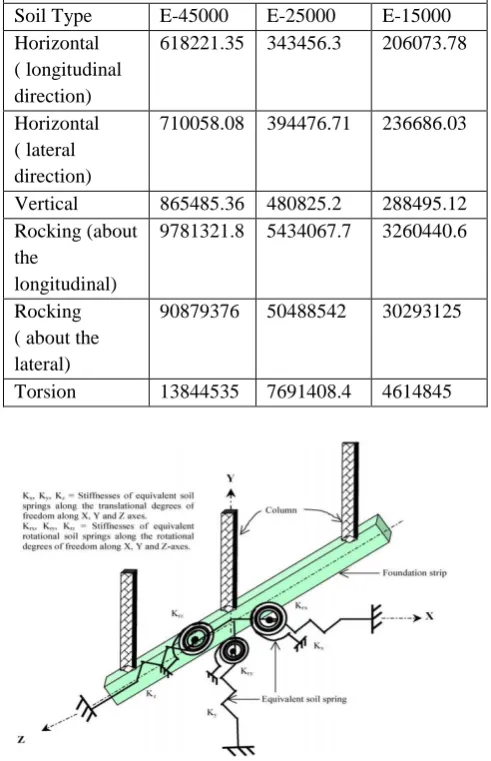
Hard Soil, Medium Hard Soil and Soft Soil are the three types of soil over which the building frames are considered to be resting. The properties of soil with the elastic constant of these three soils are considered as per Bowel’s (The soils are designated as per the modulus of Elasticity as shown in the Table. No.1).[6]
Table I Soil Elastic Constants
The values of stiffness for various types of soils considered for study are calculated as per Table II and are shown in Table III.
Table II Spring Stiffness (George Gazeta)
where, Ab= Area of the foundation considered; B and L=
Half-width and half-length of a rectangular foundation, respectively; Ibx, Iby, and Ibz = Moment of inertia of the
foundation area with respect to longitudinal, lateral and vertical axes, respectively.
Table III Spring Stiffness Values
Figure 1. Equivalent Spring Stiffness
Symmetric frames of 4 bays 10 storey, 15 storey, 20 storey and 25 storey resting on raft foundation are considered. The details of the building frames are given in Table IV.
Soil Type
Designati-on
Modulus of Elasticity (kN/m2)
Poisson’ s Ratio (µ)
Unit Weight (γ) (kN/m3 )
Hard
soil E-45000 45000 0.4 16
Mediu m hard soil
E-25000 25000 0.4 16
Soft
soil E-15000 15000 0.4 16
Degrees of
freedom Stiffness of equivalent soil spring
Vertical [2GL/(1-ν)](0.73+1.54χ0.75) with χ = Ab/4L2 Horizontal (lateral
direction) [2GL/(2-ν)](2+2.50χ
0.85) with χ = A b/4L2 Horizontal
(longitudinal direction)
[2GL/(2-ν)](2+2.50χ0.85 )-[0.2/(0.75-ν)]GL[1-(B/L)] with χ = Ab/4L2
Rocking (about
longitudinal) [G/(1-ν)]Ibx 0.75
(L/B)0.25[2.4+0.5(B/L)]
Rocking (about
lateral) [G/(1-ν)]Iby 0.75
(L/B)0.15
Torsion 3.5G Ibz0.75(B/L)0.4(Ibz/B4)0.2
Stiffness of Equivalent Soil Spring (kN/m)
Soil Type E-45000 E-25000 E-15000
Horizontal ( longitudinal direction)
618221.35 343456.3 206073.78
Horizontal ( lateral direction)
710058.08 394476.71 236686.03
Vertical 865485.36 480825.2 288495.12 Rocking (about
the
longitudinal)
9781321.8 5434067.7 3260440.6
Rocking ( about the lateral)
90879376 50488542 30293125
Table IV Geometric and Material Properties of Frame, Footing and Type of Soil
Component Description Data Frame
Details
Number of
storey’s 10,15,20,25 Number of bays in
X direction 4 Number of bays in Y direction 4 Storey Height in
(M) 3.2 Bay width in X
direction inM 6 Bay width in Y
direction inM 6
Size of beam in M 0.23X 0.4 Size of column As per design Thickness of Slab
in M 0.125
Foundation
Raft foundation 26m x 26m, 1.05 m depth
Elastic modulus of
Concrete in kN/m2 2.5 x 10
7
Poisson’s ratio of
Concrete 0.2
Soil Properties
Modulus Elasticity of Soil in kN/m2
45000, 25000,15000 Poissions ratio of
Soil 0.4
IV.
PLACEMENT
OF SPRINGS
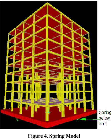
The building is designed as per IS code (IS 456:2000).The dimensions of all element the structure and foundation are considered as per the design. The constant depth is considered for all the frame , to analyse and compare the behaviour of the structure for various base conditions. The details of building frame and placement of the springs are shown in Fig.2 and Fig.3. The springs are kept as per the guidelines of Sekhar Chandra Dutta, Koushik Bhattacharya, Rana Roy (2004) [4] considered low-rise building frames resting on shallow foundations, viz. isolated and grid foundation.
Figure 2. Frame Details
Figure 4. Spring Model
Fig. No 4 shows four storey building frame modeled in SAP 2000 software.
V.
EXPERIMENTAL RESULTS
The present study is carried out to evaluate the effects of SSI for R.C framed structure. Four types of frames (4x4x10), (4x4x15), (4x4x20) and (4x4x25) are considered for the analysis. This analysis is carried over an raft foundation with fixed base and flexible base. Equivalent Static Method is used to Carry out the analysis as per IS 1893:2002. The analysis of fixed base model and flexible base model are performed in SAP2000. From this analysis effects of SSI on various parameters like beam moment, column moment and Roof displacement are presented and discussed accordingly.
5.1 Beam Moment
The variation in Beam moment for the fixed base and flexible base conditions for 10 storey, 15 storey, 20 storey and 25 storey building frames are shown in Fig.6.
Figure 6. Beam Moment for different support condition for all frames
For the given building frames it is observed that beam moment is increases with increase in soil flexibility.
The same tread is observed for the all buildings frames.
With increase in soil flexibility and building height beam moment increases with higher rate
The increment in beam moment for hard soil to medium hard soil is more, where as it is marginal for the medium hard to soft soil.
The variation in beam moment from hard to soft soil is lesser in low rise building as it is higher in high rise building.
It is concluded that, the variation in beam moment is 60 to 98 % from hard to soft soil.
5.2 Column Moment
The variation in Column moment for the fixed base and flexible base conditions for 10 storey, 15 storey, 20 storey and 25 storey building frames are shown in Fig.7.
Figure 7. Column Moment for different support condition for all frames
The increment in column moment for hard soil to medium hard soil is more, where as it is marginal for the medium hard to soft soil.
The variation for column moment for hard to medium hard soil is stiff and is linear for the medium hard to soft soil.
The variation in column moment from hard to soft soil is lesser in low rise building as it is higher in high rise building.
It is concluded that, the variation in column moment is 1-2 times more from hard to soft soil.
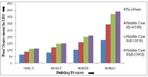
5.3 Roof Displacement
The variation in Roof Displacement for the fixed base and flexible base conditions for 10 storey, 15 storey, 20 storey and 25 storey building frames are shown in Fig.6.
Figure 8. Roof Displacement for different support condition for all frames
For the given building frames it is observed that roof displacement is increases with increase in soil flexibility.
The rate of increase in roof displacement for hard soil to medium hard soil is more, where as it is marginal for medium hard soil to soft soil.
For the given base condition the rate of increment in roof displacement is higher for high rise building.
With increase in soil flexibility and building height roof displacement increases with higher rate
It is concluded that, the variation in roof displacement for in case of high rise building is observed as 2-3 times
VI.
CONCLUSION
The results of Roof Displacements, Beam Moment and Column Moment with fixed base are increasing with soil flexibility.
The maximum increment in Roof Displacements, Beam Moment and Column Moment with respective to fixed base, for each model is observed for flexible case III.
The results of Roof displacement of all models indicate that the major impact of soil flexibility and SSI effect is on Roof displacement which is important response quantity of building. Particularly for cases of building with soft soil the roof displacement magnified by 2.2 times the roof displacement of building with fixed base. Therefore, SSI is to for the design of the structures.
The trend of the result for Roof Displacement, was increasing for flexible case I, case II and case III with respect to increase in height of the structure; however the % increase in Beam Moments and Column Moment due to flexible base case I, case II and case III goes on reducing as height of the structure increases.
VII.
REFERENCES
[1] (Winkler (1867) proposed a foundation model consisting of closely spaced independent linear springs. These models are used to consider the flexibility of soil in the analysis of structures. [2] George Gazetas, Member, ASCE, “Formulas and
charts for impedances of surface and embedded foundations.”
[3] Sekhar Chandra Dutta, Rana Roy, “A critical review on idealization and modeling for interaction among soil-foundation structure system”, Computers and Structures 80 (2002), pp.1579_1594
[4] Sekhar Chandra Duttaa,*Koushik Bhattacharyaa, Rana Royb (2 July 2004) Response of low-rise buildings under seismic ground excitation incorporating soil–structure interaction
[5] B.R. Jayalekshmi, “Earthquake response of multistoried R.C. frames with soil structure interaction effects.”
[6] Bowles, J.E.(1998).”Foundation Analysis and design”, McGraw Hills, New York.
[7] IS 1893 (Part I): 2002 Criteria for Earthquake Resistant Design of Structures-General provisions and Buildings, Bureau of Indian Standards, New Delhi.