© 2017 IJSRSET | Volume 3 | Issue 3 | Print ISSN: 2395-1990 | Online ISSN : 2394-4099 Themed Section: Engineering and Technology
PMSG Based Wind Farm Analysis in ETAP Software
Anupam
*1, Prof. S.U Kulkarni
21Department of Electrical Engineering,Bharati Vidyapeeth Deemed University College of Engineering, Pune, Maharashtra, India [email protected]
2Department Department of Electrical Engineering, Vidyapeeth Deemed University College of Engineering ,Pune, Maharastra, India [email protected] 2
ABSTRACT
This paper present the variable speed wind turbine with direct driven permanent magnet synchronous generator(PMSG) is considered for dynamic behaviour of system. The simulation is performed in ETAP software. The load flow analysis is performed for exhibiting variability in the output power as a result of change in the wind speed and short circuit analysis is done for symmetrical and unsymmetrical faults . Here proposed wind farm model is simulated in the ETAP software and The analysis is carried out to understand the behaviour of system before implementation on the actual wind farm.
Keywords : PMSG - permanent magnet synchronous generator, ETAP-Electrical Transient Analysis Program, symmetrical and unsymmetrical faults, PMSG- permanent magnet synchronous generator, ETAP-Electrical Transient Analysis Program, symmetrical and unsymmetrical faults.
I.
INTRODUCTION
This paper present the variable speed wind turbine with direct driven permanent magnet synchronous generator (PMSG) is considered for dynamic behaviour of system. The simulation is performed in ETAP software. The load flow analysis is performed for exhibiting variability in the output power as a result of change in the wind speed and short circuit analysis is done for symmetrical and unsymmetrical faults. Here proposed wind farm model is simulated in the ETAP software and The analysis is carried out to understand the behaviour of system before implementation on the actual wind farm[1].
The permanent magnet synchronous generator is used very often in variable speed wind energy system[2]. As it results in higher efficiency and no slip ring maintenance, it is used enormously in the system for contributing maximum power output and exerting less mechanical stress in contrast with the constant speed system[2]. In earlier days constant speed wind turbines generators (induction generator) was widely used, but due to its various limitation such as low efficiency and poor power quality slow down its application in wind
farm. Advantage of PMSG is its light weight due to absence of gear box, which reduces the weight of nacelle, further leads to the reduction in the cost of WTG [2]. The designing of PMSG is much more easier as compared to other wind turbine system.
With the variable wind speed system, it is possible to obtain the optimum tip speed ratio and hence suitable for the wide spectrum of wind speeds. In this paper
variable-speed directly-driven permanent magnet
synchronous generator (PMSG) architecture model has been considered. Modelling and analysis has been performed in ETAP software. In this research paper, 21 generator system has been included, each of 2.1MW, for the analysis of load flow and short circuit
II.
MODELLING OF WIND SPEED
(t) = (t) + (t) + (t) + (t) ...(1)
Here is base wind , V_r is the ramp wind, V_g is the gust wind and is the noise wind. In this paper average wind speed is considered as 10 m/s. In figure 1, different types of wind component is shown.
Figure 1: Different types of wind component
The aerodynamic output power is expressed as[4]
= ( ρA ...(2)
Where ρ is the air density ( 1.225 kg/m^3, A is swept area of rotor blades (m^2). Cp is power coefficient , β is blade pitch angle(in degrees), V is the wind speed .The tip speed ratio is given by:
= ...(3)
Where is rotor angular velocity and R is the radius of the rotor. Figure 2, explains the different tip speed ratio for different power coefficient.
Figure 2 : TSR Vs
III. PMSG MODELLING
Permanent magnet synchronous generator is used widely today in wind energy conversion system(WECS) with different operating power range. PMSG machine can be developed by using state space model considering its electrical and mechanical system. Due to large air gap present in the PMSG, it is necessary to develop sinusoidal electromotive force in stator flux. Assumption is made that magnetic circuit is linear and cores of stator and rotor do not saturate.
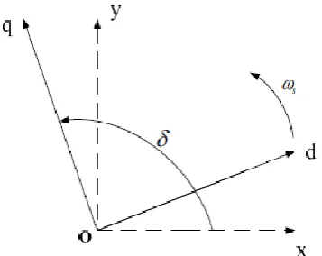
Here in figure 3, d-q frame of reference is considered which is rotating with synchronous speed 𝜔s.The model has been considered in per unit system.
Figure 3 : DQ and XY axis space relationship
Equation of flux and voltage.
=
-
(4)
= -
(5)
=
-𝜔
-
(6)
=
+ 𝜔
-
(7)
Where and is stator flux in dq axis respectively,
where and are d axis and q axis inductance,
are generator side current in d-q axis
respectively. And 𝜔 is angular speed of generator( electrical).
Equation of power:
= + (8)
= + (9)
Where and is generator’s real and reactive power respectively.
= = ( (10)
IV. WIND FARM DESCRIPTION
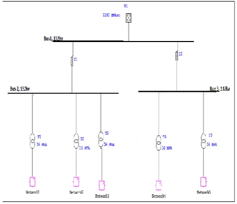
Here 5 network system is designed which consist of total generation of 44.1 MW. First four network consist of 8.4MW and network 5 is of 10.5 MW. The network is connected to 132kv bus via cable to grid [6]. Each network and generator is followed by the transformer unit of 56 MVA and 2MVArespectively. All Wind generators are coupled to a step up transformer of 2MVA, 0.69/33 kV. Here ,Figure 4 demonstrate the single line diagram of the windfarm model.
Figure 4 : Wind farm single line diagram
Wind energy conversion system
In the recent trends there are generally four types of generators in wind power conversion. Type 1 is fixed speed induction generators, type 2 is variable rotor resistance induction generators, type 3 deals with variable speed wind turbine concept with partial-scale power converter and type 4 is variable speed concept with full-scale power converter system. In this paper type 4 generator is used for modelling purpose.[5] This is basically a direct driven permanent magnet synchronous generator (PMSG) gearless wind turbine technology. slip-rings and brushes is not present in the PMSG so less maintenance is needed[5].In figure 5, explains how PMSG based wind turbine is connected in wind farm with converter mechanism. PMSG is more stable than DFIG and SCIG ones resulting higher efficiency. PMSG can also control the real and reactive power as its construction is simple and easy to implement.
Figure 5 : Block diagram of type 4 consist of grid side and stator side convertors.
V.
RESULTS AND DISCUSSION
Load flow Analysis
In this simulation load flow analysis module is used for the finding the active and reactive power at different buses of the wind farm. The method used here is Adaptive Newton Raphson and wind speed is taken as nominal for the analysis. The active power near to grid is 41780 KW. Table 1, represents the simulated power output for different networks.
Table 1 : Active Power at Networks
NETWORKS ACTUAL(
MW)
SIMULATIO N(MW)
Network 1 8.4MW 8.2MW
Network 2 8.4MW 7.9MW
Network 3 10.5MW 9.9MW
Network 4 8.4MW 7.9MW
Network 5 8.4MW 7.9MW
Total power
to grid
42MW 41.1MW
Active and reactive power for wind speeds(10m/s)
Table 2 : Power at Different Wind Speed
Wind speeds(m/s) Power (MW)
4 0.3
5 1.2
6 2.4
7 4.2
8 6.6
9 9.7
10 13.9
11 18.6
12 24.1
13 32.8
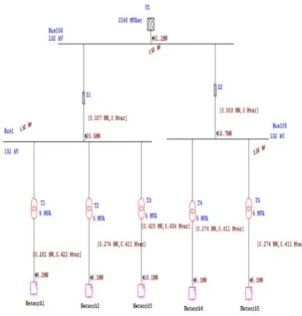
Figure 6, gives the load flow results for different network. The method adopted for load flow analysis was Adaptive Newton Raphson . The total power delivered to the grid was 44.1 MW.
Figure 6: Load flow (simulated results)
VI. SHORT CIRCUIT ANALYSIS
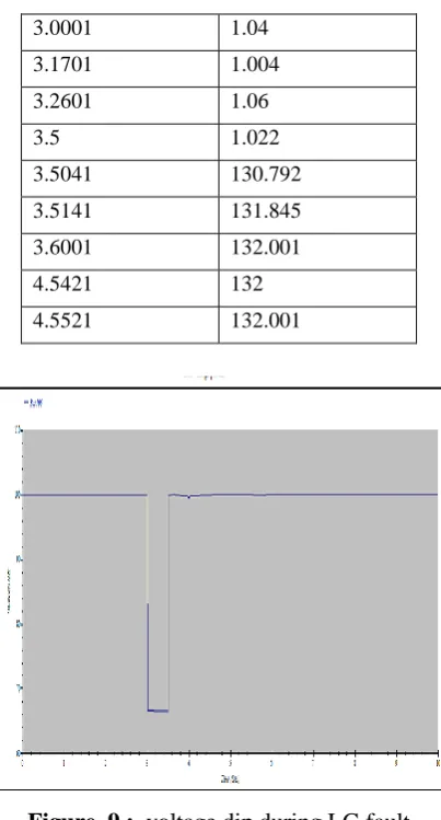
The short circuit analysis is done to obtain the magnitude of short circuit current. It deals with symmetrical and unsymmetrical faults. The fault current for the different types of fault is simulated in this software [5].
Here rated wind speed is taken 10m/s, and generator attains the steady state after the LG fault is recovered by
the system. Fault was made at 3 sec and bus voltage drops and at 3.5 sec again bus voltage regain back system voltage after clearance of the fault. Hence the variable speed wind turbine(VSWT) are able to recover the voltage profile. Here in the given figure three phase and LG fault is introduced at bus 106 and the fault current generated was 9.8 kA and 9.81 respectively. Figure 7 and 8, explains recovery of the voltage profile after the fault has been cleared.
Figure 7 : Simulation results of 3ph fault at bus 1
Impact and clearing of both the faults is studied by simulation results. The total simulation time is considered as 10 seconds. And fault is created at 3 seconds and cleared at 3.5 sec. In 3 phase fault voltage got dipped to almost zero and it get cleared in 1.27 seconds. Table 3 and 4 shows the different time taken for the recovery of voltage.
Figure 8 : Simulation results of LG fault at bus 1
Table 3 : Voltage recovery for 3 ph fault at bus 106
Time(sec Voltage (KV
3.0001 1.04
3.1701 1.004
3.2601 1.06
3.5 1.022
3.5041 130.792
3.5141 131.845
3.6001 132.001
4.5421 132
4.5521 132.001
Figure 9 : voltage dip during LG fault
In case of LG fault, PMSG was able to recover the voltage by following some oscillation
.
Time(sec) Voltage(KV)
2.998 132
3.0001 87.96
3.1701 87.8989
3.2601 87.7
3.5 87.73
3.5041 131.838
3.5141 131.845
3.6001 132.001
4.5421 132
4.5521 132.001
VII.
CONCLUSION
The research work was done in the ETAP software. Analysis explains the capabilities of PMSG based wind farm foe different condition. In the load flow analysis , the optimal power flowing to the grid is simulated here
which was carried out at rated speed of 10 m/s. Furthermore the PMSG driven wind farm is analysed to short circuit faults where 3 ph and LG fault was created at bus 106 and recovery of the system voltage is maintained after 1.27 seconds. This shows that 3ph faults are more severe and corrective action can be applied for wind farm protection.
VIII.
REFERENCES
[1]. Marwan Rosyadi, Atsushi Umemura, Shin'ichi Kondo "Development of Phasor Type Model of PMSG based wind farm for dynamic simulation Analysis. Dept. of Electrical and Electronic Engineering,Kitami-Hokkaido, Japan
[2]. K.Bunjongjit,Y.Kumsuwan"MATLAB/Simulink
Modeling of Stator Current Control of PMSG for Grid-Connected Systems, IEEE 2014.
[3]. Ackermann, T, "Wind Power in Power System", Chichester, UK, John Wiley & Sons, 2012.
[4]. KANG Li1, SHI LiBao1, NI YiXin1, YAO
LiangZhong2. " Small signal stability analysis with penetration of grid-connected windfarm of PMSG type". The International Conference on Advanced Power System Automation and Protection.IEEE2011.
[5]. M.Q. Duong, K.H. Le, F.Grimaccia, S. Leva, M. Mussetta, and R.E. Zich"Comparison of Power
Qualityin DifferentGrid-Integrated Wind
Turbines"IEEE 2014.
[6]. Sripad ganpati desai, "Analysis of a Conventional Fixed Speed Induction Generator based Wind Farm"IEEE , 978-1-5090-0849-0/16/$31.00,2016 [7]. K .Bungjogit, "MATLAB/Simulink Modeling of
Stator Current Control ofPMSG for
Grid-Connected Systems,