PARAMETER ESTIMATION OF VSI
FED PERMANENT MAGNET
SYNCHRONOUS MOTOR BY USING
HARTLEY MODULATING FUNCTION
P. Ramana CH. SURESH KUMAR
Associate Professor, EEE department, GMRIT, M.Tech Student, EEE department, GMRIT, Rajam, Srikakulam, Andhra Pradesh, 532127, India. Rajam, Srikakulam, Andhra Pradesh, 532127, India.
[email protected], [email protected] [email protected]
Dr. K. ALICE MARY Dr. M.SURYAKALAVATHI
Professor & Head, EEE department, VIIT, Professor, EEE department, JNTU, Vishakapatnam, Andhra Pradesh, 533045, India. Hyderabad, Andhra Pradesh, 533045, India
[email protected] [email protected]
ABSTRACT:
This paper discusses modeling and parameter estimation of PMSM. The design of a control system for a high performance drive requires a mathematical model of the motor. This is usually derived from physical principles, then the parameters of the motor are determined through off-line testing or estimated on-line from input/output operating records data. The dynamics of synchronous motor can be described by a set of differential equations relating voltages, currents, speed and torque. The equations represented in d-q axes variables in the rotor reference frame using park’s transformation are presented.
A parameter estimation technique employing the Hartley modulating function (HMF) is detailed. Using the data obtained from open loop simulation physical parameters such as stator resistance and inductances as well as mechanical parameters such as moment of inertia and viscous friction coefficient have been estimated with a fair amount of accuracy. This estimate has been found to be quite sensitive to the choice of sampling period.
Keywords: Permanent magnet synchronous motor, Mathematical modeling, Rotor reference frame, parameter estimation, Hartley modulating function.
1. INTRODUCTION
offer the advantages of high efficiency, smooth starting, minimized disturbances to the power system and improved power factor.
Synchronous motors may have essentially two different modes of operation; one is open loop true synchronous motor (OLSM) mode in which the motor speed locks with the frequency of an independent oscillator and the other is self controlled synchronous motor (SCSM) mode. The major disadvantage of the inverter fed drive system is prone to instability and closed loop control is required for stable operation over a wide range [22].
2.MODELLING OF PMSM
The permanent magnet motors are similar to the salient pole motors, except that there is no field winding and the field is provided instead by mounting permanent magnets in the rotor. The excitation voltage can’t be varied. The elimination of field coil, dc supply and slip rings reduces the motor loss and complexity. These motors, also known as “Brushless Motors” are finding increasing applications in robots and machine tools.
The voltage equations for the permanent magnet motor are,
vqsraiqslqspiqslaqpiqrrldsidsrladidr (1)
vdsraidsldspidsladpidrrlqsiqsrlaqiqr (2)
vqr rqriqr lqrpiqr laqpiqs (3)
vdrrdridrldrpidrladpids (4)
The electrical torque developed is
ds qr aq dr qs ad ds qs aq ad e l l i i l i i l i i P T 2 2 3 (5)Neglecting damper winding currents, the above equation can be written as P
ad aq dsqs
e l l i i T 23 2 ( ) (6)The torque balance equation r l e r P T T Jp P 2 2 (7)
Substitute the developed torque value in above torque balance equation,
r l qs ds aq ad P r P T i i l l Jp P 2 ) ( 2 2 2 3 (8)So,
r r qs ds aq ad P l P Jp P i i l l T 232 ( ) 2 2 (9)Substitute the number of poles P=4 for synchronous motor in above equation then,
) 2 1 ( ) 2 1 ( ) ( 3 ad aq qsds r r l l l i i Jp T (10)3. THE HARTLEY MODULATING FUNCTIONS (HMF) 3.1 Definition of HMF The use of modulating functions converts a differential equation into an exact algebraic equation form and nullifies both initial and final conditions. The property of modulating functions, which enables this, is
m(t)0 (11)For t = 0 and t = T, i=0, 1,…., n - 1
Where
m(t)(
t
)
is the i-th derivative of the m-th member of family of modulating functions{
m(
t
)}
.When equation (11) is satisfied, and thenm(t) is called a family of an n-th order modulating functions.A member
m(t) of the family an n-th order Hartley modulating functions in the time interval (0, T) iscas n m j t j n t n j j m 0 0 ) ( ) 1 ( ) (
(12)0 < t ≤ T, 02/T
Where
cas
(
t
)
cos(
t
)
sin(
t
)
And, !( )! ! j n j n j n It can be easily verified that the HMF satisfies (11). 3.2 Spectra for derivatives of signal
If x(t)(t) denotes the i-th derivative of the signal
x
(
t
)
, then the HMF spectra of x(t)(t) for 1≤ i ≤ n, is given by } ) ( ) 1 {( ) )( 2 ( ' ) 1 ( )( 0 0
0 0 ) (
cas i n m j n m j
j n m
H i i i
n j j i
(13)Where, cas'(t)denotes the derivative of cas(t) and is given by cas'(t)cos(t)sin(t)
3.3Model simplification and parameterization
In the voltage equations (1) – (4) and torque balance equation the damper winding currents represented by
dr
i
andi
qrare inaccessible quantities. Usually these are small in magnitude, and in steady state, they assumezero values. As a realistic approximation, these are taken to be zero and also eliminated before the parameter estimation procedure could be applied. We therefore obtain
v
qs
r
ai
qs
l
qspi
qs
rl
dsi
ds (14)
v
ds
r
ai
ds
l
dspi
ds
rl
qsi
qs (15)The torque balance equation is,
r l ds qs aq ad r p T i i l l p jp
P
2 ] ) [( 2 2 3
2 (16)
Or, r r ds qs aq ad l Jp P P i i l l P
T [( ) ] 2 2
2 2 3
(17)
Multiplying equations (14) to (17) with (12) and integrating them between the limits (0, T) (a process termed as “Modulating with HMF”), we obtain
qs qs rds
qs i v ds i v qs i v a
v r l l 3 2 1 ) 1
( (18)
ds ds rqs
ds i w qs i w ds i w a
v r l l 3 2 1 ) ( ) 1 ( (19)
(1)
3 2 1 ) 2 1 ( ) 2 1 ( ) (
3 qsds r r
l y y i i y aq ad
T l l J
(20)
4. PARAMETER ESTIMATION TABLES
Table (1): parameter estimates for equation vqs
samples 64 2048 4096 True value V1 5.1827 5.2218 5.342 5.5
V2 0.01785 0.03691 0.04746 0.04763
V3 0.01973 0.08975 0.09586 0.09591
Table (2): parameter estimates for equation vds
samples 64 2048 4096 True value w1 5.5441 5.509 5.499893 5.5
w2 4.319 0.1301 0.7013 0.72921
w3 0.066 0.064 0.06413 0.06599
Table (3): parameter estimates for equation Tl
samples 64 2048 4096 True value
y1 0.0204 0.101 0.13868 0.1384
y2 - 0.0172 - 0.00018 - 0.000194 - 0.000198
y3 - 0.4532 - 0.0055 - 0.0065 - 0.00684
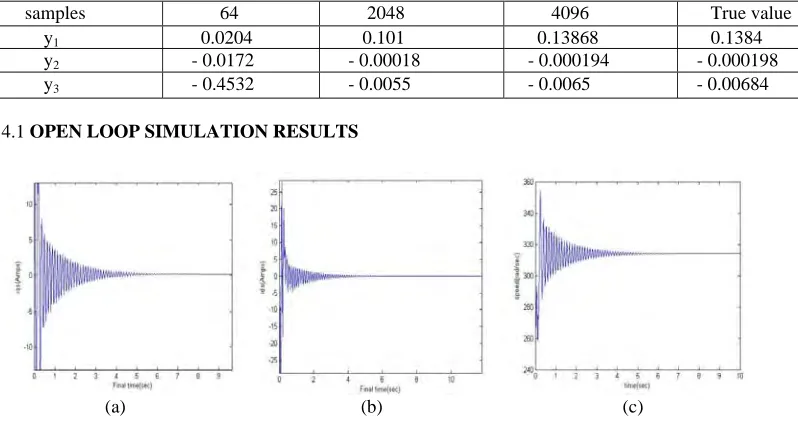
4.1 OPEN LOOP SIMULATION RESULTS
(a) (b) (c)
Fig.(1):Simulation results of open loop performance of the motor with a change in frequency from 45 to 50Hz at a constant load torque 5 N-m.
(a) (b) (c)
Fig.(2): simulation results of open loop performance of the motor with a change in load torque from Tl = 5 to 9N-m at a constant frequency
Fig.(3): Simulation result of open loop performance of the motor with inverter equations
5. RESULTS AND CONCLUSIONS
To estimates the parameters of PMSM with Hartley modulating function, we have written MATLAB code. HMF converts the non linear model equations into linear model equations by assuming all initial conditions are zero. It should be known that to observe the open loop behavior and physical parameter of the motor, the non linear model is simulated in MATLAB. Two cases are illustrated here. Figure (1) shows that the response of motor to sudden change in input frequency from 45 Hz to 50 Hz at a constant load torque Tl =5 N-m. Figure (2)
shows that the response of motor to sudden change in load torque from 5 N-m to 9 N-m at input frequency 50 Hz.Figure (3) shows that the response of open loop simulation of motor with inverter equations.
Permanent magnet synchronous motors have been modeled in d-q axes representation. A new technique based on Hartley modulating functions has been applied for estimation of parameters of Permanent magnet synchronous motors in the non linear model. Using the data obtained from open loop simulation, physical parameters such as stator resistance and inductances as well as mechanical parameters such as moment of inertia and viscous friction coefficient have been estimated with fair amount of accuracy. The use of a non linear model ensures that the technique can be used for determining the parameters of the system under all operating conditions. However, the non linear equations have been simplified by eliminating the inaccessible quantities, namely, damper winding currents in order to avoid complexity to perform convolutions on long data equations. The estimates have been found to be quite sensitive to the choice of sampling time and size.
REFERENCES
[1] K. Alice Mary, ‘Speed Control of An SPWM inverter Driven Non Linear PMSM Drive with Pole Placement Technique-11’, IEEE International conference on Electrical energy systems and power electronics in emerging economics ICEESPEEE 2009. SRM University, Chennai 16-17 April 2009 413-417
[2] K. Alice Mary, ‘Design performance of the speed control systems for inverter driven Nonlinear Permanent magnet synchronous motor using exact feedback linearization’, 1st
international conference on computer communications, control and information technology”,06-07-feb2009
[3] P. S. Bimbra, ‘Generalized theory of Electrical machines’, Khanna Publishers. [4] Paul C. Krause, ‘Analysis of Electrical Machinery and drive systems’, 2nd
edition, Wiley Inter science A John wiley and sons; INC Publications.
[5] R. Krishnan, ‘Electric motor drives: Modeling analysis and control’, Prentice Hall, 2001 edition.
[6] Mihai Comanescu, ‘Reduced order observers for Rotor Position Estimation of Nonsalient PMSM’, IEEE transactions, 2009.
[7] Jorge A. Solsona and Maria I, ‘A Nonlinear Reduced Order Observer for Permanent Magnet Synchronous Motors’, IEEE transactions, 2006.
[8] A. B .Dehkordi and M. Gole, ‘Permanent Magnet Synchronous Machine Model for real time simulation’, International conference on power systems transients, June 19-23, 2005.
[9] Jorge O. Estima and A. J. Marques Cardoso, ‘Performance Analysis of Permanent Magnet Synchronous motor drives under Inverter Fault Conditions’, International conference on Electrical Machines, 2008.
[10] Jorge O. Estima and A. J. Marques Cardoso, ‘Impact of Inverter Faults in the Overall Performance of Permanent Magnet Synchronous Motor Drives’, IEEE transactions, 2009.
[11] Khwaja M. Rahman and Silva Hiti, ‘Identification of Machine parameters of a Synchronous Motor’, IEEE transactions, 2003 [12] P. Brandstetter, P. Rech, and P. Simonik, ‘Sensorless Control of Permanent Magnet Synchronous Motor Using Luenberger Observer’,
PIERS Proceedings, Cambridge, USA, July 5-8, 2010.
[15] Jorge A. Solsona and Maria I, ‘Disturbance and Nonlinear Luenberger Observers for Estimating Mechanical Variables in Permanent Magnet Synchronous Motors Under Mechanical Parameters Uncertainties’, IEEE transactions, August 2003.
[16] Hyungbo Shim and Laurent Praly, ‘Remarks on equivalence between full order and reduced order nonlinear observers’, Conference on Decision and Control, December 2003.
[17] K. Alice Mary, A. Patra, N. K. De, ‘A Generalized Approach to the Design of the Speed Control system for Inverter-Driven Permanent Magnet Synchronous Motor’, IET-UK International Conference on Information and Communication Technology in Electrical Sciences (ICTES 2007), Dr. M.G.R. University, Chennai, Tamil Nadu, India. Dec. 20-22, 2007.
[18] Mihai Comanescu and Todd D. Batzel, ‘Full Order EMF Observer for PMSM Design, Analysis and Performance under Improper Speed Signal’, IEEE transactions, 2010.
[19] Junfeng Xu, Yinglei Xu, Jiangpin Xu, Jianghua Feng and Fengyan Wang, ‘Direct torque control of Permanent Magnet Synchronous Machines using Stator flux Full order State Observer, IEEE transactions, 2004.
[20] Khwaja M. Rahman and Silva Hiti, ‘Identification of Machine parameters of a Synchronous Motor’, IEEE transactions, 2003. [21] Jorge A. Solsona and Maria I, ‘A Nonlinear Reduced Order Observer for Permanent Magnet Synchronous Motors’, IEEE transactions,
2006.