R E S E A R C H
Open Access
High performance and low complexity
decoding light-weight video coding with
motion estimation and mode decision at
decoder
Ted Chih-Wei Lei
1*and Fan-Shuo Tseng
2Abstract
Light-weight video coding (LVC) follows distributed video coding (DVC) and designs to move computational complexity from the encoder to the decoder, thus making a low computational complexity encoder. In traditional video coding, the high computational complexity encoder algorithms, where motion estimation and mode
decision, are the main transferred objects. In order to alleviate the computational burden, the proposed architecture adopts the Partial Boundary Matching Algorithm (PBMA) and four flexible types of mode decision at the decoder; this circumvents the traditional use of motion estimation and mode decision at the encoder. In simulation, the proposed architecture, Padding Block-based LVC, not only outperforms the state-of-the-art DVC (DISCOVER) codec by up to 4~5 dB but also significantly decreases decoder complexity to approximately one hundred times lower than that of the DISCOVER codec.
Keywords:Light-weight video coding, Distributed video coding, Padding block-based light-weight video coding, Motion estimation at decoder, Mode decision at decoder
1 Introduction
Video coding involves a complementary pair of systems: a compressor (encoder) and a decompressor (decoder). The coding can then be devised to remove any redun-dancy in the temporal and spatial domains. Generally, two video coding types are typically considered: lossless and lossy coding. Lossy video coding involves motion compensation, transform and quantization processing, while lossless video coding entails entropy coding. In addition, lossy video coding is required for higher com-pression, since lossless video information only allows for moderate compression. The current standard compatible with the above algorithms has been developed to provide a high quality, low distortion, and low bit-rate transmis-sion. Compared with early proposed standards, the H.264/ AVC standard achieves up to a 50% improvement in bit-rate efficiency and is suitable for many applications, such
as web video downloads, video broadcasting, video on demand systems, and consumer electronics video prod-ucts. However, the above applications of H.264/AVC video coding are subject to numerous complicated loading prob-lems. For example, the video stream is only compressed once, but decoded many times. Typically, the encoder is five to ten times more complex than the decoder. Thus, in order to reduce computational loading at the encoder, the spirit ofDistributed Video Coding(DVC) is developed to implement a lower complexity level of video coding, shift-ing the complexity from the encoder to the decoder with-out reducing the video coding quality.
The fundamental concept of DVC is based on two sig-nificant information theorems: Slepian-Wolf (SW) [1] and Wyner-Ziv (WZ) [2]. The SW coding theorem is a lossless source coding, while the WZ coding theorem is a form of lossy source coding. DVC as defined in [3] must obey
these two information theorems; however, the
Light-weight Video Coding (LVC) does not follow the original DVC definition. LVC is only complies with the DVC spirit, and develops to implement a lower complexity level of * Correspondence:[email protected]
1The Electrical Engineering Department of National Sun Yat-sen University,
70 Lienhai Rd., Kaohsiung 80424, Taiwan, Republic of China Full list of author information is available at the end of the article
video encoding, shifting the complexity from the en-coder to the deen-coder. Based on these theorems, there exist three major groups for the development of DVC architectures: The Stanford DVC scheme [3], the Eur-ope DISCOVER (DIStributed COding for Video sER-vices) codec [4, 5] and the Berkeley PRISM (Power-efficient, Robust, hIgh-compression, Syndrome-based Multimedia coding) paradigm [6]. Basically, the DVC scheme proposed by Stanford works at the frame level and adopts turbo code-based SW coding; this is character-ized by a feedback channel performing rate control at the decoder. The DISCOVER video codec by Europe is actu-ally an extension of the Stanford DVC scheme, which is able to significantly improve performance. The main con-cept of DISCOVER is to flexibly adjust the GOP-sized se-lection, and it adopts a low-density parity check accumulator (LDPCA) coding scheme with an 8 b Cyclic Redundancy Checksum (CRC) at the encoder. At the de-coder, a bi-directional motion estimation is conducted with spatial smoothing (BiMESS) in order to obtain high quality side information (SI), while motion search is adopted to increase the sub-pixel precision method for BiMESS. The PRISM codec by Berkeley is conducted at the block level and uses the syndrome code-based SW coding. It is characterized by an encoder side rate control-ler based on the availability of a reference frame.
In addition, Taiwan University has proposed a hybrid DVC (hybrid distributed video coding with frame level coding mode selection) architecture [7, 8], which is an extension of the state-of-the-art DVC (DISCOVER) codec. This architecture is beneficial, adding minor com-putational complexity, and integrating entropy coding into WZ frame encoding, while conventional DVC only uses the channel coding function. Thus, the inclusion of entropy coding not only slightly increases complexity but also improves performance.
Currently, DVC has not reached the performance level of classical inter-frame coding. This is in part due to the quality of the side information (SI), which has a strong impact on the final rate-distortion (RD) performance. In order to produce the SI, DISCOVER uses the Motion-Compensated Temporal Interpolation (MCTI) [9]
tech-nique. In [10–12], the authors presented DVC schemes
that perform the motion estimation both at the encoder and decoder. In [10], the authors propose a pixel-domain DVC scheme, which consists of combining low complexity bit plane motion estimation at the encoder, with motion-compensated frame interpolation at the decoder. The improvements are shown for sequences containing fast and complex motion. In [11], a DVC scheme is presented in which the task of motion estima-tion is performed both at the encoder and decoder. The results have shown that the cooperation of the encoder and decoder can reduce the overall computational
complexity while improving coding efficiency. Finally, [12] proposed combining the global and local motion estimations at the encoder while the motion estimation and compensation are performed both at the encoder and decoder.
Conversely, in [13], the local motion estimation is only performed at the decoder, while the global motion param-eters are estimated at the encoder using a scale-invariant feature transform (SIFT) [14] algorithm. It is important to note that the encoding complexity is kept low. The global parameters are sent to the decoder to estimate the global motion compensation (GMC) SI, and the combination between the GMC SI and MCTI SI is made at the de-coder. This approach consists of combining global and local motion compensation at the decoder. The parame-ters of the global motion are estimated at the encoder using SIFT features. These estimated parameters are then sent to the decoder in order to generate a globally motion-compensated SI. Conversely, a locally motion compensated SI is generated at the decoder based on the MCTI of neighboring reference frames. Moreover, an improved fusion of global and local SI during the decod-ing process is achieved usdecod-ing the partially decoded WZ frames and decoded reference frames. The method pro-posed in [13] significantly improves the quality of the SI, especially for sequences containing high global motion.
Another DVC paradigm is different to the extension of Stanford DVC scheme and DISCOVER codec. In [15], a dynamic skip mode threshold is proposed, based on PRISM [6] architecture for higher coding efficiency. In the encoder of the classifier module, while the skip mode threshold is a dynamic value different from the original PRISM with fixed value. In the encoder of the syndrome encoding module, the original PRISM archi-tecture, block coefficients in the least significant part were coded in a 4-tuple symbol {Last, Run, Depth, Path}, while a 3-tuple symbol {Last, Run, Path} was applied in [15] with depth substituted by class type. The key parts of the decoder are the motion search loop, syndrome decoding, and hash checking. First, the motion search is performed at the decoder in order to find suitable pre-dictors. Also, the syndrome decoding module generates side information candidates by searching through previ-ously decoded frames. In addition, the hash checking module checks the correctness of decoded blocks, and the process is repeated until the decoded block passes hash checking, indicating successful decoding.
motion search module integrated with the classifier for a more accurate rate control, and [15] outperforms other feedback channel free architectures with only a slight increase in encoder complexity. In a feedback-channel-free DVC architecture, the encoder plays a crucial role for coding performance since the bitrate and the quality are determined at the encoder while the decoder is re-sponsible for regular decoding procedures. In light of this, [16] proposes an enhanced classifier architecture in the encoder to further improve the coding performance. However, the [15] can attain the class type and depth distribution of transform coefficients. Also, [16] applies three-step search (3SS) at the encoder of the classifier module, and the 3SS estimates the correlation noise be-tween the current block and the best predictor at the de-coder more precisely. The new classifier module exploits the available predictor at the encoder and performs clas-sification to achieve a more accurate rate control. The classifier for class type and depth distribution of trans-form coefficients is retrained offline.
In fact, DVC avoids the computationally intensive temporal prediction loop at the encoder, by shifting the exploitation of the temporal redundancy to the decoder. This is a significant advantage in a wide range of emer-ging application scenarios, including wireless video cam-eras, wireless low-power surveillance, video conferencing with mobile devices, disposable camera, high pollution medical cameras, and visual sensor networks.
DVC effectively reduces the complexity of the encoder, but it also causes some problems. The two main disadvan-tages are poor performanceand high decoder complexity. The cause of poor DVC performance is the DVC en-coder’s use of only H.264/AVC intra frame coding. This computational complexity is 5 to 10 times lower than that of the traditional H.264/AVC inter frame coding. In addition, conventional DVC has only half the complexity of H.264/AVC intra frame coding between key and WZ frames. Therefore, the usage complexity of the DVC en-coder is almost 10 to 20 times lower than the conventional H.264/AVC video coding. It is therefore difficult to achieve the same performance with current traditional video coding. To date, DVC rate distortion (RD) perform-ance remains between H.264/AVC intra and inter frame with no motion video coding. In order to solve this diffi-cult problem, the general solution is the addition of some efficient algorithm in the DVC encoder to improve per-formance. However, this will mean that the encoder will no longer operate with the original intra frame video cod-ing, but rather with partial inter frame video coding. This will, of course, increase DVC encoder complexity. An-other significant problem faced by DVC is high decoding complexity; this problem leads to difficulties in performing real-time video processing. This is the result of the time-consuming nature of the error-correcting coding of
recursive systematic convolutional (RSC) decoding for LDPCA decoders. In [5], it is shown that over 90% of the computational complexity at the LDPCA decoder is made up of decoding time. Other challenges also remain to be solved in traditional DVC, such as the feedback channel problem. It is clear then that DVC encoder complexity must be reduced, the rate control should be transferred to the decoder, and it must be ensured that that the bidirec-tional communication channel is available. Many studies have therefore attempted to move the rate control from the decoder back to the encoder and to eliminate the feed-back channel problem. Moreover, the encoder requires a larger frame buffer, and in flexible GOP size, this may result in increased hardware costs, especially in slow mo-tion video sequences. The decoder may also encounter the block effect due to the fact that some DVC encoder designs use block-based video coding. Chrominance has no significant effect, and only luminance is considered for processing. Finally, there is no unified DVC standard, which increases the difficulty of making a DVC extension. In summary, then, DVC cannot be widely adopted in many applications due to its poor performance, decoder complexity, and the abovementioned shortcomings.
The proposed LVC scheme, Padding Block-based
Light-weight Video Coding (PB-based LVC), solves the
two main DVC drawbacks: poor performance and high
decoder complexity. Since motion estimation takes up a large part of the computational loading in traditional
video coding, the propose method uses aPartial
Bound-ary Matching Algorithm(PBMA) as the motion estima-tion at the decoder to replace the moestima-tion estimaestima-tion at the encoder. Also another high complexity algorithm, mode decision, needs transfer from the encoder to the decoder through four different flexible modes. This shift-ing of mode decision to the decoder is a novel move. The proposed scheme therefore differs from the above types of traditional DVC architectures and does not use the traditional DVC frame level design and error correc-tion coding (e.g., Turbo, BCH, or LDPC coding) as the WZ frame coding scheme, but rather uses a block level design and padding-based algorithm.
The remainder of this paper is organized as follows. Section 2 explains DVC in network systems. Section 3 introduces the background (e.g., the traditional motion estimation and mode decision) and methodology (e.g., the PBMA and mode decision at the decoder). Section 4 describes the proposed PB-based LVC architecture. Section 5 discusses the experimental results. Section 6 draws conclusions.
2 DVC in a network configuration
would only be useful in a small number of fields such as wireless video surveillance systems. If, however, DVC were to become applicable to networks, then its poten-tial applications would be very widespread. The descrip-tion of a tradidescrip-tional video network system and a DVC network system are both as follows.
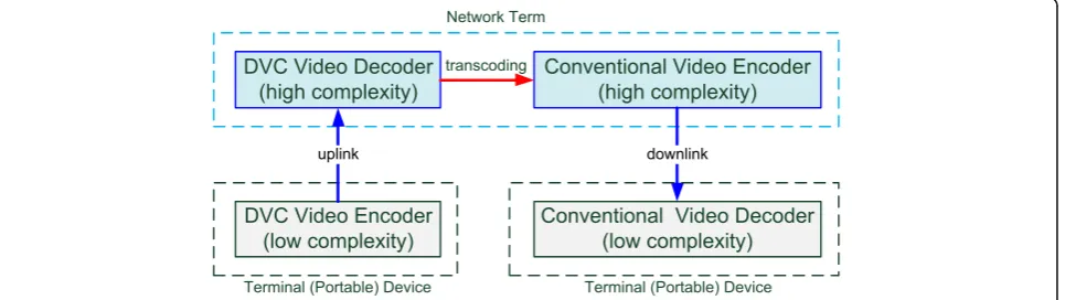
A traditional video transmission network is a store-and-forward network, where video data flow packets are forwarded hop-by-hop. The content of the video coding data flow is not essentially modified in the network term and transferred directly from the source end to the ter-minal end. Therefore, in traditional network
architec-ture, the implementation of video encoding and
decoding must take place on the terminal equipment without any additional processing in the network term. Thus, the computational loading of all video coding must be completed at the terminal devices. These results are in the high cost of wireless video surveillance, or the need for expensive video compression encoder chips (e.g., ITU-T H.26x and ISO/IEC MPEG-x) [17, 18] on commercial mobile phones with camera functions.
In order to effectively reduce the cost of a video trans-mission network at the encoder, early proposed DVC
[3–8] schemes suggested a network solution. In these
schemes, the primary aim is to transfer computational complexity from the terminal device to the network term. The advantage of this architecture is that it inher-ently transfers the complexity to the network term be-cause it uses the DVC scheme in the uplink and a traditional video coding scheme in the downlink. In this network architecture, the computational loading of the terminal device can be reduced as compared to trad-itional video networks, as shown in Fig. 1.
3 Related works and main technologies
In the early stages of DVC development, the video cod-ing standard was based on H.263+, which aimed to de-velop the motion estimation algorithm. The high performance motion estimation algorithm has a high complexity encoding, which can be considered as the
transfer target for DVC. Today, more advanced video coding standards have been proposed. Another out-standing algorithm, mode decision, which flexibly encodes picture blocks in exchange for improving the encoding efficiency, is able to increase the encoding complexity. Mode decision is thus another transfer tar-get. For this reason, the proposed PB-based LVC miti-gates the encoder complexity with motion estimation and mode decision. The main idea is that the proposed scheme only adopts zero motion searching, and uses less inter frame encoding. Because motion estimation is not used, a low complexity encoder is expected. At the decoder, the proposed scheme utilizes PBMA and mode decision with decoder algorithms with high performance and low computational complexity inter frame decoding as compared to traditional DVC schemes.
This section contains two subsections: motion estima-tion [17] and mode decision [18]. Tradiestima-tional moestima-tion estimation at the encoder is discussed in Subsection 3.1, and the proposed primary function of motion estimation at the decoder, PBMA, is introduced in Subsection 3.2. Conventional mode decision at the encoder is explained in Subsection 3.3. Finally, the proposed enhanced func-tion mode decision process at the decoder is demon-strated in Subsection 3.4.
3.1 Traditional motion estimation at encoder in H.264/ AVC video coding
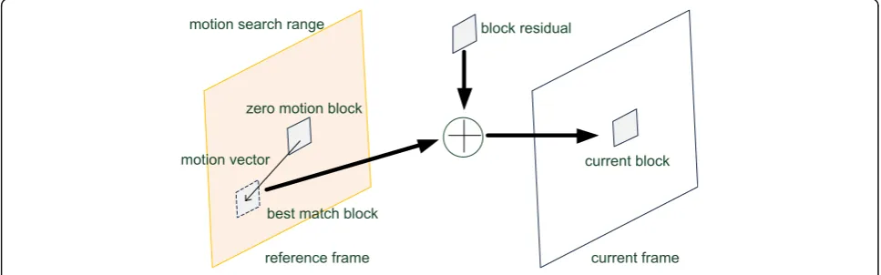
All conventional video coding standards use block type motion estimation coding, which is a kind of inter frame motion compensation prediction used for redu-cing temporal redundancy. The conventional motion estimation operation uses the block of a current frame to search for a best predictor block (best match block) in the search range of the reference frame, where the motion vector represents the best match block position
with a zero motion block. The rate distortion
optimization (RDO) function—a general assessment
method used to achieve the best mode between
performance and rate of data flow—of the motion esti-mation can be expressed as follows:
JME m!; FrefjλME
¼SAD s; c Fref; m!
þ λME‧ R m!−!p
þR Fð refÞ
ð1Þ
where ME denotes motion estimation, m!=(mx, my)T
= (dx, dy)T is the motion vector (T is a transpose matrix), Fref is the reference frame, andλME is the
mo-tion estimamo-tion Lagrange multiplier. The SAD funcmo-tion is the Sum of Absolute Differences, while s and c are the original reference video signals. R(m!−!p) represents the bit coding for the motion vector, and R(Fref) is the bit
coding for the reference frame. In motion estimation, a motion vector is selected by the SAD, and the SAD is computed as:
SAD s;c Fref;!m
¼XNx¼;N1;y¼1js xð ; yÞ−c xð −dx; y−dyÞj
ð2Þ
where s and c are the original reference video signal, Fref
is the reference frame, m! is the motion vector, N is block size, (x,y) is a pixel of the reference frame, and (dx,dy) indicates the motion vector. However, encoder complexity is caused by the accumulative additions in-volved in motion search. Therefore, Eq. (2) shows that the encoder incurs high complication encoder loading with motion estimation, as depicted in Fig.2.
3.2 Motion estimation at decoder with PBMA
The primary aim of LVC is to transfer certain compli-cated operations from the encoder to the decoder. Dur-ing the transfer, the decodDur-ing performance will not be severely degraded and will remain within a tolerable range. The high performance motion estimation at the encoder of the transitional video coding is essentially a high computational complexity algorithm. However, the proposed scheme does not utilize motion estimation at
the encoder. This significantly reduces the encoding complexity, and without high efficiency motion estima-tion, the performance may be degraded outside the pre-defined tolerable range. The proposed scheme uses PBMA to replace the function of motion estimation, and PBMA can thus demonstrate performance that ap-proaches motion estimation at the encoder. The pro-posed PBMA algorithm is detailed as follows:
PBMupregionðdx;dyÞ ¼ X
X¼X0−b
X0þN−1
jPcurrðX;Y0−bÞ
−Pref Xð þdx;Y0−bþdyÞj
þ X
X¼X0−b
X0þN−1
jPcurrðX;Y0−bþ1Þ
−Pref Xð þdx;Y0−bþ1þdyÞj
þ X
X¼X0−b
X0þN−1
jPcurrðX;Y0−bþ2Þ
−Pref Xð þdx;Y0−bþ2þdyÞj •••
þ X
X¼X0−b
X0þN−1
jPcurrðX;Y0−1Þ
−Pref Xð þdx;Y0−1þdyÞj ð3Þ
, and
PBMleftregionðdx;dyÞ ¼ X
Y¼Y0
Y0þN−1
jPcurrðX0−b;YÞ
−Pref Xð 0−bþdx;YþdyÞj
þX
Y¼Y0
Y0þN−1
jPcurrðX0−bþ1;YÞ
−Pref Xð 0−bþ1þdx;YþdyÞj
þX
Y¼Y0
Y0þN−1
jPcurrðX0−bþ2;YÞ
−Pref Xð 0−bþ2þdx;YþdyÞj •••
þX
Y¼Y0
Y0þN−1
jPcurrðX0−1;YÞ
−Pref Xð 0−1þdx;YþdyÞj
ð4Þ
, then
PBM dxð ;dyÞ ¼PBMupregionðdx;dyÞ
þ PBMleftregionðdx;dyÞ ð5Þ
where PBM(dx,dy), PBM_up_region(dx,dy), and PBM_left_region
(dx,dy) are the total, upper region, and left side SAD of PBMA and (dx,dy) is a candidate motion vector. Pcurr(X,Y)
and Pref(X,Y) denote the pixel value of current and
refer-ence frame. (X0, Y0) is the position of the skipped block.
Here, N is block size and b is the condition size of the tem-plate neighbor region.
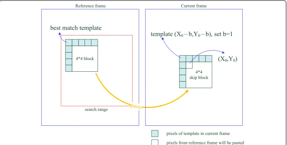
PBMA is modified from the Boundary Matching Algo-rithm (BMA) [19]. BMA is a kind of error concealment method and mainly uses the boundary pixels of loose blocks to find the best matching block in the search range of a reference frame. The steps involved in BMA are as fol-lows: First, the BMA template is the neighborhood pixel of the loose block. Second, as in motion estimation, the candi-date block is selected from the search range in the refer-ence frame. Third, in the search range, each candidate block neighborhood pixel is compared with the template. Fourth, the candidate block, which is most similar to the template, is the best matching block. Finally, the best matching block is pasted back into the current frame. The major difference between PBMA and BMA is that BMA uses all adjacent pixels of the block as a template, whereas PBMA only uses partial adjacent pixels (in general, only two adjacent pixels) because the decoding block of adjacent pixels has not been decoded. Thus, only the partial block adjacent pixels can be used. As shown in Fig. 3, each small block (white and light blue colors) represents one pixel.
3.3 Conventional mode decision at encoder in H.264/AVC video coding
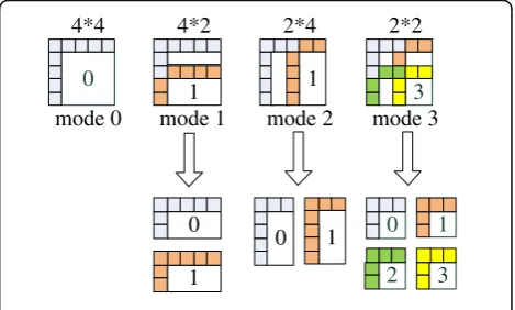
Conventional video coding can improve block selection flexibility as well as the ratio of block comparison error
in the mode decision algorithm; eight different block mode selections are considered, e.g., 16 × 16, 16 × 8, 8 × 16, 8 × 8, 8 × 4, 4 × 8, and 4 × 4. The use of more block selections with differing flexibility macroblock types re-garding the motion estimation and motion compensa-tion will significantly enhance performance but will also increase the computational complexity at the encoder. In addition, the mode decision according to the frame complex generally uses different block modes, where the complex part uses smaller macroblocks, and the smooth part represents larger macroblocks, as shown in Fig. 4.
The RDO function of mode decision is defined as follows:
JMD s;c;MDjλMD
¼SSD sð ;c;MDÞþλMD‧R sð ;c;MDÞ ð6Þ
where s and c are the original reference video signals, MD denotes mode decision, and λMD is the mode
deci-sion Lagrange multiplier. SSD is the Sum of Square Dif-ference between the original frame and the reDif-ference frame. R(s,c,MD) represents the bit coding between the original frame and the reference frame. In mode deci-sion, the luminance SSD is defined as:
SSD sð ;c;MDÞ ¼XN;N
x¼1;y¼1js xð ; yÞ−c xð ; yÞj
2 ð
7Þ
where s and c are the original reference video signals, MD denotes mode decision, N is block size, and (x,y) is a pixel in the reference frame. Similarly, mode selection encounters the tradeoff between performance and
complexity issues, as with the traditional motion estima-tion algorithm.
3.4 Mode decision at decoder with PB-based LVC
Although mode decision performance can be signifi-cantly enhanced in conventional video coding, the com-putational complexity at the encoder will remain high. Therefore, the proposed scheme aims to shift mode decision to the decoder; the primary goal is to use its high performance characteristics to address the trad-itional DVC low performance problem. The proposed scheme, with mode decision at the decoder, largely strengthens PBMA which is a motion estimation at the decoder algorithm, and effectively improves performance over using PBMA without mode decision at the decoder. This is the first time mode decision has been shifted to the decoder. In addition, the proposed scheme is a low-complexity mode decision at the decoder along with traditional high-complexity decoder DVC solutions. The proposed mode decision at the decoder has four different modes: modes 0 to 3, where the mode (block type) is chosen from the candidate type set {4 × 4, 4 × 2, 2 × 4, 2 × 2}. Apart from mode 0, the other modes may fail to be completed because neighborhood blocks have not been decoded. The selection method of best block types involves calculating the mean addition differential (MAD) by neighborhood pixels. Next, the best type block is pasted back in order, and mode decision at the decoder is completed, as depicted in Fig. 5. Therefore, the MAD is defined as:
MAD xð ;yÞ ¼SAD xð ;yÞ=N2 ð8Þ
where SAD(x,y) is the pixel value of the Sum of Absolute Differences and N is the block size.
4 Padding block-based light-weight video coding
The PB-based LVC architecture is comprised of three parts at the encoder: the classifier, skip block mask and rearrangement (including the skip block record table),
and the conventional intra frame encoder, depicted in the Fig. 6. Initially, the classifier can be divided into SAD and DC classifiers. The SAD classifier is used to deter-mine zero motion blocks. After the SAD classifier, the DC (Direct Current) classifier is carried forward to re-place the search of low motion blocks for motion esti-mation (DC value is generally used in the DC coefficient of DCT (discrete cosine transform)). Therefore, the clas-sifier is only suitable for recognizing zero and low mo-tion blocks and is unsuitable for other cases, especially in high motion blocks. Two functions, the skip block mask and rearrangement, are based on the results of the classifier. If the classification value is smaller than the setting threshold, the block will be skipped, and the DC value of the block will be filled in; otherwise, the block will be retained and sent to the conventional intra frame encoder after further transferring the video stream to the decoder. The skip blocks with DC fill in function have better performance than without DC fill in func-tion. Finally, the skipped blocks’ data are saved in the skip block record table with three states (non-skip blocks, SAD classification blocks, and DC classification blocks). The encoded video stream and record table are then output to the decoder, respectively.
Fig. 4Mode types in mode decision at encoder with conventional H.264/AVC video coding (the number within each block indicating the coding order)
0
4*4
mode 0
1 mode 1
4*2
0
1
1 2*4
mode 2
0 1
2*2
mode 3
3
0 1
2 3
pixels of template in candidate block neighborhood
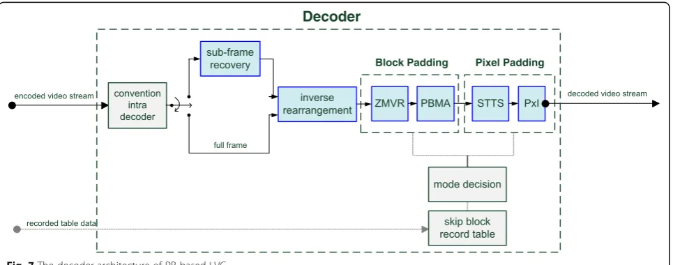
The decoder consists of three main parts, including the conventional intra frame decoder, the block pad-ding and the pixel padpad-ding, shown in the Fig. 7. The conventional intra frame decoder first decodes the video stream from the encoder. After decoding, the block padding is used to pad blocks and is divided into Zero Motion Vector Replacement (ZMVR) and Partial Boundary Matching Algorithm (PBMA) to re-place the high complexity motion estimation algo-rithm at the encoder. ZMVR and PBMA acquire the skip block record table information from the skipped blocks of the encoder and then pad zero and low mo-tion blocks with four flexible block mode decision. The PBMA algorithm is employed to select the best matching block by neighbor pixel data around the skipped block and searches candidate blocks as with motion estimation in the setting search range, after finding the best matched block and then padding it from the reference frame. After block padding, the remaining unrecovered blocks use pixel padding. Pixel padding consists of Spatial Temporal Texture
Synthesis (STTS) and Pixel Interpolation (PxI). STTS is an efficient approach not only for image recon-struction technology but also for video compression. Of course, STTS finds the best matched pixel with four neighborhood templates from the appropriate search range. The proposed STTS algorithm not only uses spatial frames as a search range but also uses temporal frames. Finally, the PxI is used to complete the padding for all remaining unrecovered pixels after the above algorithm. The PxI utilizes image inpainting technology to recover pixels.
4.1 Encoder
The proposed scheme adopts a GOP frame coding struc-ture, as found in traditional video coding. Herein, the first frame is encoded with the traditional intra frame encoding, and the other frames function using skip block encoding. With this procedure, as with the traditional video coding results, intra frame coding prevents the entire GOP frame from distorting.
Fig. 6The encoder architecture of PB-based LVC
4.1.1 Classifier
The functional block, classifier, includes the SAD and DC classifiers. These classifiers are used to identify the zero motion block and the low motion block; therefore, this design is not suitable for determining the medium and high motion blocks. The SAD classifier could be used to determine SAD (0) (the zero motion block). The formula is defined as follows:
SADðx; yÞ ¼
X
x
¼
x
0
x0þN−1
X
y¼y0 y0þN−1
Bcurrðx; yÞ−Brefðx; yÞ
ð9Þ
where SAD(x,y) is the SAD value between the current and reference block, Nis block size, (x0,y0) are the co-ordinates of the current block, Bcurr(x, y) and Bref(x, y)
are the pixel value of the current and reference blocks. After the SAD classifier, the DC classifier is performed and the DC value (average value) is evaluated. This is calculated as
AVG xð ;yÞ ¼AVGcurrðx; yÞ‐AVGrefðx; yÞ
¼N−2
X
x
¼
x
0
x0þN−1
X
y¼y0 y0þN−1
Bcurrðx; yÞ
−
X
x
¼
x
0
x0þN−1
X
y¼y0 y0þN−1
Brefðx; yÞ
ð10Þ
where AVGcurr(x, y) and AVGref(x, y) are the DC values
(average value) of the current and reference blocks, respectively; N is the block size, (x0, y0) is the pixel position of the current block, Bcurr(x,y) and Bref(x,y) are
pixel values of the current and reference blocks. This average value helps to easily search for low motion blocks when the low motion block partially overlaps pixels of the co-located block. Therefore, with the classifier-block, it is easy to see that the proposed LVC encoder adopts partial inter frame coding, rather than the pure intra frame coding adopted by trad-itional DVC.
4.1.2 Skip block mask and rearrangement
The functional block, skip block mask, first masks all skip blocks with the results obtained from the classifier-block and saves the information of the skip blocks to the skip block record table. The mask condition is designed as
thsad¼SADðx; yÞ; thdc¼AVGðx; yÞ ð11Þ
masksadð Þ ¼i 10;; thotherwisesadð Þ≤i τ1
;
maskdcð Þ ¼i
1; thdcð Þ≤i τ2 0; otherwise
ð12Þ
where th
sadand thdcare the SAD(x,y) and AVG(x,y)
dif-ferential values from Eqs. (9) and (10), respectively. Here, mask(i) is set to 1, and if the thsad and thdc of
block i are below the thresholds τ1 and τ2, the block is
skipped. Otherwise, it is assumed to be a non-skip block. After the skip block function, the rearrangement-block function will rearrange reserve (non-skip) blocks by a new order, which concentrates non-skipped blocks to-gether. As a result, it is easy to distinguish skip blocks and non-skip blocks in a frame.
4.1.3 Sub-framing
After the rearrangement-block is the sub-framing-block, which is a half video frame processing, if this frame skips over 50% of the blocks. Otherwise, if the frame skips less than 50% of the blocks, full video frame is retained. From this, the frame size transmitted to the decoder can be greatly reduced in slow motion video sequences. However, if the frame in the high motion video se-quences is insufficiently conditioned, it will send a full frame to the next functional block.
4.1.4 Conventional intra frame encoder
The functional block of the conventional intra frame en-coder, such as H.263+, H.264/AVC, H.265/HEVC, MPEG-2 and MPEG-4 intra frame coding, and even JPEG, JPEG-2000, all depend on the range of suggestion. Therefore, high-performance H.264/AVC main profile and H.265/HEVE main profile level 1 intra frame video coding is adopted in this paper. In addition, since the rate control issue arises from the feedback channel prob-lem, the proposed scheme includes a rate control at the encoder, which differs fundamentally from conventional DVC with the rate control at the decoder.
4.1.5 Skip block record table
As described above, this record table needs only 2 b to store information per block, e.g., (0, 0) stands for non-skip block, (1, 0) refers to skip blocks by SAD classifier, (0, 1) is skip blocks by DC classifier, and (1, 1) means reserved.
4.2 Decoder
4.2.1 Conventional intra frame decoder
The proposed scheme uses H.264/AVC and H.265/ HEVC video decoding directly and can be used to detect most of the parameters from the encoder automatically; this excludes skip block information.
4.2.2 Sub-frame recovery
If the encoder uses a sub-framing function, the decoder should recover it to a full fame; if not, skip this step.
4.2.3 Inverse rearrangement
The functional block, inverse rearrangement, is arranged in order of the blocks. The blocks’positions are recov-ered to form the original video frame status.
4.2.4 ZMVR
The ZMVR is used to directly paste the zero motion blocks from the co-located block of the reference (previous) frame and according to the information from the skip block record table. However, sometimes this is unsatisfactory because some non-skip blocks have not been reconstructed from the reference frame, and the non-reconstructed blocks will thus continue to be processed in the next PBMA-block.
4.2.5 PBMA
The PBMA function, which is a boundary matching algorithm, primarily uses the boundary pixels of loose blocks to find the best match blocks in the search range of the reference frame. The steps of PBMA are as follows: First, the PBMA template is the upper and left hand side neighborhood pixel of the lose block. Second, the candi-date block is selected from the search range in the refer-ence frame. Third, each candidate block’s neighborhood pixel is compared with the template in the search range. Fourth, the candidate block, which is most similar to the template, is the best match block. Finally, the best match block is pasted back into the current frame. For simplicity, the calculation related to PBMA is defined as follows:
PBMupregionðdx;dyÞ ¼ X
X¼X0−1
X0þN−1
jPcurrðX;Y0−1Þ
−PrefðXþdx;Y0−1þdyÞj ð13Þ
and
PBMleftregionðdx;dyÞ ¼
X
Y¼Y0
Y0þN−1
jPcurrðX0−1;YÞ
−PrefðX0−1þdx;YþdyÞj ð14Þ
, and finally
PBM dxð ;dyÞ ¼PBMupregionðdx;dyÞ þ PBMleftregionðdx;dyÞ
ð15Þ
where Eqs. (13), (14), and (15) are defined similar to Eqs. (3), (4), and (5) above, except b is set to 1.
4.2.6 STTS
The STTS function is a kind of texture synthesis algo-rithm and differs from the conventional texture synthesis which applies the spatial domain only. However, STTS uses the spatial frame and refers to the temporal frame. Although this will increase complexity, performance is en-hanced as well. Spatial texture synthesis [20, 21] is one of the more efficient approaches used to reconstruct a large digital image from a small digital sample image in conven-tional image processing. This is done by utilizing its struc-tural content. Thus, the proposed scheme uses this algorithm to implement the pixel padding.
After the block padding function, most blocks have been recovered, and only a few blocks need to be reconstructed by pixel padding. STTS adopts 8-neighborhoods as a search range at the decoder. Finding the best match of the current pixel involves using the template block on the four sides of each individual current pixel; the template is on the upper, lower, left, and right, respectively. Then, the best match of the template block in the search range is found. Finally, if the candidate pixel is selected, the candi-date pixel is pasted to recover it, as depicted in Fig. 8.
4.2.7 PxI
The functional block, PxI, utilizes pixel interpolation to reconstruct pixels in the current frame. The PxI-block can use any subjection interpolation algorithm and uses the average value of 4-neighborhoods pixels to complete unrecovered pixels.
4.2.8 Skip block record table
The function, skip block record table, is based on the table from the encoder. This table is able to support the best decoding information.
4.3 Enhance function
The proposed enhance function includes the following:
4.3.1 Backward video sequence procedure
4.3.2 Mode decision at decoder
As mentioned above, mode decision at the decoder pri-marily enhances the PBMA function in block padding, because the PBMA only processes the {4 × 4} blocks. Mode decision at the decoder then increases different block sizes for template matching. The calculation is the same as in conventional video coding and uses MAD to distinguish different block sizes for different modes. The departure from traditional video coding is that the MAD value cannot be calculated for each mode, where the minimum value is selected as the best mode. It is made in order of the candidate set {4 × 4, 4 × 2, 2 × 4, 2 × 2}. If decoding cannot be performed for the last mode block, the next mode cannot be decoded. Thus, only decoded modes can be used for a comparison, and the minimum MAD value is selected as the best block.
4.3.3 Remaining available enhancement functions
There are still more available enhancement functions which could be used in the PB-based LVC, e.g., mutual Fig. 8The STTS withleft handside template
bi-directional frame coding at the decoder, multiple ref-erence frame coding at the decoder, sub-pixel motion search at the decoder for PBMA ,and a de-blocking filter for block based LVC. The above subjection enhancement functions can be applied as effective methods for im-proving PB-based LVC.
5 Experiment results
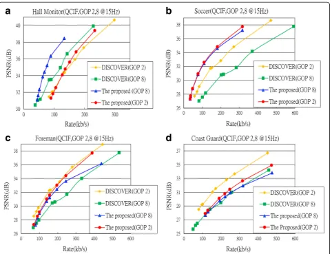
In the experiments, the RD performance and computa-tion time of the proposed LVC parameters are compared with those of the state-of-the-art DISCOVER codec, which is a typical DVC architecture, and most of the lit-erature entries selected are compared with it.
The RD performance of the proposed scheme is com-pared with that of the DISCOVER codec; therefore, all parameters follow DISCOVER, e.g., JM reference software, and the main profile is used to compare the PSNR of lu-minance (Y) without comparison with chrolu-minance (U, V) levels. It is assumed that the channel is free, frame rate is 15Hz, and quantization parameters QPs and QI are identical with those of DISCOVER. GOP length is 2 and 8, and the total number of frames is 150. Four general video test sequences, “Hall Monitor,” “Foreman,” “Soccer,” and
“Coast Guard,”are selected, where the Hall Monitor, Fore-man, and Soccer video test sequences are low, medium, and high activity video test sequences, respectively. Not-ably, the Coast Guard sequence is a significant one.
In the context of computational complexity, in order to avoid the difference in execution time for different platforms (CPU time), the ratio against H.264/AVC intra frame coding is used instead of a comparison of execu-tion time directly. Here, the personal computers (PC) associated with Intel Pentium dual-core CPU processor at 1.3 GHz and 4 GB RAM at 1.3 GHz are installed with the Microsoft Windows 7 64-b operating system.
5.1 RD performance
Overall, the proposed scheme’s performance (red and
blue line) is better than that of DISCOVER (orange and green line) in most video test sequences, except Coast Guard as it is a significant video test sequence and very suited for the DISCOVER codec; thus, surpassing its ability is not easily accomplished. In GOP 8, the
pro-posed scheme’s performance (blue line) is better than
that of DISCOVER. This is different in Coast Guard as the proposed scheme exhibits a loss of performance. But
in GOP 2, the proposed scheme’s (red line) performance is compared with that of DISCOVER in most video test sequences. Notably, Coast Guard and Soccer have been polarized. The proposed scheme’s performance for Coast Guard is lower than that of DISCOVER and is 2 dB.
However, the proposed scheme’s performance for Soccer
is higher than that of DISCOVER at 3 to 4 dB. The per-formance for Hall Monitor and Foreman is comparable with that of the DISCOVER codec. Conclusions regard-ing performance suggest that the proposed scheme is better than DISCOVER in GOP 8 but is comparable with DISCOVER in GOP 2, as seen in Fig. 9.
From this result, it is clear that the proposed scheme is more advantages, since in all types of video test sequences, even low motion or high motion video sequences, the pro-posed scheme’s performance remains consistent at a cer-tain level. Unlike traditional DVCs that only perform well under certain beneficial video test sequences, the pro-posed scheme can consistently exhibit improved perform-ance. However, in some disadvantageous video test sequences, e.g., DISCOVER codec in Soccer, its perform-ance will obviously become poor. In addition, the pro-posed scheme exhibits more stable performance and a
small difference in different GOP length. These two ad-vantages cannot be achieved with traditional DVCs.
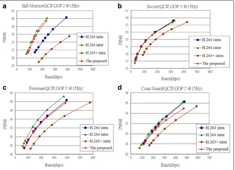
In addition to comparison with the DISCOVER codec, the proposed scheme must also be compared with trad-itional video coding, e.g., H.264/AVC and H.263+ video coding standard. This comparison more clearly shows the superiority of the proposed scheme. Thus, H.264/AVC intra, H.264/AVC inter with no motion, and H.263+ are three standards chosen for comparison. Overall, the pro-posed scheme’s performance is better than that of H.263+ and close to that of H.264/AVC, and from the curve, it can be seen that the proposed scheme’s performance ap-proaches the level of H.264/AVC inter with no motion.
In GOP 2, Hall monitor and Soccer, the proposed scheme’s curve (red line) is closer to H.264/AVC inter; with traditional DVC contrast, most DVC solutions could not simultaneously result in such good performance between these two video test sequences. However, the proposed
scheme’s performance with Foreman and Coast Guard is
closer to and slightly lower than H.264/AVC intra. There-fore, it is regarded as a fairly good performance.
In GOP 8, the performance is the same as in GOP 2 for the four video test sequences. Therefore, from the
results of Figs. 10 and 11, it is clear that the DVCs’ per-formance is lower than that of the traditional H.264/AVC video coding. This is because the usage of DVC encoder complexity is lower than the conventional H.264/AVC video coding by almost 10 to 20 times. Thus, it is very dif-ficult to attain the same level of performance at this stage. Of course, this also clearly highlights the dilemma faced in current DVC development: because computational com-putation at the encoder is reduced too much, the perform-ance is still between H.264/AVC intra and inter with no motion, and it is difficult to improve on this.
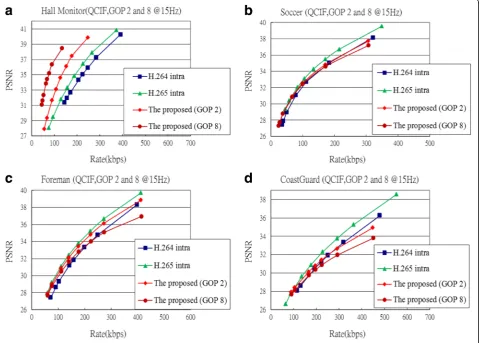
Furthermore, in order to prove that the proposed could still maintain the same situation in the H.265/ HEVC standard, same four video testing sequences are selected for comparison, and the PB-based LVC uses H.265/HEVC intra as its conventional intra frame encoder and decoder. In GOP length 2 and 8, the per-formance is the same with the H.264/AVC standard for the all video sequences. Therefore, from the results of Fig. 12, it is clear that the performance is slightly lower than that of the traditional H.265/HEVC intra except Hall Monitor, which is the same quality in the H.264/ AVC video sequences.
5.2 Computational complexity
The encoding computational complexity in the proposed scheme is higher (worse) than that of the DISCOVER codec, except with Hall Monitor in GOP 8 because the proposed design adopts partial inter frame encoding ra-ther than only using the intra frame encoding of DIS-COVER. However, the proposed encoding ratio differs slightly from that of DISCOVER in GOP 2 by 0.6 to 0.7. Hall Monitor in GOP 8 is less than 1/2 of the intra frame encoding because it uses a sub-framing function; thus, the computational complexity is lower, detail depicted in Table 1.
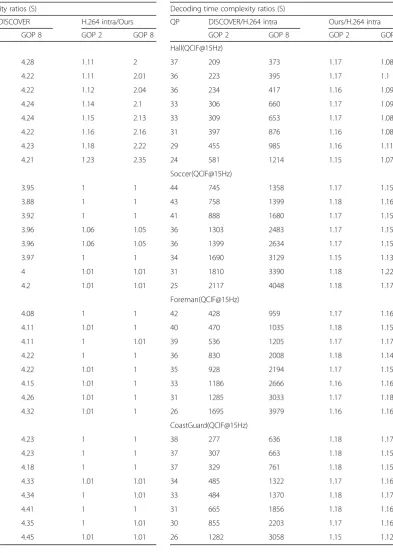
In the decoding, the proposed computational com-plexity is much lower (better) than that of DISCOVER, which uses a high complexity error correction decoding. As a result, the decoding time is one hundred to even three thousand times that of the H.264/AVC video de-coding. The high-complexity error correction decoding accounts for over 90% of decoding time. Therefore, the DISCOVER codec causes difficulties in real time system design as there is a high level of complexity at the de-coder. The proposed scheme performs well in this case, as its complexity increases by only 7~18% with the
H.264/AVC video decoding. This is the main reason for using the proposed PBMA instead of the traditional DVC for error correction decoding. As such, the pro-posed application can enable a more efficient real-time processing environment, as shown in Table 2.
5.3 Computational occupation time
Next, the functional block computational complexity time consumption needed further analysis and was cal-culated in percentage. The encoder distinguished three parts from Fig. 6, the first is the functional block Table 1The encoder time ratio of the proposed PB-based LVC
and DISCOVER codecs
Encoding time complexity ratios (S)
QP H.264 intra/DISCOVER H.264 intra/Ours
GOP 2 GOP 8 GOP 2 GOP 8
Hall(QCIF@15Hz)
37 1.7 4.28 1.11 2
36 1.7 4.22 1.11 2.01
36 1.7 4.22 1.12 2.04
33 1.71 4.24 1.14 2.1
33 1.71 4.24 1.15 2.13
31 1.71 4.22 1.16 2.16
29 1.71 4.23 1.18 2.22
24 1.73 4.21 1.23 2.35
Soccer(QCIF@15Hz)
44 1.66 3.95 1 1
43 1.67 3.88 1 1
41 1.66 3.92 1 1
36 1.68 3.96 1.06 1.05
36 1.68 3.96 1.06 1.05
34 1.69 3.97 1 1
31 1.69 4 1.01 1.01
25 1.73 4.2 1.01 1.01
Foreman(QCIF@15Hz)
42 1.68 4.08 1 1
40 1.69 4.11 1.01 1
39 1.69 4.11 1 1.01
36 1.71 4.22 1 1
35 1.71 4.22 1.01 1
33 1.71 4.15 1.01 1
31 1.73 4.26 1.01 1
26 1.75 4.32 1.01 1
CoastGuard(QCIF@15Hz)
38 1.7 4.23 1 1
37 1.71 4.23 1 1
37 1.71 4.18 1 1
34 1.72 4.33 1.01 1.01
33 1.74 4.34 1 1.01
31 1.75 4.41 1 1
30 1.74 4.35 1 1.01
26 1.76 4.45 1.01 1.01
Table 2The decoder time ratio of the proposed PB-based LVC and DISCOVER codecs
Decoding time complexity ratios (S)
QP DISCOVER/H.264 intra Ours/H.264 intra
GOP 2 GOP 8 GOP 2 GOP 8
Hall(QCIF@15Hz)
37 209 373 1.17 1.08
36 223 395 1.17 1.1
36 234 417 1.16 1.09
33 306 660 1.17 1.09
33 309 653 1.17 1.08
31 397 876 1.16 1.08
29 455 985 1.16 1.11
24 581 1214 1.15 1.07
Soccer(QCIF@15Hz)
44 745 1358 1.17 1.15
43 758 1399 1.18 1.16
41 888 1680 1.17 1.15
36 1303 2483 1.17 1.15
36 1399 2634 1.17 1.15
34 1690 3129 1.15 1.13
31 1810 3390 1.18 1.22
25 2117 4048 1.18 1.17
Foreman(QCIF@15Hz)
42 428 959 1.17 1.16
40 470 1035 1.18 1.15
39 536 1205 1.17 1.17
36 830 2008 1.18 1.14
35 928 2194 1.17 1.15
33 1186 2666 1.16 1.16
31 1285 3033 1.17 1.18
26 1695 3979 1.16 1.16
CoastGuard(QCIF@15Hz)
38 277 636 1.18 1.17
37 307 663 1.18 1.15
37 329 761 1.18 1.15
34 485 1322 1.17 1.16
33 484 1370 1.18 1.17
31 665 1856 1.18 1.16
30 855 2203 1.17 1.16
classifier and skip block mask, the second is the func-tional block rearrangement and sub-framing, and the third is the H.264/AVC intra frame encoding and simi-larly for comparison in GOP 2 and 8. Overall, because the DVC design aim is low-complexity encoding, the highest computational complexity occurs with the
H.264/AVC intra encoding, and execution time accounts for more than 99.5%. Although the proposed scheme adopts partial inter frame encoding, it exhibits higher complexity than the traditional DVC intra frame encod-ing. However, it is observed that the increasing partial inter frame coding time is lower than 0.5%, from Table 3,
Table 3The encoder time percentage of the proposed PB-based LVC
Percentage of the encoding time
GOP 2 GOP 8
QP Classifier and skip block mask
Rearrangement and sub-framing
H.264/AVC intra Classifier and skip block mask
Rearrangement and sub-framing
H.264/AVC intra
Hall (%, QCIF@15Hz)
37 0.36 99.64 0.55 0.22 99.08
36 0.36 99.64 0.55 0.22 99.09
36 0.35 99.65 0.54 0.22 99.09
33 0.34 99.66 0.53 0.21 99.12
33 0.33 99.67 0.53 0.21 99.12
31 0.33 99.67 0.52 0.21 99.14
29 0.32 99.68 0.51 0.2 99.16
24 0.29 99.71 0.47 0.19 99.21
Soccer (%, QCIF@15Hz)
44 0.39 99.61 0.46 99.54
43 0.39 99.61 0.46 99.54
41 0.38 99.62 0.45 99.55
36 0.36 99.64 0.42 99.58
36 0.36 99.64 0.42 99.58
34 0.34 99.66 0.4 99.6
31 0.31 99.69 0.36 99.64
25 0.26 99.74 0.3 99.7
Foreman (%, QCIF@15Hz)
42 0.34 99.66 0.43 99.57
40 0.33 99.67 0.41 99.59
39 0.32 99.68 0.41 9959
36 0.3 99.7 0.38 99.62
35 0.29 99.71 0.37 99.63
33 0.28 99.72 0.35 99.65
31 0.26 99.74 0.33 99.67
26 0.22 99.78 0.27 99.73
Coast Guard (%, QCIF@15Hz)
38 0.37 99.63 0.42 99.58
37 0.36 99.64 0.41 99.59
37 0.36 99.64 0.41 99.59
34 0.33 99.67 0.38 99.62
33 0.32 99.68 0.36 99.64
31 0.31 99.69 0.35 99.65
30 0.28 99.72 0.32 99.68
and below one in 200. Therefore, the time proportion is extremely low.
Hall monitor in GOP 8, however, is a low motion video sequence, and most blocks are skipped; thus, functional block sub-framing is used. The encoder is therefore partially occupied with the sub-framing block during processing time.
In addition, the decoding time occupation analysis is divided into four parts from Fig. 7. First is functional block H.264/AVC intra frame decoding, second is func-tional block sub-frame recovery and inverse rearrange-ment, third is functional block block padding, and the final is functional block pixel padding. Overall, the
Table 4The decoder time percentage of the proposed PB-based LVC
Percentage of the decoding time
GOP 2 GOP 8
QP H.264/AVC
intra
Sub-frame recovery and inverse rearrange
Block padding
Pixel padding
H.264/AVC intra
Sub-frame recovery and inverse rearrange
Block padding
Pixel padding
Hall (%, QCIF@15Hz)
37 84.3 9.42 6.28 96.34 0.73 1.83 1.1
36 84.3 9.42 6.28 96.3 0.74 1.85 1.11
36 84.31 9.41 6.27 96.3 0.74 1.85 1.11
33 84.5 9.3 6.2 96.39 0.72 1.81 1.08
33 84.26 9.44 6.3 96.36 0.73 1.82 1.09
31 84.34 9.4 6.27 96.27 0.75 1.86 1.12
29 84.32 9.41 6.27 96.4 0.72 1.8 1.08
24 84.38 9.37 6.25 96.4 0.72 1.8 1.08
Soccer (%, QCIF@15Hz)
44 84.51 9.3 6.2 86.02 8.39 5.59
43 84.55 9.27 6.18 85.41 8.76 5.84
41 84.37 9.38 6.25 85.82 8.51 5.67
36 84.72 9.17 6.11 85.61 8.63 5.76
36 84.72 9.17 6.11 85.61 8.63 5.76
34 84.59 9.24 6.16 85.82 8.51 5.67
31 84.73 9.16 6.11 86.46 8.12 5.42
25 84.88 9.07 6.05 85.96 8.42 5.62
Foreman (%, QCIF@15Hz)
42 84.73 9.16 6.11 85.89 8.47 5.64
40 84.88 9.07 6.05 85.84 8.5 5.66
39 84.75 9.15 6.1 85.78 8.53 5.69
36 84.65 9.21 6.14 85.77 8.54 5.69
35 84.7 9.18 6.12 86.09 8.35 5.56
33 84.81 9.11 6.08 86.06 8.36 5.58
31 84.87 9.08 6.05 86.31 8.22 5.48
26 84.98 9.01 6.01 86.2 8.28 5.52
Coast Guard (%, QCIF@15Hz)
38 84.6 9.24 6.16 85.71 8.57 5.71
37 84.37 9.38 6.25 85.72 8.57 5.71
37 84.37 9.38 6.25 85.72 8.57 5.71
34 84.37 9.38 6.25 85.6 8.64 5.76
33 84.51 9.29 6.2 85.79 8.53 5.68
31 84.63 9.22 6.15 85.75 8.55 5.7
30 84.72 9.17 6.11 85.85 8.49 5.66
decoder exhibits the same performance as the encoder, in that the greatest complexity occurs with H.264/AVC intra decoding, accounting for about 85%, while the sec-ond highest execution time occurs with functional block padding and occupies about 8~9%, from Table 4. The decoder’s improvement performance relies on this func-tion, and the two important algorithms, PBMA and mode decision at decoder, also perform in this part.
6 Conclusions
In this paper, a PB-based LVC architecture was pro-posed, which compensates for the current
high-complexity decoder and lower performance DVC
schemes. Following the experiment results, it is clear that the proposed architecture is able to greatly reduce the decoder complexity by a hundred-fold in addition to other marginal performance improvements. Moreover, the PBMA and four flexible block type mode decision scheme is able to effectively transfer the motion estima-tion and the mode decision algorithms to the decoder. Its performance can approach that of H.264/AVC video coding, and is better than traditional DVC solutions.
Funding
This work has been funded by grants 5132-28Y, from the Education Ministry of Taiwan R.O.C Government.
Authors’contributions
TL and FsT conceived and designed the research. TL performed the experiments and analyzed the data. TL and FsT wrote and edited the manuscript. Both authors read and approved the final manuscript.
Competing interests
The authors declare that they have no competing interests.
7 Publisher’s Note
Springer Nature remains neutral with regard to jurisdictional claims in published maps and institutional affiliations.
Author details
1
The Electrical Engineering Department of National Sun Yat-sen University, 70 Lienhai Rd., Kaohsiung 80424, Taiwan, Republic of China.2The Institute of Communication Engineering of National Sun Yat-sen University, 70 Lienhai Rd, Kaohsiung 80424, Taiwan, Republic of China.
Received: 10 May 2015 Accepted: 18 April 2017
References
1. J Slepian, J Wolf, Noiseless coding of correlated information sources. IEEE Trans. Inf. Theory.19(4), 471–480 (1973)
2. A Wyner, J Ziv, The rate-distortion function for source coding with side information at the decoder. IEEE Trans. Inf. Theory.22(1), 1–10 (1976) 3. B Girod, A Aaron, S Rane, D Rebollo-Monedero, Distributed video coding.
Proc. IEEE.93(1), 71–83 (2005)
4. X Artigas, J Ascenso, M Dalai, S Klomp, D Kubasov, M Ouaret,The DISCOVER Codec: Architecture, Techniques and Evaluation. (Picture Coding Symposium, Lisbon, 2007)
5. C Brites, J Ascenso, J Pedro, F Pereira, Evaluating a feedback channel based transform domain Wyner-Ziv video codec. Signal Process. Image Commun. 23, 269–297 (2008)
6. R Puri, A Majumdar, K Ramchandran, PRISM: a video coding paradigm with motion estimation at the decoder. IEEE Trans. Image Process.16(10), 2436– 2448 (2007)
7. CC Chiu, SY Chien, CH Lee, VS Somayazulu, YK Chen, Hybrid distributed video coding with frame level coding mode selection. 19th IEEE International Conference on Image Processing, 1561–1564 (2012) 8. CC Chiu, HF Wu, SY Chien, CH Lee, VS Somayazulu, YK Chen, Hardware
Architecture Design of Hybrid Distributed Video Coding with Frame Level Coding Mode Selection. Asia-Pacific Signal & Information Processing Association Annual Summit and Conference, 1–4 (2012)
9. J Ascenso, C Brites, F Pereira,Improving frame interpolation with spatial motion smoothing for pixel domain distributed video coding. 5th EURASIP Conference on Speech and Image Processing, Multimedia Communications and Services. (Slovak Republic, Smolenice, 2005), 1–6
10. T Clercks, A Munteanu, J Cornelis, P Schelkens, Distributed Video Coding with Shared Encoder/Decoder Complexity. IEEE International Conference on Image Processing, San Antonio, TX. 6, VI-417–VI-420 (2007)
11. H Chen, E Steinbach,Flexible Distribution of Computational Complexity Between the Encoder and the Decoder in Distributed Video Coding. (IEEE Int. Conf. Multimedia and Expo, Hannover, Germany, 2008),pp. 801–804 12. F Dufaux, T Ebrahimi, Encoder and Decoder Side Global and Local Motion
Estimation for Distributed Video Coding. 2010 IEEE International Workshop on Multimedia Signal Processing, 339–344 (2010)
13. A Abou-Elailah, F Dufaux, J Farah, M Cagnazzo and B Pesquet-Popescu, Fusion of Global and Local Motion Estimation for Distributed Video Coding, IEEE Trans. Circuits Syst. Video Technol. 23 (1) (2013) 14. DG Lowe, Distinctive image features from scale-invariant keypoints. Int. J.
Comput. Vision60(2), 91–110 (2004)
15. Y-J Wang, S-L Hsu, T-Y Cheng, C-H Lee, S-Y Chien, Feedback-Channel-Free Distributed Video Coding with Dynamic Skip-Mode Threshold. International Conference on Image Processing, (2012)
16. Y-J Wang, S-L Hsu, T-Y Cheng, C-H Lee, S-Y Chien, Low-Complexity Feedback-Channel-Free Distributed Video Coding with Enhanced Classifier. IEEE International Symposium on Circuits and Systems. (2013)
17. EG Iain, H Richardson, 264 and MPEG-4 Video Compression: Video Coding for Next-generation Multimedia. (John Wiley & Sons, 2003)
18. T Wiegand, GJ Sullivan, G Bjontegaard, A Luthra, Overview of the H.264/AVC video coding standard. IEEE Trans. Circuits Syst. Video Technol.13(7), 560– 576 (2003)
19. J Zhang, JF Arnold MR Frater, A cell-loss concealment technique for MPEG-2 coded video. IEEE Trans. Circuits Syst. Video Technol.10(4), 659–665 (2000) 20. AA Efros, TK Leung, Texture Synthesis by Nonparametric Sampling. IEEE Int.
Conf. Computer Vision., 1033–1038 (1999)
21. S Rane, G Sapiro, M Bertalmio, Structure and texture filling-in of missing image blocks in wireless transmission and compression applications. IEEE Trans. Image Process. 296–303 (2003)
Submit your manuscript to a
journal and benefi t from:
7Convenient online submission 7Rigorous peer review
7Immediate publication on acceptance 7Open access: articles freely available online 7High visibility within the fi eld
7Retaining the copyright to your article