RESEARCH ARTICLE
Development of friction free controller
for electro-hydrostatic actuator using feedback
modulator and disturbance observer
Sho Sakaino
*†and Toshiaki Tsuji
†Abstract
Hydraulic actuators have high power-to-weight ratios, making them suitable for high-power robotic applications such as in walking robots and construction machines. However, large frictional forces in hydraulic actuators, rotary hydrau-lic actuators in particular, degrade the control performance. To suppress frictional forces and increase robustness against modeling errors, this study considered the integration of feedback modulators (with minimum control inputs exceeding static frictional forces) with disturbance observers. In the proposed controller, nonlinear static frictional forces are suppressed by the feedback modulators and linear disturbances are suppressed by the disturbance observ-ers. The validity was experimentally verified in this study.
Keywords: Hydraulic system, Friction compensation, Electro-hydrostatic actuator, Disturbance observer, Feedback modulator
© The Author(s) 2017. This article is distributed under the terms of the Creative Commons Attribution 4.0 International License (http://creativecommons.org/licenses/by/4.0/), which permits unrestricted use, distribution, and reproduction in any medium, provided you give appropriate credit to the original author(s) and the source, provide a link to the Creative Commons license, and indicate if changes were made.
Background
Recent trends in robotics require actuators with high power-to-weight ratios. For example, robots designed to support human movement must be light for safety and to enable standing and walking, and machines used for con-struction must have sufficient force to manipulate large objects. Hydraulic actuators are commonly used in these applications because of their power-to-weight ratios and their remote driving units (i.e., power sources, electric motors, servo units, and oil tanks).
Two types of circuits are commonly used to control hydraulic actuators: open and closed. In open circuits, power generated by a motor is reduced and regulated by a valve and is transmitted to a hydraulic actuator. Much of the power is dissipated in the valve, resulting in lower efficiency and larger system designs. Figure 1 shows a schematic of an open hydraulic circuit. In closed cir-cuits (known as electro-hydrostatic actuators or EHAs) a servomotor generates and directly controls the power.
Figure 2 shows a schematic of a closed hydraulic circuit (EHA). Closed hydraulic circuits offer three advantages: (1) the systems are simple and small; (2) the efficiency is high; (3) valve-related nonlinearities are omitted. However, there is a drawback in EHAs; the control per-formance of EHAs is worse than that of open hydrau-lic circuits. Therefore, control performance of EHAs is improved in this study.
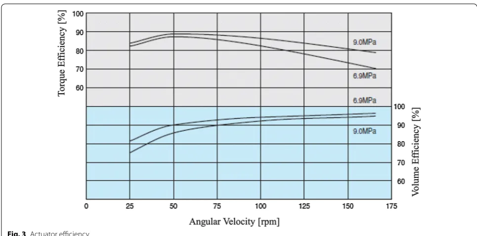
Given that many of the inherent nonlinearities are omitted in EHAs, the system dynamics can be well char-acterized by a linear model [1]. Hence, complicated con-trollers such as adaptive concon-trollers [2], sliding mode controllers [3], and fuzzy controllers [4] are not neces-sary, while those are often implemented in hydraulic systems. However, actuator efficiencies still introduce nonlinear effects. Figure 3 shows the volume and torque efficiencies for the S-380 actuator made by Eaton Indus-tries Ltd., and used in this study [5]. Note that actuator efficiencies are dependent on the angular velocity. Fur-thermore, efficiencies in the low speed domain are not given; high oil leakage in the low-speed domain poses a challenge in the accurate estimation of efficiencies. The effects of oil leakage are characterized as static friction because the applied force decreases in the low speed
Open Access
*Correspondence: [email protected]
Fig. 1 Open hydraulic circuit
Fig. 2 Closed hydraulic circuit (electro-hydrostatic actuator)
domain. Therefore, the suppression of the frictional effect is essential for fine control.
Prior research purports that the frictional effect can be suppressed using adaptive control [6, 7]; however, adaptive control requires significant tuning param-eters and is quite difficult to implement. For practical implementation, hydraulic controllers should be easy to design. Feedback modulators (FMs) have been suc-cessfully implemented in a hydraulic system to suppress static friction [8]. When an FM’s minimum force is set to exceed the maximum static frictional force, systems are then free from static friction. However, FMs cannot sup-press disturbances caused by gravity, viscosity, modeling errors, etc. Disturbance observers (DOBs) can instead be used to suppress these types of disturbances [9–11]. However, DOBs generate residual oscillation if the static friction is large. Yao et al. proposed an extended state observer to compensate for disturbances in hydraulic systems [12]. However, the controller was designed for open hydraulic circuits. To address these issues, we pro-posed a new controller that integrates FMs and DOBs [13]. In the previously proposed controller, FMs are only activated in the low-speed domain and DOB compen-sation value updates are concurrently suspended. The previously proposed controller offers three advantages: (1) in the low-speed domain, the FMs eliminate fric-tional effects; (2) in other speed domains, DOBs operate as normal; (3) the design is simple and does not require strict parameter tuning.
In the previous study [13], the proposed control-ler was implemented in an open hydraulic circuit. The proposed controller’s effectiveness for EHAs was unconfirmed because of the different dynamic char-acteristics of open and closed circuits. In EHAs, the
hydraulic pumps introduce additional static friction, resulting in greater frictional force. We implemented the proposed controller in an EHA and verified its effectiveness. To overcome the shortcomings in prior studies, we compared the proposed controller with other friction compensators, including dither signals. Dither signals have previously been shown to eliminate frictional effects [14].
Modeling
Hydraulic actuator and robot arm
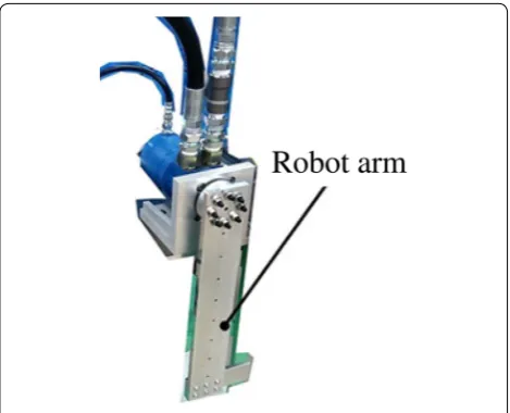
Figures 4 and 5 show the actual hydraulic actuator/ robot arm (Eaton Industries, Ltd., S-380) and a force model of the hydraulic actuator/robot arm used in this study, respectively. In this paper, the hydraulic actuator and robot arm are referred to as load-side. The angular response of the hydraulic actuator was obtained using an optical encoder with 17 bit resolution in every 1 ms. The dynamics of the load-side is given as follows:
where m, θ, D, p, are inertia, angle, displacement, and pressure difference between the input and output ports, respectively. ηtL is torque efficiency of the hydraulic
actuator. Response variables are denoted by the super-script res. Variables with a subscript L represent the load-side.
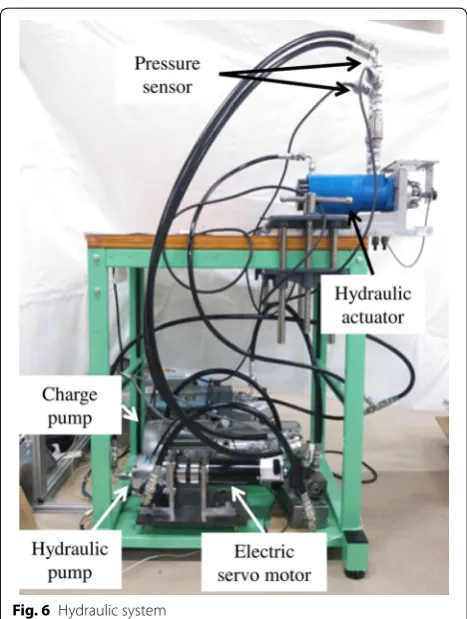
Hydraulic system
Figure 6 depicts the complete hydraulic system used in this study. An electric servomotor drives a hydraulic pump (Eaton Industries, Ltd., MA-03) that then supplies oil to the hydraulic actuator. In this paper, the hydraulic pump and the servomotor are referred to as motor-side. The equation of motion of the motor-side is given as follows:
where Kt and IMref are a servomotor’s torque constant and current reference, respectively. Variables with a subscript
M represent the motor-side. ηtM is the torque efficiency of the hydraulic pump.
By substituting (1) into (2), the following dynamic rela-tionship is obtained.
Since the oil flow is continuous, the following equation is satisfied.
(1) mLθ¨Lres= ηtL
DL 2πp
res
(2)
mMθ¨Mres= ηtMKtIMref − DM
2πp
res
(3) mMθ¨Mres= ηtMKtIMref −
1
ηtL DM
DL mLθ¨Lres
(4)
DM
2π
˙
θMres= DL 2π
˙
Finally, the dynamics can be calculated from (3) and (4):
where n is the hydraulic actuator/pump displacement ratio.
Note that ηtM and ηtL suddenly decrease at near-zero speeds, resulting in static friction.
Methods
This section describes the proposed controller. The torque reference for the proposed controller is given by a proportional-derivative (PD) controller as follows:
where τPDref is a torque reference calculated by the PD con-troller and Kp and Kv are the proportional and derivative
gains, respectively. There are many controllers that use proportional-integral-derivative controllers to improve the steady-state performance. Instead, of these control-lers, a DOB with the PD controller is implemented in this study because DOBs can powerfully suppress dis-turbances, eliminating the necessity of integral control [9, 10]. Note that parameter tuning of DOBs is quite easy because the performance of the DOB can be designed using a simple parameter, cut-off frequency of a low-pass filter.
To limit the residual oscillation generated by the integra-tors of DOBs under large frictional forces, the estimation of the disturbance torque is suspended in the low-speed domain. We propose a new DOB as follows:
(5)
(n2ηtLmM+mL)θ¨L= nηtMηtLKtIMref
n= DL
DM
(6) τPDref =mKp(θLcmd−θLres)+Kv(θ˙Lcmd− ˙θLres)
m= (n
2η
tLmM+mL)
nηtMηtL ,
where τref and τˆdis are a temporal torque reference and the
estimated disturbance torque by the DOB, respectively. The suffix [k] stands for a kth value in the discrete time series. The method for determining τˆdis is the same as in reference
[9]. Values of τˆmemdis reflect τˆdis values; updates are suspended
when the velocity falls within the low-speed domain
| ˙θL| ≤Th1. Friction force overcompensation is avoided using this approach. In addition, as long as disturbances are step, τˆmemdis [k+1] = ˆτdis[k+1] = ˆτdis[k] = ˆτmemdis [k] holds
at any time. Then, the memory hardly affects the tracking performance.
Ideally, Th1 is zero. However, because of computational errors of the angular velocity, the measured values may show a non-zero speed even if the actual motion stops. Therefore, Th1 should be the smallest value that is greater
than the computational errors.
Frictional force that cannot be fully compensated for generates steady-state errors. We quantize τref such that the minimum output torque is greater than the maxi-mum static friction. FMs—dynamic quantizers with a simple structure and a low pass filter—provide an easy and effective way to control the quantization errors. Note that system models are generally not required for FMs; this feature helps to ensure the robustness of the control-ler. Furthermore, some quantizers exhibit better perfor-mance with the explicit use of system dynamics in place of a system model [15, 16]; however, the difference in performance is negligible despite the complexity of the compensator.
Figure 7 shows a schematic of an FM. In this diagram,
Q(s) satisfies 1−Q(s)=Ts+Ts1
2
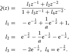
and S/H stands for “sample and hold,” which describes the temporal resolu-tion of the servomotor. τCref is an intermediate torque ref-erence and τQref is a quantized torque reference. Defining a time constant T as T =aSt, with a sampling period St and
a constant a>1, gives a pulse transfer function as follows:
Note that as a decreases, the quantization error also decreases. Using Q(s), τref, the quantized torque
(7)
τref[k] = τPDref[k] + ˆτmemdis [k]
(8)
ˆ
τmemdis [k+1] =
ˆ
τdis[k+1] | ˙θL|>Th1)
ˆ
τmemdis [k] | ˙θL| ≤Th1),
(9) Q(z)= l1z
−1+l2z−2
1+l3z−1+l4z−2.
l1= −e−a1 +
1
ae −1a +1,
l2= e−a2 −
1
ae
−1a −e−1a,
of the servomotor τQref, and the quantization error
ǫ=τCref −τQref, the following relationship can be derived:
In general, τQref can always be quantized. In this study, τref is quantized only in the low-speed domain to reduce the effect of quantization errors.
⌊ ⌋ is a floor function where d is a design parameter that should be greater than the maximum static frictional force. The second and third conditions reflect that τQref is free from static friction in the low-speed domain. Theo-retically, Th2 can be arbitrary values that are greater than the static friction since quantization errors can be com-pensated for by the FM. However, a large Th2 results in harmonic distortion sounds of servomotors. Therefore, for practical implementation, designers should roughly identify the minimum velocity that is not in the static fric-tion domain and choose a value of Th2 that is certainly
(10)
τQref =τref +(1−Q(s))ǫ.
(11)
τQref =
τCref | ˙θL| > Th2) �
τCref
d +1 �
d (0≤ ˙θL≤Th2)
�
τCref
d −1 �
d (−Th2≤ ˙θL < 0)
greater than the identified value. Before torque efficien-cies are reduced, τCref should be quantized. The condition
Th1<Th2 suppresses frictional effects.
Lastly, the current reference IMref is obtained as follows:
Figure 8 shows a comprehensive flow diagram for the proposed controller, where gd is the DOB cutoff
fre-quency. “FM” stands for the block diagram of the FM as shown in Fig. 7.
Linear disturbances such as gravity are compensated for by the DOB while nonlinear static friction is compen-sated for by the FM. To avoid overcompensation of the integrator in the DOB, the update of the compensation value is suspended at low speeds. Then, designers can treat EHAs as if they are simple second-order systems without any disturbances resulting in an easy-to-tune controller.
High-frequency switching may harm the servomo-tor and hydraulic pump; a large T should be selected to prevent damage. As a trade-off, control performance is degraded. If the control bandwidth is far broader than that of other controllers, FMs guarantee stability for closed-loop systems [17]. This assumption can usually be assured. For example, the FM bandwidth in this study was more than 100 times broader than that of other con-trollers, the PD controller and the DOB. In the experi-ment, the bandwidths of the PD controller and the DOB were set to 10 and 20 rad/s, respectively, while the band-width of the FM was 5980 rad/s.
Results and discussion
The effectiveness of the proposed controller was experi-mentally verified in this study. Table 1 shows the param-eters used in this experiment. Before the primary experiment was conducted, the static friction of the EHA was initially measured.
The input torque was gradually increased, and we checked the value when the robot started moving. We
(12) IMref = τ
ref Q Kt
.
Fig. 6 Hydraulic system
found that the static friction did not exceed 70 Nm; d was set to 70 Nm.
Performance comparison
In this experiment, step and sinusoidal commands were given to the proposed controller and two conven-tional controllers. The two convenconven-tional controllers included a PD controller and the following: (1) a DOB with a control input given by IMref = K1
t(τ
ref PD + ˆτdis ) and (2) a DOB and a dither signal with a control input given by IMref = K1
t(τ
ref
PD + ˆτdis+τdither). The dither
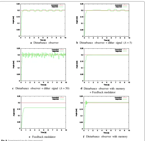
sig-nal, τdither=Asin(10πt), is intended to suppress static friction. Note that the frequency of the dither signal was determined according to reference [14]. Figures 9
and 10 show the experimental results with step and sinu-soidal (of 0.5 Hz) commands, respectively. Figures 9a and 10a show the results for the PD controller with the DOB. Figures 9b, c and 10b, c show the results for the PD
controller with the DOB and dither signal, with dither signal amplitudes of 5.0 and 50.0. The amplitudes were determined so that one of them was lower than the static friction and the other was greater than the static fric-tion. Since one with a greater value still had a value that was lower than the quantization value of the proposed method (70 Nm), the validity of the proposed method can be confirmed with respect to the two dither signals. Figures 9d and 10d show the results for the proposed controller. Figure 9e shows the result for the PD control-ler with the FM when the DOB was not used. Figure 9f shows the result for the PD controller with the proposed DOB given in (7) when the FM was not used. The red lines indicate the commands; the green lines show the responses.
As shown in Fig. 9a, residual oscillation was generated for the PD controller with the DOB, indicating difficulty when using integrators under a large static frictional force. Figure 9b shows that small-amplitude dither signals have almost no compensatory effect on the static friction. Figure 9c shows that large-amplitude dither signals lead to oscillatory responses. Without an accurate estimation of static friction, good control performance cannot be obtained by feedforward controllers. In Fig. 9e, because there was no integrator in the controller, residual oscil-lation was not generated while large steady-state errors were found due to the lack of a DOB. In Fig. 9f, there was no residual oscillation since the disturbance estimation was suspended at low speeds. However, small steady-state errors caused by static friction were found. Compar-atively, residual oscillation was almost fully suppressed in the proposed controller, while steady-state errors were almost suppressed, as shown in Fig. 9d. Even though the quantization value, d, was not strictly designed to exceed the static friction, the frictional effects were negligible when the actual value was approximately 24 Nm.
Table 1 Parameters
m Equivalent inertia 3.3 kgm2
Kp Proportional gain 100/s2
Kv Derivative gain 20/s
Kt Torque constant 0.147 Nm/A
gd Cut-off frequency of DOB 20 rad/s
St Sampling period 0.001 s
a Time constant ratio 1.05
D1 Displacement of pump 3.08 cm3/rev
D2 Displacement of motor 371 cm3
/rev
d Quantization 70 Nm
Th1 Threshold 0.00223 rad/s
Th2 Threshold 0.1 rad/s
ηtM Nominal torque efficiency 1
ηtL Nominal torque efficiency 1
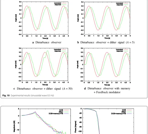
Differences among controller design were less appar-ent when considering the sinusoidal wave responses in Fig. 10a, b and d. The three controllers had almost the same performance in tracking sinusoidal waves because the effect of the static friction was not large for sinusoidal movement. In addition, owing to the overcompensation
of friction, Fig. 10c shows larger tracking errors. Fig-ure 11 shows the frequency characteristics of the three controllers: the PD controller with the DOB, the PD con-troller with the DOB and the dither signal (A=5), and the proposed method. As we can see from the figures, the characteristics were quite similar.
a b
c d
e f
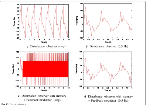
Figure 12 shows the control inputs, with a and b repre-senting inputs for the PD controller and the DOB and c and d representing inputs for the proposed controller. As shown in Fig. 12a, the input for the PD controller and the DOB was iteratively integrated to reach a maximum static friction of approximately 24 Nm. When the input exceeded the maximum static friction, an overshoot response was
initiated, and the input was again integrated to reach the maximum static friction. As shown in Fig. 12b, no static friction effects were observed for the same conventional controller in sinusoidal movements. As shown in Fig. 12c and d, the proposed controller effectively quantized inputs and static friction effects were suppressed. Furthermore, as shown in Fig. 12d, the proposed controller’s input was
a b
c d
Fig. 10 Experimental results (sinusoidal wave 0.5 Hz)
a b
similar to the conventional controller’s waveform input when the actuator did not experience static friction. Therefore, we can summarize that the proposed control-ler exhibited better performance at low speeds and com-parable performance at higher speeds when compared to conventional controllers. In other words, the proposed controller can improve the performance at low speeds without degrading the performance at high speeds.
Conclusions
Electro-hydrostatic actuators offer faster control speeds but suffer from higher static friction levels when com-pared with open hydraulic circuits. Therefore, EHAs require adequate controllers to compensate for the effects of static friction. In this study, FMs and DOBs were inte-grated to suppress the effects of static friction in EHAs. FMs guarantee precise and stable input quantization. As long as the input frequencies are far greater than the natural frequencies of the systems, quantization has lit-tle effect on the output. In this study, steady-state errors caused by linear disturbances were suppressed by the
DOB and the residual oscillation caused by static friction was suppressed by the FM. The integration was achieved using only two intuitive tuning parameters, Th1 and Th2 ; strict parameter tuning was not required. Furthermore, system models are not required for FM implementations, simplifying efforts in enhancing robustness. Hydraulic actuators have been associated with significant nonlin-earities that challenge controller design. In this study, we proved that the nonlinearities do not have to be prob-lematic. Using the proposed design, others can develop simple and easy-to-tune linear controllers for hydraulic actuator implementation, subsequently increasing the use and utility of hydraulic actuators.
We succeeded in improving the low speed performance while performance in high frequency domain has not been improved. The control bandwidth was still less than 1 Hz. We recently revealed that with sufficient friction compensation, EHAs actually have the characteristics of a two-mass resonant system. Then, the next target will be performance improvement in the high-speed domain by suppressing the resonance using FMs and DOBs.
a b
c d
Authors’ contributions
SS drafted the manuscript, participated in the design of the study, and carried out part of the studies. TT participated in its design and coordination. Both authors read and approved the final manuscript.
Acknowledgements
This study was supported in part by a Grant-in-Aid for Scientific Research (C) (16K06410).
Competing interests
The authors declare that they have no competing interests.
Received: 22 September 2016 Accepted: 6 December 2016
References
1. Kaminaga H, Ono J, Nakashima Y, Nakamura Y (2009) Development of backdrivable hydraulic joint mechanism for knee joint of humanoid robots. In: Proceedings of the 2009 IEEE international conference on robotics and automation, pp 1577–1582
2. Mohanty A, Yao B (2011) Integrated direct/indirect adaptive robust control of hydraulic manipulators with valve deadband. IEEE/ASME Trans Mechatron 16(4):707–715
3. Dasmahapatra S, Sarkar BK, Saha R, Chatterjee A, Mookherjee S, Sanyal D (2015) Design of an adaptive fuzzy-bias smc and validation for a rugged electrohydraulic system. IEEE/ASME Trans Mechatron 20(6):2708–2715 4. Ho TH, Ahn KK (2012) Speed control of a hydraulic pressure coupling
drive using an adaptive fuzzy sliding-mode control. IEEE/ASME Trans Mechatron 17(5):976–986
5. Eaton Industries Ltd. http://www.eaton.jp/EatonComJapan/. Accessed 25 Dec 2015
6. Guan C, Pan S (2008) Nonlinear adaptive robust control of single-rod electro-hydraulic actuator with unknown nonlinear parameters. IEEE Trans Control Syst Technol 16(3):434–445
7. Yao J, Deng W, Jiao Z (2015) Adaptive control of hydraulic actuators with lugre model based friction compensation. IEEE Trans Ind Electron 62(10):6469–6477
8. Ohgi T, Yokokohji Y (2008) Control of hydraulic actuator systems using feedback modulator. J Robot Mechatron 20(5):695–708
9. Ohnishi K, Shibata M, Murakami T (1996) Motion control for advanced mechatronics. IEEE/ASME Trans Mechatron 1(1):56–67
10. Lee IY, Kim TH, Choi SR (2008) Hydraulic servo system using a feedback linearization controller and disturbance observer—sensitivity of system parameters. In: the 7th JFPS international symposium on fluid power, pp 307–312
11. Won D, Kim W, Shin D, Chung CC (2015) High-gain disturbance observer-based backstepping control with output tracking error constraint for electro-hydraulic systems. IEEE Trans Control Syst Technol 23(2):787–795 12. Yao J, Jiao Z, Ma D (2014) Extended-state-observer-based output
feed-back nonlinear robust control of hydraulic systems with feed-backstepping. IEEE Trans Ind Electron 61(11):6285–6293
13. Sakaino S, Tsuji T (2014) Integration of disturbance observer and feed-back modulator for dead zone compensation of hydraulic actuator. In: Proceedings of the IEEE 40th annual conference of the IEEE industrial electronics society, pp 2786–2791
14. Phuong TT, Ohishi K, Mitsantisuk C (2014) Fpga-based high-performance force control system with friction-free and noise-free force observation. IEEE Trans Ind Electron 61(2):994–1008
15. Azuma S, Sugie T (2008) Synthesis of optimal dynamic quantizers for discrete-valued input control. IEEE Trans Autom Control 53(9):2064–2075 16. Minami Y, Azuma S, Sugie T (2009) Multirate-sampling dynamic
quantiz-ers for non-minimum phase linear control systems. SICE J Control Meas Syst Integr 2(4):229–235