RESEARCH ARTICLE
Optimization of the flexural rigidity of a
concentric pipe used in transmitting rotation
for arc-shaped forceps
Satsuya Noda
1*†, Toshio Takayama
2†and Toru Omata
2†Abstract
Arc-shaped forceps are important in pharyngeal cancer surgery, endoscopic sinus surgery, and single port surgery. Rotating the gripper of an arc-shaped forceps with respect to its shaft axis can improve the manipulability of the forceps. Concentric pipe structures consisting of inner and outer pipes are often used for this purpose. The inner pipe transmits rotations from its proximal end to distal end. However, the shape of the bent inner pipe is generally differ-ent from that of the outer pipe, and this causes large friction between the outer and inner pipes. To reduce friction, a plastic tube is often used for the inner pipe. However, since its torsional rigidity is low, this results in a large twist angle. This paper proposes a procedure to fit a metal bent inner pipe to an outer pipe by adjusting the flexural rigidity of the inner pipe with slits to reduce the friction. The procedure minimizes the twist angle between the proximal and distal end of the arc-shaped forceps by reducing the torque required to rotate its metal inner pipe. We develop a 5 mm for-ceps with a 3.5 mm inner pipe. The twist angle is 2.8° when a load torque of 20 Nmm is applied, which is a typical load torque for suturing, whereas the twist angle of a PEEK (polyetheretherketone) inner pipe is 24.3° in simulation. Ex vivo experiments show that the required forceps torque is small in simulated clinical scenarios.
Keywords: Concentric pipe, Arc-shaped forceps, Single port surgery, Pharyngeal cancer surgery, Flexural rigidity, Slit
© The Author(s) 2017. This article is distributed under the terms of the Creative Commons Attribution 4.0 International License (http://creativecommons.org/licenses/by/4.0/), which permits unrestricted use, distribution, and reproduction in any medium, provided you give appropriate credit to the original author(s) and the source, provide a link to the Creative Commons license, and indicate if changes were made.
Background
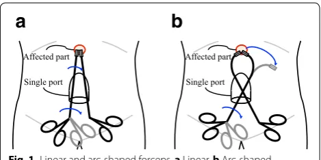
Arc-shaped forceps are important in pharyngeal cancer surgery, endoscopic sinus surgery [1], and single port sur-gery [2]. The use of a linear-shaped forceps in pharyngeal cancer surgery requires a patient to bend his or her neck backwards and increases the burden on the patient when compared with the surgery performed by an arc-shaped forceps. In single port surgery, the direction of the grip-per attached at the end of a linear-shaped forceps is lim-ited to that of the trocar as shown in Fig. 1a. The use of arc-shaped forceps can accommodate the direction of the gripper.
The manipulability of a forceps can be improved if its gripper can rotate about its shaft axis [3]. With respect to a linear-shaped forceps, the rotation of the proximal end simply generates the rotation of the distal end as shown in Fig. 1a. However, in an arc-shaped forceps, the rota-tion of the proximal end moves the posirota-tion of the distal end as shown in Fig. 1b. There are two types of structures to rotate the distal end, namely multi-joint and concen-tric pipe structures. Although the multi-joint structure enables the smooth rotation of the end of a forceps, it is complex and consists of several parts.
Surgical robots [4, 5] and employ a concentric pipe structure consisting of inner and outer pipes. The arc-shaped cannula of the da-Vinci surgical system [6–8] and TANKO (Adachi Industry) [9] also employ a concentric structure for the rotation of the distal end for single port surgery. This method enables a stiffer structure when compared with that in a multi-joint structure.
Generally, the shape of the bent inner pipe is different from that of the outer pipe as shown in Fig. 2. This causes
Open Access
*Correspondence: [email protected]
†Satsuya Noda, Toshio Takayama and Toru Omata contributed equally to
this work
1 Department of Mechano-Micro Engineering, Tokyo Institute
of Technology, 4259, Nagatsuta-cho, Midori-ku, Yokohama, Kanagawa 226-8502, Japan
contact between the outer and inner pipes, resulting in friction. A load torque as well as the friction increases the torque to rotate the inner pipe. A typical load torque for suturing is 20 Nmm [10]. Using a low friction plastic tube (e.g. PEEK/PTFE composite) for the inner pipe would be valid to reduce friction. However, the Young’s modulus of plastic is much lower than that of metal and the torsional rigidity is also low, which results in a large twist angle.
This study proposes a procedure to fit the bent metal inner pipe with respect to the outer pipe such that only the two ends of the pipes are in contact with each other by adjusting the flexural rigidity of the inner pipe with slits as shown in Fig. 2b. Thus, the friction between the pipes can be reduced even if the inner pipe touches the outer pipe in areas other than the ends of the pipes. An inner pipe with optimally adjusted slit intervals can mini-mize the twist angle.
Adjustment of the flexural rigidity with slits
Lower flexural rigidity is necessary for an inner pipe. However, torsional rigidity decreases and the twist angle increases as flexural rigidity decreases. Hence, this study proposes an optimization procedure to minimize the twist angle. The ease of manufacturing is also important to develop a practical medical tool, and it is also required
to adjust the flexural rigidity within the accuracy of machine tools. In this study, the flexural rigidity of an inner pipe with slits is adjusted.
Equivalent moment of inertia of area
In a pipe with slits, the moment of inertia of area (an index of flexural rigidity) cannot be calculated from a cross section of the pipes because it varies with respect to the region where the pipe is cut. Therefore, the equivalent moment of inertia of area I and the equivalent modulus of section Z [11] is defined by considering the bending of a pipe with slits with respect to that of a pipe without slits. I and Z can, respectively, be calculated by the fol-lowing expressions:
where F denotes the force acting on the end, E denotes the Young’s modulus of the material of the pipe, δ denotes
the deflection, σmax denotes the maximum tensile stress,
and L denotes the length of the cantilever. The finite ele-ment method (FEM) is used to analyze δ and σmax. The
minimum L is defined as one interval of the slits, but I is calculated using L=300 mm to increase accuracy.
Similarly, the equivalent polar moment of inertia of area Ip and the equivalent polar modulus of section Zp
are given by the following equations:
(1)
I = FL 3
3Eδ
(2)
Z = FL
σmax ,
(3)
Ip=
TL Gθ
(4)
Zp= T
τmax ,
a
b
Fig. 1 Linear and arc-shaped forceps. a Linear. b Arc-shaped
a
b
where T represents the torsional torque, G represents the shear modulus, θ represents the torsional angle, τmax
rep-resents the maximum shearing stress, and L represents the length of the cantilever. The calculations are also per-formed for L=300 mm.
Slit pattern
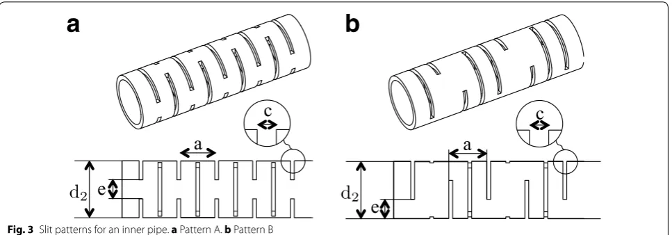
Various slit patterns exist in shaft couplings and in flex-ible forceps [12]. In order to enable the ease of manufac-turing, two patterns as shown in Fig. 3 are considered, and the pattern that provided low flexural rigidity and high torsional rigidity was selected. The inner pipe has slits in a direction vertical to the paper surface and has the same flexural rigidity in all radial directions. I and Ip
are calculated by using Mechanica (pro/Engineer). The shape parameters are as follow (see Fig. 3a, c, e):
Outer diameter: d2=6 mm
Inner diameter: d1=5 mm
Slit interval e=1.4 mm
Slit interval a=1.2, 1.6, 2.0, 2.4 and 3.0 mm
Slit interval c=0.3 and 0.4 mm.
Figure 4 shows the calculation results. The vertical axis is denoted by Ip, and the horizontal axis is denoted by I.
It is observed that Ip in Pattern A is higher than that in
Pattern B with the same I. Thus, Pattern A is selected in this study.
Boundary condition of the ends
Generally, arc-shaped forceps for pharyngeal cancer sur-gery or for single port sursur-gery have a curved portion in the distal end region, which is close to the affected part. In contrast, the forceps have a linear portion in the proxi-mal end region in which a handle is attached.
The bending formula is given by the following expression:
where κ denotes the curvature, and M denotes the
bend-ing moment. Additionally, M�=0 because κ�=0 at the
distal end as shown in Fig. 2b. Thus, two contact points are required to support the non-zero bending moment denoted by M. Conversely, κ =0 at the proximal end and
M=0. Therefore, a single contact point is sufficient. Procedure to optimally adjust the flexural rigidity
The outline of the procedure proposed in this study is as follows:
Step 1: Develop the database of I, Ip, Z, and Zp by var-ying the parameters for the slit.
Step 2: Set a target line, and calculate the curvature along the line.
(5) κ= −M
EI,
a
b
Fig. 3 Slit patterns for an inner pipe. a Pattern A. b Pattern B
Step 3: Calculate I, and determine the range of fH, which corresponds to the contact force act-ing on the proximal end. Define the range as
fmin≤fH ≤fmax.
Step 4: Determine fH that minimizes the twist angle of the inner pipe φ in the range
fmin≤fH ≤fmax. Calculate φ for each sam-pled fH as follows;
Step 4.1: Discretize the distribution of I.
Step 4.2: Confirm that the stress on the inner pipe is lower than the maximum permitted stress and that the error between the target and designed lines is less than the given allowable error. If the candidate does not meet these conditions, then it is discarded.
Step 5: Select fH that minimizes φ. If no candidates remain, then return to Step 2 and modify the target line. A solution is more likely to exist if the curvature of the forceps is reduced.
Each step can be described in detail as follows.
Step 1
The following values were selected for the slit parameters of the inner pipe. Their intervals are the smallest possible for usual machine tools.
a=1.2, 1.6, 2.0, 2.4, 3.0 mm e=1.0, 1.4, 1.8 mm c=0.3, 0.4, 0.5 mm
Calculate I for all combinations of the above cut parameters and sort the calculations in ascending order (I1<I2<· · ·<I45). This is defined as the database of I.
Similarly, Ip, Z and Zp are calculated corresponding to the
I database.
Step 2
This step provided a target line as shown in Fig. 5. Let L
be the total length of the target line, and let xt(s) and yt(s)
denote the position of the target line where s is the arc length from the distal end. The curvature κ(s) is given as
follows:
where ′′ denotes the second derivative with respect to s. Step 3
This step calculates I and determines the range of fH. The
relationship between the bending moment of the pipe
Mz(s) and fH is as follows:
where
(6) κ(s)=
x′′t(s)2
+
y′′t(s)2 ,
(7)
Mz(s)= −D(s)fH,
′ denotes the derivative with respect to s, and ⊗ is a scalar
operation for 2-D vectors defined as follows:
Let I(s) be the moment of inertia of area at s. The rela-tionship between I(s) and fH is given by
where
It is noted that I(s) cannot be lower than the minimum value in the database Imin. Therefore, fmin, which
corre-sponds to the minimum value of fH must satisfy the
fol-lowing expression:
Note 1: If the target line has linear segments, then
κ(s)=0 and I(s)→ ∞ from Eqs. (10) and (11). This type
of a target line is impractical and it must be modified. A pipe with no slit has the largest I(s), which is denoted by Imax. Hence, I(s) must be replaced by Imax in
por-tions where I(s)≥Imax. Since I(s) is reduced, fmin is also
reduced so that the proximal end of the pipe is as close as possible to that of the target line.
Then, fmax is set as the maximum value of fH. For
example, fmax=100fmin in simulation section. In
fmin≤fH ≤fmax, the fH that minimizes φ is determined.
Figure 6 shows the forces and moments acting on the inner pipe, which is in contact with the outer pipe only at its ends. The following symbols are defined:
Tm: axial torque acting on the inner pipe between the
proximal and distal ends
TOUT: output torque at the distal end of the inner pipe fz0: contact force in the z direction
(8) D(s)≡
xt(L)−xt(s)
yt(L)−yt(s)
⊗
−y′t(L)
xt′(L)
,
(9)
a b
⊗
c d
=ad−bc.
(10) I(s)=h(s)fH,
(11) h(s)= D(s)
Eκ(s).
(12)
fH ≥fmin= max
Imin h(s) =
C1 and C2: two contact points at the distal end
k: distance between C1 and C2
fy1 and −fy1: couple of forces acting at C1 and C2 in the
y direction
fz1 and −fz1: couple of forces acting at C1 and C2 in the
z direction
My moment about the Y-axis generated by fz1 and −fz1.
The equilibrium equation of the moment on the x-y plane is given as follows:
This results in the following expression:
where α, β, and γ are constants given by
Equation (14) can be obtained as follows. From Eq. (13), we have: (13) 0 0 =Tm
1 0
−Tm
xt′(L)
y′t(L)
+My
0 1
+fz0
yt(L)
−xt(L)
.
(14) Tm= TOUT+γ
α2(1−β2γ2)k2f2
H +β2TOUT2
1−β2γ2 ,
(15) α=D(0)
k
(16)
β=y′t(L)−xt(L)
yt(L)
1−x′t(L)
(17)
γ =µd2
k .
(18) fz0= −
1−xt′(L)
yt(L)
Tm
(19)
My=
y′t(L)−xt(L)
yt(L)
1−x′t(L)
Tm.
Since xt(L)≫k, it can be assumed that fy1 and −fy1
gen-erate Mz(0), Similarly, since yt(L)≫k, it is assumed that fz1 and −fz1 generate My. Hence,
Subtracting the friction acting at the distal end from Tm
results in TOUT. Hence,
where µ denotes the coefficient of friction. Eq. (14) can
be obtained by Eqs. (18–22).
The angle of torsion φ can be calculated by the
follow-ing expression:
where Ip(s) denotes the polar moment of inertia of area
at s.
fH is sampled in the range fmin≤fH ≤fmax to evaluate
the angle φ becuase the monotonicity of φ in Eq. (23)
can-not be determined as the value of fH increases.
Note 2: Ip of the denominator monotonically increases
as the value of I increases as shown in Fig. 4. From Eq. (10), I weakly increases as the value of fH increases. Thus, Ip weakly increases as the value of fH increases. Tm of the
numerator also monotonically increases as the value of
fH increases. Step 4
The following are calculated for each fHj =fmin+jh
where �h=(fmax−fmin)/N and j=0,. . .,N. Step 4.1
Discretize I (quantization) and s (sampling).
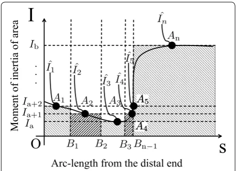
It is assumed that I(s) is given as shown in Fig. 7. I is dis-cretized by using the database of I as illustrated in Fig. 7.
1. In I1,. . .,I45 of the database, the set of Ii that satisfies minI(s)≤Ii≤maxI(s) is determined. It is assumed that Ia<Ia+1<· · ·<Ib are such Ii.
2. Let A1, A2,. . ., and An denote the intersection points between Ia<Ia+1<· · ·<Ib and I(s) in the ascending
order of s.
3. Let Iˆ1, Iˆ2, . . ., and Iˆn denote the values of I(s) at points
A1,A2,. . ., and An, respectively.
4. Bi be the middle point between Ai and Ai+1 on the s
axis, where i=1,. . .,n−1.
(20) fy1=
Mz(0) k =αfH
(21) fz1=
My
k = β kTm,
(22) TOUT=Tm−2
µd2 2
fy12 +fz12,
(23) φ=
L
0 Tm
GIp(s)
ds,
5. For each interval OB1, B1B2, . . ., and Bn−1An, I(s) can
be discretized as Iˆ1, Iˆ2, . . ., and Inˆ, respectively.
Note 3: The discretization of I(s) could cause an error between the proximal end positions of the designed and target lines. Therefore, fH is modified so that they are as
close as possible.
Step 4.2
The following three procedures are executed for confirmation:
Simple stress confirmation
Let σnet be the maximum stress when both the
bend-ing and torsional loads are applied. σnet must be smaller
than the proof stress σproof of the material (typically, 0.2%
proof stress). Accurate calculation of the stress by using FEM (CPU: Core i7 3.4 GHz) requires a large calculation time exceeding an hour. Therefore, the following pre-screening is performed using a simple criterion. Let σs
and τs denote the maximum bending and the maximum
torsional stresses, respectively.
where Z(s) and Zp(s) denote the modulus of section and
the polar modulus of section at s, respectively.
σnet should be calculated. However, the slits of the inner
pipe makes the calculation of σnet from σs and τs difficult.
In many cases of this study, σs≫τs. Moreover, the stress
concentration points of the bending load are different from those of the torsional load as will be described in
(24)
σs=Max Mz(s)
Z(s)
(25) τs=Max
Tm Zp(s),
the simulation section. Therefore, this step regards that
σnet≈σs and excludes the jth candidate fHj if σs> σproof.
Error
The maximum error between the target and the designed lines is denoted by ε. It is confirmed that the calculated
value is smaller than a given allowable error ε¯ . If ε <ε¯,
then the procedure moves to the next step. If ε >ε¯, then
the sampling intervals are randomly selected and modi-fied by several millimeters, and the procedure returns to Step 4.2 (1). It should be noted that this random search is practical because the number of the sampling intervals is expected to be less than 10. If ε >ε¯ after this procedure,
then fHj is excluded. Final stress confirmation
σnet is calculated by using FEM. The jth candidate is
excluded, if σnet> σproof.
Step 5
The final step involves selecting fHj that minimizes φ. φ of
each candidate is obtained by Eq. (23). If no candidates of fHj remain, then the procedure returns to Step 2 and
modifies the target line by reducing its curvature.
Simulation and experiment Simulation of 8 mm forceps
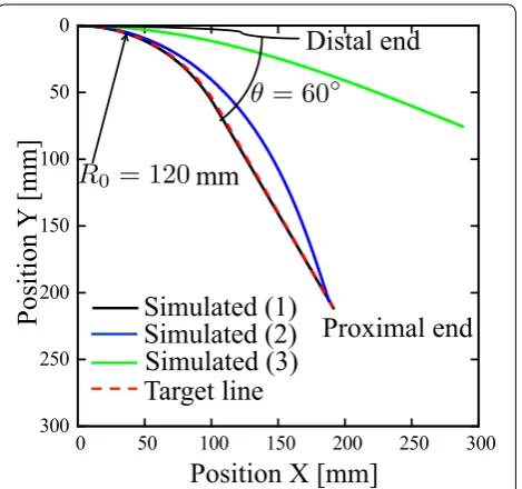
First, simulations for an arc-shaped forceps for single port surgery are performed. Its shape is given by the fol-lowing expression:
where R0 denotes the radius of the circular arc, and θ
denotes the central angle of the circular arc. Given the da-Vinci arc-shaped cannula [6], the parameters are set as R0=120 mm, θ =60° , and L=300 mm.
The material assumed in the FEM calculation is tita-nium (Ti-6Al-4V, Young’s modulus: 113 GPa, 0.2% proof stress: 828 MPa). The outer and inner diam-eters of the inner pipe are 6 and 5 mm, respec-tively. These dimensions were selected for an 8 mm forceps. From Eq. (12), the search range is obtained as
9.94×10⁻³≤fH ≤9.94×10⁻¹ N. However, because σnet> σproof when fH >1.5×10⁻¹ N, it is reduced to
9.94×10⁻³≤fH ≤1.5×10⁻¹ N. It is assumed that (26)
xt(s)
yt(s)
=R0
sinRs
0
1−cosRs
0
(0≤s≤R0θ )
(27)
xt(s) yt(s)
=R0
sinθ
1−cosθ
+(s−R0θ )
cosθ
sinθ
µ=0.3,k=10 mm and TOUT =20.0 Nmm. The value of
TOUT is determined by referring to the suture task in [10].
Table 1 shows the calculation result of φ for each
candidate. From Table 1, φ is observed as the smallest
when fH =0.13 N. Table 2 shows the slit parameters
and errors. Three different slits are cut in the intervals
OB1, B1B2, and B2B3. In Step 4.2 (1), σs=622 MPa and τs=132 MPa, and in Step 4.2 (3), σnet=678 MPa, which
is smaller than the 0.2% proof stress of 828 MPa.
Figure 8(1) shows the bent shape of the inner pipe. For purposes of comparison, Fig. 8(2) shows the line with slits cut uniformly, and (3) shows the line with no slits. In (3), fH is such that the maximum stress σs is equal to the
proof stress σproof. Line (1) is close to the target line (ε=
1.25 mm) whereas Lines (2) and (3) are not close to the target line (ε = 16.54, 161.9 mm). From Eq. (23), the twist
angle is φ=4.30° in (1).
Note 4: The twist angle can also be obtained from the FEM simulation. It is φ=4.18° and close to the twist
angle from Eq. (23)
Simulation of 5 mm forceps
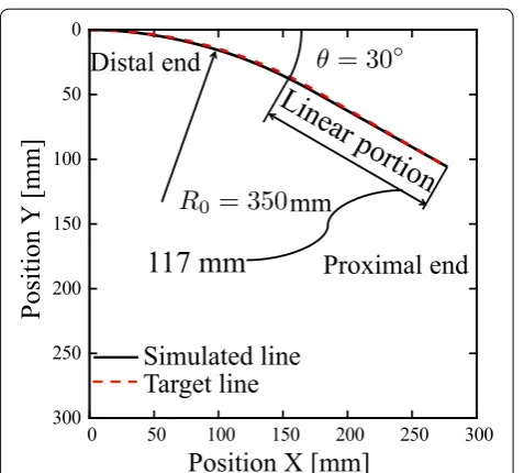
An arc-shaped forceps with diameter of 5 mm is simu-lated. Figure 9 shows the target line with the shape parameters R0=350 mm, θ =30° and L=300 mm.
This line is determined by referring to a forceps for phar-yngeal cancer surgery that is practically used and a for-ceps for single port surgery (for example, Type KTY1 of ADACHI-TANKO forceps [13]).
Strong surgical stainless (SUS630, Young’s modulus: 205 GPa, 0.2% proof stress : 1175 MPa) was selected as the material for this forceps. From Eq. (12), the search range is determined as 7.23×10⁻²≤fH ≤7.23 N. However,
because σ > σproof when fH >3.0×10⁻¹ N, the search
range is reduced to fHj in 7.23×10⁻²≤fH ≤3.0×10⁻¹
N. The other experimental parameters are the same as those discussed in Section Simulation of 8 mm forceps.
Table 3 shows the calculated results of φ. The value
of φ is the smallest for the 5th candidate, and it is 2.93°.
Table 4 shows the slit parameters and errors, and it is observed that two different slits are cut in the interval
OB1 and B1B2. Figure 9 shows the line of the inner pipe
obtained by simulation. The designed line is close to the target line (ε=1.45 mm).
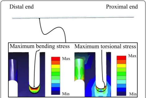
Table 5 lists the details of the calculation for the 5th candidate. Although the sum of σs and τs exceeds σproof
in Step 4.2 (1), σnet= 1169 MPa in Step 4.2 (3), which is
smaller than σproof. In any slit, the stress concentration
point of the bending load is different from that of the torsional load. Figure 10 shows an example of the FEM results. In addition, the twist angle of a PEEK pipe with-out slits (Young’s modulus: 4.1 GPa, 0.2% Proof stress: 163 MPa) was computed for comparison. It was 24.3° even when no friction is assumed, which is much larger than 2.93°.
Table 1 Candidate of fH for the 6 mm inner pipe
Candidate No. fH (N) φ (°) ε (mm)
1st candidate 0.03 7.60 0.59 2nd candidate 0.05 5.48 0.39 3rd candidate 0.08 5.31 1.42 4th candidate 0.10 4.46 2.25 5th candidate 0.13 4.30 1.25 6th candidate 0.15 4.33 0.61
Table 2 Slit parameters and errors of the 6 mm inner pipe of the 5th candidate
OB1 (mm) 38
a (mm) 1.6
e (mm) 1.8
c (mm) 0.3
B1B2 (mm) 31
a (mm) 2.0
e (mm) 1.0
c (mm) 0.4
B2B3 (mm) 57
a (mm) 2.0
e (mm) 1.4
c (mm) 0.5
ε (mm) 1.25
Similarly, Table 5 lists the results when the material of the inner pipe was replaced with Ti-6Al-4V and the usual stainless steel SUS304. Ti-6Al-4V has low Young’s modu-lus and similar proof stress as SUS630. This results in a lower σnet but larger twist angle: φ = 4.93°. However, the
twist angle is still much smaller than that of the PEEK pipe.
Development of 5 mm arc‑shaped forceps
and measurement of rotation torque and twist angle
To confirm the result of the SUS630 inner pipe, SUS304 was selected to develop the forceps for the experiments owing to its immediate availability. The Young’s modu-lus of SUS304 is 192 GPa, and its 0.2% proof stress is 205 MPa. Although the maximum stress exceeds the proof stress of SUS304, it does not mean that metal fatigue occurs immediately. It can withstand for a certain period. Figure 11 shows the developed forceps.
The torque to rotate the distal end of the inner pipe when no load is applied is measured. An inner pipe with no slits is also prepared for comparison purposes. A handle (material: ABS (acrylonitrile-butadiene-styrene), diameter: 20 mm) with a cable was installed on the proxi-mal end, and a force gage measured the tension force. The experiments did not involve the use of bearings. The torque to rotate the distal end is 5.1 Nmm, whereas that of the no-slit pipe is 37.0 Nmm. The distal end of the developed pipe can be rotated manually, whereas that of the no-slit pipe cannot be rotated manually. The twist angle is 2.8° when a load torque of 20 Nmm is applied. The result is as small as the simulation result and consid-erably less than 24.3°.
Fig. 9 Simulation results of the 3.5 mm inner pipe
Table 3 Candidate of fH for the 3.5 mm inner pipe
Candidate No. fH (N) φ (°) ε (mm)
1st candidate 0.10 4.41 1.08 2nd candidate 0.15 3.48 3.94 3rd candidate 0.20 3.25 0.85 4th candidate 0.25 2.99 1.63 5th candidate 0.30 2.93 1.45
Table 4 Slit parameters and errors for the 3.5 mm inner pipe of the 5th candidate
OB1 (mm) 102
a (mm) 1.6
e (mm) 1.4
c (mm) 0.3
B1B2 (mm) 81
a (mm) 1.6
e (mm) 1.4
c (mm) 0.4
ε (mm) 1.50
Fig. 10 The maximum stress. Color bar shows Von Mises stress
Table 5 Specification of the 5th candidate
Material SUS630 Ti‑6Al‑4V SUS304
E (GPa) 205 113 192
σproof (MPa) 1175 828 205
σs (MPa) 1144 631 1071
τs (MPa) 157 139 155
σnet (MPa) 1166 709 1131
Ex vivo experiment
We performed ex vivo experiments to confirm that the rotation torque does not increase in more realistic conditions. Since the inner diameter of the outer pipe was 4.0 mm and the outer diameter of the inner pipe was 3.5 mm, a PTFE (polytetrafluoroethylene) tape of 0.15 mm thickness was attached to the distal end of the inner pipe to prevent organic materials from entering the space between the inner and outer pipes. The maximum clearance between the outer and inner pipes is 0.2 mm, while the minimum slit width is 0.3 mm. Therefore, if any organic material gets into the space, it would be smaller than 0.2 mm. It was expected that such small particles would not clog the slits.
In the ex vivo experiment, chicken liver, minced pork meat and porcine blood were used. In the chicken liver experiment, the distal end of the forceps was inserted into the slit cut of the liver, as shown in Fig. 12a, so that organic materials could fill the space of the forceps. In the minced pork meat experiment, water was added to pro-duce a liquid condition, as shown in Fig. 12b. Figure 12c shows the image of minced meat, as observed with a microscope. Particles with a diameter of approximately 0.2 mm are seen. Figure 12d shows the ex vivo experi-ment involving the insertion of forceps into the blood. Approximately 30 mm length of the slit distal side of the forceps was inserted into the blood. Because the pur-chased blood included 10% anticoagulant (3.23% sodium citrate solution), 2% coagulant (2% calcium chloride solu-tion) was added. The distal end of the forceps was rotated two revolutions every 30 s, for a duration of 4 h. More-over, the blood was poured into the outer pipe and the inner pipe was inserted into the outer pipe, considering the case of blood invasion into the forceps.
After the ex vivo experiments, we measured the torque required to rotate the inner pipe when no load was applied to the distal end. In the chicken liver experiment,
it increased from 5.1 to 5.3 Nmm, in the minced pork meat experiment, it increased from 5.1 to 5.4 Nmm, and in the porcine blood experiment, it decreased from 5.1 to 3.8 Nmm. Moreover, 2h after the insertion of blood into the outer pipe, it increased from 5.1 to 5.3 Nmm. These increases are small.
Discussion Ex vivo experiment
In the experiments involving the forceps, the twist angle is 2.8° when a load torque of 20 Nmm is applied. In the ex vivo experiments, the maximum increase of the torque required to rotate the inner pipe is only 0.3 Nmm. Therefore, the increase of the twist angle can be expected to be small.
In the chicken liver and minced pork experiments, the small increase in the torque was resulted from the lit-tle invasion of organic material into the forceps. In the experiments of the forceps insertion to the blood, the decrease in the torque was caused by fluid lubrication of the blood. In the experiments of the blood impregna-tion into the outer pipe, the small increase in the torque resulted from gel-like blood clots between the outer and inner pipes. Blood coagulates and forms blood clots, which are fragile gel materials unless they dry out. The blood clots did not dry out because the inner pipe was not exposed to the atmosphere. For this reason, we con-sider that the blood clot remains as a gel material and fix-ing does not arise.
Other methods to reduce friction
The use of PTFE coating is a valid method to reduce fric-tion. The coefficient of friction is typically 0.1. However, the PTFE coating has low wear resistance and therefore cannot be used on metal–metal contact [14]. In reference [15], PTFE coating is used under low contact pressure.
Sterilization
The developed forceps should be sterilizable because its metal slit is relatively expensive. If the forceps can be dis-assembled easily, each part of the forceps can be steri-lized. Figure 13 shows the structure of the forceps that can be disassembled. The wire unit that transmits the opening and closing motion of the gripper is detachable from the inner pipe. The disassembly procedure of the forceps is as follows.
1. The wire unit is pulled from the inner pipe from its distal end.
2. The inner pipe is pulled from the outer pipe from its proximal end.
Note: The inner pipe cannot be pulled from the distal end of the outer pipe because the proximal side of the inner
pipe has high flexural rigidity and cannot pass through the curved portion of the outer pipe. The assembly pro-cedure is the reverse of the disassembly propro-cedure.
Conclusion
To improve the manipulability of arc-shaped forceps, this paper discusses the method of the design of the shaft axis. Usually, concentric pipe structures are used to transmit the rotational motion of the proximal end to the distal end of the gripper. In this method, the shape of the bent inner pipe is different from that of the outer
pipe. This causes strong contact between the outer and inner pipes if the inner pipe has strong flexural rigid-ity. This causes a large friction torque and a large angle difference (twist angle) between the distal end and the proximal end of the inner pipe. A low friction and elastic plastic-tube for the inner pipe would be valid to reduce the required torque. However, the Young’s modulus of plastic is significantly lower than that of metal and the torsional rigidity is also low, which results in a large twist angle. This paper proposes a procedure to fit the bent inner pipe to the outer pipe such that only the ends of the pipes are in contact with each other. The inner pipe with slits adjusts its flexural rigidity. The proposed method can be applied to various curves.
The following procedures could produce the optimized slit design.
• Different slit intervals and width change the flexural rigidity of the inner pipe. First, the database of the equivalent flexural rigidity is developed. Repeat the following by changing the contact force between the inner and outer pipes.
• The desired distribution of the flexural rigidity of the inner pipe is calculated from the outer pipe curve.
Fig. 12 Ex vivo experiment set up and minced meat. a Chicken liver. b Minced porkand water. c Minced meat asobservedwith a microscope. d
Porcine blood
• It is discretized by applying the database.
• The candidate is excluded if the stress and error are larger than the allowable values.
• Slit pattern of the minimum twist angle is selected among the candidates.
We performed simulations and several experiments and confirmed the following. The twist angle was measured when a load torque of 20 Nmm was applied.
• In the 8 mm forceps (Ti-6Al-4V) simulation, the twist angle was 4.30°.
• In the 5 mm forceps (SUS630) simulation, the twist angle was 2.93°, whereas the twist angle of the PEEK inner pipe was 24.3°.
• In the 5 mm forceps experiments, SUS304 was selected, which has a similar Young’s modulus to SUS630. The twist angle of 2.8° was consistent with the simulation result.
• In the ex vivo experiments, the forceps were inserted into the chicken liver, minced pork meat, and porcine blood the rotation torque was measured. It changed from 5.1 to 5.3, 5.4, and 3.8 Nmm respectively. More-over, it was 5.3 Nmm when blood was poured in the outer pipe and coagulated. These increase are small.
Therefore, we confirmed that the proposed method can minimize the twist angle and reduce the required torque. Although a PTFE coating is valid to reduce friction, this method is effective in terms of wear resistance. Moreo-ver, we consider sterilization by an easy-to-disassemble forceps structure. In vivo experiments are required to test the developed forceps under more rigorous condi-tions, which is our future work.
Authors’ contributions
All authors equally contributed. All authors read and approved the final manuscript.
Author details
1 Department of Mechano-Micro Engineering, Tokyo Institute of
Technol-ogy, 4259, Nagatsuta-cho, Midori-ku, Yokohama, Kanagawa 226-8502, Japan.
2 Department of Mechanical Engineering, School of Engineering, Tokyo
Institute of Technology, 4259, Nagatsuta-cho, Midori-ku, Yokohama, Kanagawa 226-8502, Japan.
Competing interests
The authors declare that they have no competing interests.
Received: 20 August 2016 Accepted: 3 March 2017
References
1. Kumagai T, Yamashita J, Morikawa O, Yokoyama K, Fujimaki S, Konishi T, Ishimasa H, Murata H, Tomoda K (2008) Distance education system for teaching manual skills in endoscopic paranasal sinus surgery using “hypermirror” telecommunication interface. In: 2008 IEEE virtual reality conference, pp 233–236. doi:10.1109/VR.2008.4480779
2. Podolsky ER, Curcillo PG II (2010) Reduced-port surgery: preservation of the critical view in single-port-access cholecystectomy. Surg Endosc 24(12):3038–3043
3. Sugimoto T, Kiyokawa Y, Kishikawa M, Kishimoto S, Nomura F, Tokumaru T, Kawada K, Okada T, Ariizumi Y (2012) A Discussion of the Necessity of Improved Surgical Iinstruments used in ELPS (Eendoscopic Latyngo-Ppharyngeal Surgery). Oto Rhino Laryngol Tokyo 55(5):369–374 (in Japanese)
4. Lin F-Y, Bergeles C, Yang G-Z (2015) Biometry-based concentric tubes robot for vitreoretinal surgery. In: 2015 37th annual international confer-ence of the IEEE Engineering in Medicine and Biology Society (EMBC), IEEE, New York, pp 5280–5284
5. Dupont PE, Lock J, Itkowitz B, Butler E (2010) Design and control of concentric-tube robots. IEEE Trans Robot 26(2):209–225
6. Steger JR, Gerbi CR, Prisco GM, Rogers TW (2013) Curved cannula instru-ment. U.S. patent US8551115B2
7. Kroh M, El-Hayek K, Rosenblatt S, Chand B, Escobar P, Kaouk J, Chalikonda S (2011) First human surgery with a novel single-port robotic system: cholecystectomy using the da vinci single-site platform. Surg Endosc 25(11):3566–3573
8. Kallidonis P, Kontogiannis S, Kyriazis I, Georgiopoulos I, Al-Aown A, Stolzenburg J-U, Liatsikos E (2013) Laparoendoscopic single-site surgery in kidney surgery: clinical experience and future perspectives. Curr Urol Rep 14(5):496–505
9. ADACHI INDUSTRY CO., L (2014) Arc-shaped forceps for endoscopic surgery. Japan patent JP2014-23922A (in Japanese)
10. Tadano K, Sumino W, Kawashima K (2009) Development of pneumati-cally driven forceps manipulator with force display. J Robot Soc Japan 27(5):538–545 (in Japanese)
11. Kim J-S, Lee D-Y, Kim K, Kang S, Cho K-J (2014) Toward a solution to the snapping problem in a concentric-tube continuum robot: Grooved tubes with anisotropy. In: 2014 IEEE international conference on robotics and automation (ICRA). IEEE, New York, pp 5871–5876
12. Peirs J, Van Brussel H, Reynaerts D, De Gersem G (2002) A flexible distal tip with two degrees of freedom for enhanced dexterity in endoscopic robot surgery. In: Proceedings of the 13th micromechanics Europe workshop, pp 271–274
13. The Bent Forceps of ADACHI INDUSTRY. http://www.adachikk.co.jp/ contents/products/download/tanko.pdf (in Japanese)
14. Biswas S, Vijayan K (1992) Friction and wear of ptfe-a review. Wear 158(1–2):193–211