MIMO-OFDM for Minimization of Synchronization Errors and Phase Noise
N.Josphin Rose Nebisha1 and Mrs.S.P.Shally2
1
PG Scholar, Department of Electronics and Communication Engineering, DMI College of Engineering, Chennai, India.
2Assistant Professor, Department of Electronics and Communication Engineering, DMI College of Engineering, Chennai, India.
Article Received: 24 January 2018 Article Accepted: 27 February 2018 Article Published: 08 April 2018
1.INTRODUCTION
For high speed wireless communication OFDM is the best choice & very famous multicarrier signaling format &
used in many standards such as Long Term Evolution (LTE), wireless LAN (Local Area Network) Digital Audio &
Video Broadcasting (DAB & DVB).IEEE 802.11. The combination of OFDM with MIMO system appears as an
attractive alternative for 5G wireless networks [2]. In this OFDM IM, the information not only sends by M-ary
constellation symbols but also by the indices of active subcarriers which are activated according to the incoming
information bits [3]. Due to interesting trade off in error performance and spectral efficiency [6]-[12] subcarrier
index modulation techniques for OFDM [3]-[5] gain considerable attention from researchers. The BER
performance of OFDM IM is derived in [5]. By Selecting active subcarriers in more flexible way [7] its spectral
efficiency is improved. In [8] & [9] the selection of optimal number of active subcarriers in OFDM IM deals by
authors. Recently use of coordinate interleaving with OFDM IM is discussed in [9]. In the proposed scheme [1]
OFDM frames are transmitted by using OFDM transmission techniques and at receivers side these OFDM frames
are demodulated using low complexity minimum mean square error (MMSE) & LLR (Log Likelihood Ratio) based
detector. By using frequency offset method we reduced BER of proposed system than previous MIMO OFDM IM
[1].
The wideband frequency selective fading channel is divided into many narrow band sub channels. If no of sub
channels are high each sub channel would be considered as a flat this is because we transmit many narrow band
overlapping digital signals in parallel inside one wideband that’s why it saves lots of bandwidth compared to FDM
(frequency Division Multiplexing). In this paper we are considering the system model & detection schemes as
proposed in the previous woks [1,2].we provide the performance analysis of given system using frequency offset &
present the performance analysis to reduce BER (Bit Error Rate) and results are obtained using extensive numerical
calculations on MATLAB. The rest of the paper is organized as follows: In section II, we illustrate the given system A B S T R A C T
With increasing demand of high data rate applications at low cost, wireless communication is the key area of research, the solution to this problem is OFDM (Orthogonal Frequency Division Multiplexing). Multicarrier transmission technique like OFDM with IM (Index Modulation) is the best choice over classical OFDM. Sending the information at the indices of active subcarriers is extra information source. In this paper we approach MIMO OFDM IM using frequency offset by combining MIMO (Multiple Input Multiple Output) & OFDM IM transmission techniques. The different low complexity transceiver structure of MIMO OFDM IM is developed & shown via numerical calculations on Matlab platform. Here we propose MIMO OFDM IM using frequency offset that achieves significantly better BER (Bit Error Rate) performance than MIMO OFDM IM for several different system configurations.
model of MIMO OFDM IM. In section III, we discussed different detection schemes. In section IV, we present
MIMO OFDM IM using frequency offset. In section V, MATLAB results are given. Finally section VI concludes
the letter.
Fig1: Transceiver structure of MIMO OFDM IM
2.SYSTEM MODEL OF MIMO OFDM IM
The MIMO OFDM IM transceiver structure is shown in Fig1. It employs T transmitter and R receiver antennas. A
total mT information bits enter the MIMO OFDM IM. These mT bits are split into T groups & m bits are processed
in each branch of transmitter by OFDM index modulator these m bits are used to form NF*1
, ( ) ( ) ( )- ; t = 1, 2… T in each branch of the transmitter, where NF is the size of the fast Fourier
transform (FFT) and ( ) * + F.
According to principle of OFDM IM these m bits are split into G groups [3] each containing P= P1 + P2 bits, which
are used to form OFDM-IM sub blocks =[ ( ) ( ) ( )]T; g = 1, 2, …. G of length N= ⁄ , where
( ) * +, n= 1….. N. We know that , ( ( ))- bits, only K out of N available subcarriers are set as
an active and remaining N-K subcarriers are inactive (set to 0). On the other hand =K (M) bits are mapped
onto M- ary signal constellation. Therefore unlike classical MIMO-OFDM, Xt , t= 1, 2, ……T contains some zero
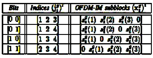
terms whose positions carry information for MIMO-OFDM-IM [1]. Selection of index is performed by reference
look up table. For N=4, K=3 are given in table I & II respectively.
Table II: N= 4, K=3 & P1=2
Different OFDM IM sub bloc s are used to form main OFDM bloc ; t = 1, 2……T. To transmit the elements from uncorrelated channels G*N bloc interleaves are used at transmitter. This interleaved frames are processed by IFFT to obtain q t , t = 1… T. ssume time domain OFDM symbols are normalized to have unit energy, and then it makes
use of different blocks such as cyclic prefix (CP), parallel to serial, digital to analog conversions. After words the
resulting signal is transmitted over frequency selective Rayleigh fading MIMO channel. After removing cyclic
prefix & performing FFT operations in each branch of the receiver, the input - output relationship of MIMO OFDM
IM scheme in frequency domain is obtained as [1]
̃ = ∑ ( ̃) ɤ=t + (1)
̃ = ,( ) ( ) ( ) ( ) ( ) ( )-T
For r = 1…R, where is the vector of the received signals for receiving antenna r, hɤ,t is the frequency response of
wireless channel between transmit T & receiver R & Wɤ is a vector of noise samples. The elements of hɤ,t and Wɤ
follow CN (0, 1) and CN (0, N O,F) distributions, respectively, where
NO,F denotes the variance of the noise samples in the frequency domain, which is related to the variance of the
noise samples in the time domain as ( ( )⁄ ) .
3.DETECTION OF MIMO-OFDM-IM SCHEME
The received signals are obtained for receive antenna r, after block deinterleaving as,
∑ ( ) ̃ ̃ (2)
Where ̃ and ̃ are deinterleaved versions of ̃ and ̃ respectively. The detection of the MIMO
OFDM-IM scheme can be performed by the separation of the received signals in (2) for each sub block g = 1…G
[1].
∑ ( ) ̃ ̃ (3)
For detection maximum likelihood (ML) detector is a straight forward but costly solution which can be realized for
̂ ̂ ⏟
∑ ∑ ( ) ̃ (4)
Due to interference between sub blocks of different transmit antennas ML has a make a joint search over all
transmit antennas, but because of complex multiplications which become impractical for higher order modulations
& MIMO systems that’s why in this wor we propose MMSE detection & LLR calculation based detector ,which
has linear decoding complexity as that of classical MIMO OFDM & MMSE. Data symbols can be simply
recovered after processing received signal vector with MMSE detector. It is not possible to detect all the
transmitted symbols for a given subcarrier therefore N successive MMSE detections are performed for proposed
scheme. Unlike classical MIMO OFDM ̂contains some zero terms, whose positions carry information therefore
independent detection of the data symbols is not a straight forward problem for proposed scheme as an example
rounding off individually the elements of ̂ to the closet constellation point may result a catastrophic active index
combination that is not included in the reference look-up table, which makes the recovery of index selecting bits
impossible [1]. In order to determine the active subcarriers in ̂ LLR detector is used. The LLR detector of OFDM
IM scheme provides the logarithm of ratio of posterior probabilities of the frequency domain symbols by
considering the fact that their values can be either non zero or zero. This ratio provides information on active status
of corresponding subcarrier index n of transmit antenna t:
( ) ∑ . ( ) ̂ ( )/
( ( ) | ̂ ( ))
(5)
4.MIMO OFDM IM USING FREQUENCY OFFSET
The sensitivity of OFDM systems to frequency offset compared with single carrier System is a major disadvantage.
In general, Frequency offset is defined as the difference between the nominal frequency and actual output
frequency. In OFDM, the uncertainty in carrier frequency, which is due to a difference in Frequencies of the local
oscillators in transmitter & receiver gives rise to a shift in frequency domain this shift is also referred to as
frequency offset.
As shown in Fig2, when the centers of adjacent subcarriers are shifted because of the frequency offset, the adjacent
subcarriers nulls are also shifted from the center of the other subcarrier. The received signal contains samples from
this shifted subcarrier, leading to ICI. It can also be caused due to the Doppler shift in the channel. The main factor
that affects the rate of fading is the mobility of the receiver relative to transmitter. As the receiver moves with some
velocity relative to the transmitter, the phase shifts of the received signal changes. This phenomenon is known as
the Doppler shift. The Doppler rate gives information about how fast the channel is varying compared to the data
rate. In general, Doppler frequency is given by: . Where θ is the angle of the signal direction
& is the maximum Doppler frequency, v is the velocity of the receiver, is the carrier
frequency and c is the propagation velocity of the transmitted signal (speed of light). In this work we propose to use
frequency offset with MIMO OFDM IM to overcome this high mobility effect.
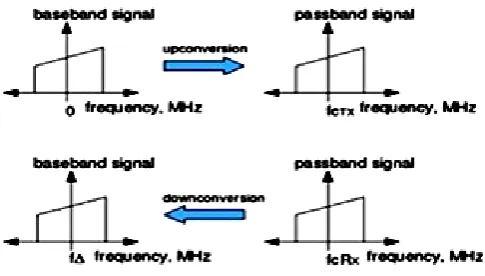
Fig 3: concept of frequency offset.
As shown in Fig3, in a typical wireless communication system, the signal to be transmitted is up converted to a
carrier frequency prior to transmission. The receiver is expected to tune to the same carrier frequency for down
converting the signal to baseband, prior to demodulation. However, due to device impairments the carrier
frequency of the receiver need not be same as the carrier frequency of the transmitter. When this happens, the
received baseband signal, instead of being centered at DC (0MHz), will be centered at a frequency F_∆, where F_∆=F_TX-F_RX. Thus the demodulation of a signal with an offset in the carrier frequency can cause large BER &
may degrade the performance of symbol synchronizer. Therefore important to estimate the frequency offset &
minimizes / eliminates its impact. If frequency offset is denoted as ∆_fC, the OFDM signal generated by the
transmitter denoted as s(t)-(6) and y(t)-(7) is the signal received by the receiver, then frequency offset is (8) given
by
( ) ( ) (6)
Then received signal has phase offset equal to
( ) ( ) ( ) (9)
The frequency response of each sub-channel should be zero at all other sub-carrier frequencies, i.e., the
sub-channels shouldn’t interfere with each other. The effect of frequency offset is a translation of these frequency
responses resulting in loss of Orthogonality between the sub-carriers and leading to ICI. These destructive effects
of the frequency offset can be corrected by estimating the frequency offset itself & applying proper correction. In
ideal case of no frequency offset, the demodulated value should be zero for whole time. When frequency offset is
present, the effect is like random noise which increases with frequency offset. As frequency offset value is
increasing, received signal is more distorted and the frequency offset values bigger than 0.6% the received data are
unreadable. Thus in this work we propose that by operating this frequency offset we can reduce the BER (Bit Error
Rate) than previous work [1] MIMO OFDM IM.
5.MATLAB RESULTS
In this work, we propose results via numerical calculations on MATLAB platform. We used BPSK (Binary Phase
Shift),QPSK (Quadrature Phase Shift Key), QAM (Quadrature Amplitude modulation) modulations & ML/MMSE
detections for three different T*R MIMO configurations: 2*2,4*4 ,8*8. The following parameters are assumed in
MATLAB i.e. NFFT=64, NDSC=52, nsym=10^4 & frequency offset range ±200KHZ. In this work we compare
the BER performance of MIMO OFDM IM & classical OFDM using frequency offset. As seen from figures (4, 5,
and 6) the proposed scheme provides significant BER performance improvement compared to classical OFDM &
still maintains its advantage over classical MIMO OFDM.
Fig4: Phase Noise Estimation MIMO OFDM IM system.
Graph plots SNR on x axis and BER on y axis. The bit error rate or bit error ratio (BER) is the number of bit errors
divided by the total number of transferred bits during a studied time interval. BER is a unit less performance
measure, often expressed as a percentage. It achieves significantly better BER (almost nearer to zero) performance
than classical MIMO OFDM. This scheme is very useful in wireless communication in order to compensate the
effect of mobility. This graph is obtained using BPSK where one binary data is sent at a time. This is the simplest
Fig 5: symbol error rate Performance.
As seen from Fig5 it achieves significantly better BER (almost nearer to zero) performance than classical MIMO
OFDM. This graph is obtained using QPSK & it is the digital modulation technique. Quadrature Phase Shift
Keying (QPSK) is a form of Phase Shift Keying in which two bits are modulated at once, selecting one of four
possible carrier phase shifts (0, Π/2, Π, and 3Π/2). QPSK perform by changing the phase of the In-phase (I) carrier
from 0° to 180° and the Quadrature-phase (Q) carrier between 90° and 270°. This is used to indicate the four states
of a 2-bit binary code. Each state of these carriers is referred to as a Symbol. In Fig6 this graph is obtained using
QAM, in that same combination of amplitude and phase can carry the concept of transmitting more bits per symbol.
Fig 6: Time and Frequency Offset Estimation
6.CONCLUSIONS AND FUTURE WORK
The proposed work called MIMO OFDM with index modulation using frequency offset as an attractive alternative
multicarrier transmission technique for 5G networks. It has been shown via numerical calculations on MATLAB
platform that proposed work provides significant BER performance improvement almost nearer to zero over
classical MIMO OFDM for several different configurations. As research on this concept has been going on in
future, we can improve its performance further especially for more complex modulation like QAM by using more
advanced detection techniques.
REFERENCES
[1] J. ndrews, S. Buzzi, W. Choi, S. Hanly, . Lozano, . Soong, and J. Zhang, “What will 5G be?,” IEEE
[2] Muthukumaran. N and Ravi. R, 'Design and analysis of VLSI based FELICS Algorithm for lossless Image
Compression', International Journal of Advanced Research in Technology, Vol. 2, No. 3, pp. 115-119,
March 2012.
[3] Manoj Kumar. B and Muthukumaran. N, 'Design of Low power high Speed CASCADED Double Tail
Comparator', International Journal of Advanced Research in Biology Engineering Science and
Technology, Vol. 2, No. 4, pp.18-22, June 2016.
[4] N. Muthukumaran, 'Analyzing Throughput of MANET with Reduced Packet Loss', Wireless Personal
Communications, Vol. 97, No. 1, pp. 565-578, November 2017, SPRINGER.
[5] P.Venkateswari, E.Jebitha Steffy, Dr. N. Muthukumaran, 'License Plate cognizance by Ocular Character
Perception', International Research Journal of Engineering and Technology, Vol. 5, No. 2, pp. 536-542,
February 2018.
[6] N. Muthukumaran, Mrs R.Sonya, Dr.Rajashekhara and Chitra V, 'Computation of Optimum ATC Using
Generator Participation Factor in Deregulated System', International Journal of Advanced Research Trends
in Engineering and Technology, Vol. 4, No. 1, pp. 8-11, January 2017.
[7] W. Li, H. Zhao, C. Zhang, L. Zhao, and R. Wang, “Generalized selecting sub-carrier modulation scheme in
OFDM system,” in IEEE Int. Conf. Commun. Wor shops, Jun. 2014, pp. 907–911.
[8] E. Başar, “OFDM with index modulation using coordinate interleaving,” IEEE Wireless Commun. Lett,
no. 99, pp. 1–4, Apr. 2015.
[9] W. ziz, 1E. hmed, G. bbas,” Performance nalysis of Carrier Frequency Offset (CFO) in OFDM using
M TL B,” Journal of Engineering (JOE) Vol. 1, No. 1, 2012.
[10] Pradeep Kumar Naya , “Inter Channel Interference in High Mobility OFDM,” International Journal of
Electrical, Electronics and Data Communication, ISSN: 2320-2084 Volume-2, Issue-1, and Jan.-2014.
[11] Ertuğrul Başar, Member, IEEE “On Multiple-Input Multiple-Output OFDM with Index Modulation for
Next Generation Wireless Networ s”, IEEE Signal Processing Letters, “UNPUBLISHED”.
[12] Muthukumaran. N and Ravi. R, 'Hardware Implementation of Architecture Techniques for Fast Efficient
loss less Image Compression System', Wireless Personal Communications, Volume. 90, No. 3, pp.
1291-1315, October 2016, SPRINGER.
[13] Muthukumaran. N and Ravi. R, 'The Performance Analysis of Fast Efficient Lossless Satellite Image
Compression and Decompression for Wavelet Based Algorithm', Wireless Personal Communications,
Volume. 81, No. 2, pp. 839-859, March 2015, SPRINGER.
[14] Muthukumaran. N and Ravi. R, 'VLSI Implementations of Compressive Image Acquisition using Block
Based Compression Algorithm', The International Arab Journal of Information Technology, vol. 12, no. 4,
pp. 333-339, July 2015.
[15] Muthukumaran. N and Ravi. R, 'Simulation Based VLSI Implementation of Fast Efficient Lossless Image
Compression System using Simplified Adjusted Binary Code & Golumb Rice Code', World Academy of
[16] E. Başar, Ü. ygölü, E. Panayırcı, and H. V. Poor, “Orthogonal frequency division multiplexes with index
modulation,” IEEE Trans. Signal Process. vol. 61, no. 22, pp. 5536–5549, Nov. 2013.
[17] Ruban Kingston. M,Muthukumaran. and N, Ravi. R, 'A Novel Scheme of CMOS VCO Design with
reduce number of Transistors using 180nm CAD Tool', International Journal of Applied Engineering